

Abstract
The high-speed dynamics of a hybrid distributed feedback semiconductor laser heterogeneously integrated onto silicon is experimentally investigated in the presence of external optical feedback. The laser fabrication relies on a proper modal engineering in which light is generated in the III–V material and stored in the low-loss silicon region in order to substantially enhance the quality factor of the cavity resonator. In this work, the hybrid laser is found to be insensitive to parasitic reflections leading to a 10 Gbps floor-free transmission with a power penalty no greater than 1.5 dB at room temperature. As a conclusion, owing to the large quality factor, a high coherence collapse level is unveiled in such laser indicating its vast potential to serve as an alternative solution for the development of isolator-free applications in future photonics integrated circuits. A qualitative interpretation is also provided by linking the standard feedback equations to the quality factor of the resonator.
Export citation and abstract BibTeX RIS

Original content from this work may be used under the terms of the Creative Commons Attribution 4.0 licence. Any further distribution of this work must maintain attribution to the author(s) and the title of the work, journal citation and DOI.
1. Introduction
Photonics integrated circuits (PIC) continue to gain a significant amount of attention from different communities, in particular from the datacom industry due to the key attributes these devices can offer to a wide range of applications to include improved performance, size reduction and enhanced power efficiency [1]. These features are critical for the next generation of data centres and essential to meet the new optical network requirements in order to handle the afresh complexity of data traffic. In addition, it is important to emphasize that the extraordinary development of PIC technologies is one of the most attractive solutions considered to address the bottlenecks associated with the ongoing digital transformation and enable the rapidly increasing bandwidth demand required by data centres to satisfy the desired hyper-connectivity levels [2, 3]. Although it is well-established that PICs gather all the essential functionalities of photonics systems, it is also known that optical isolation is a serious drawback since it remains quite difficult to position an optical isolator with both sufficient isolation ratio and low insertion loss at the output of the laser as it is commonly done in fiber and free space optics [4, 5]. Therefore, designing ultra-stable semiconductor lasers with the intent to tackle unwanted short-cavity reflections remains a critical challenge for future integrated photonic technologies. Very recently, multiple solutions to reach optical feedback insensitivity have been investigated. For instance, a new type of optical feedback insensitive integrated semiconductor ring laser was introduced with an optical isolator included in the optical cavity [6]. However, despite the observed 5 dB of isolation and 3 dB increase of tolerance for external optical feedback, the gain in terms of feedback insensitivity is quite limited due to a very complex structure where additional parasitic reflections may also occur [6]. In order to maintain a much simpler laser design, other configurations can be considered such as those based on nanolasers [7] or quantum dot (QD) material systems [8]. In the former configuration, it was shown that such nanodevices can strongly suppress the dynamic instabilities induced by external optical feedback in spite of a limited optical output power. Interestingly, owing to a unique reduction of the relaxation oscillation frequency (ROF) characteristics, a possible total suppression of the coherence collapse (CC) associated with chaotic oscillations was pointed out [7]. In the latter configuration, it was demonstrated that QD lasers with robust single-state emission, large damping and low linewidth enhancement factor are powerful candidates capable of reaching a high level of feedback insensitivity [9, 10]. In the case of epitaxial lasers on silicon, this effect can be further accelerated due to the epitaxial defects which may contribute to a reduced carrier lifetime [11, 12]. At the system level, an InAs/GaAs QD transmitter integrated on Si substrate without optical isolator was proposed for core I/O applications with a 25 Gbps floor-free transmission [13]. In addition to that, other angles being investigated are steered towards reaching feedback insensitivity by considering a semiconductor laser cavity having a resonator with a high quality (Q) factor [14]. A pioneer work was proposed in the context of narrow phase noise measurements where a high-Q passive silicon resonator has also evidenced a superior robustness against optical feedback [15]. Here, we build up on this prior effort by considering a low-noise hybrid laser which is based on the same design concept hence a high-Q factor III–V on silicon hybrid laser consisting of a harmonic optical potential well cavity. In this work, the optical feedback investigation is performed more in-depth including a 10 Gbps test bed experiment and a side by side comparison with existing technologies based on quantum wells. In [16], a photon lifetime as high as 100 ps and a relative intensity noise below 147 dB/Hz with a constant level over 20 GHz has already been reported. The experimental results presented in this letter demonstrate that a high-Q factor laser is able to tolerate disturbances caused by unintentional back-reflections generated from various sources. Our findings indicate the potential for feedback insensitivity of a single mode laser with a distributed feedback (DFB) configuration and a large Q factor. The high level of the CC regime permits a 10 Gbps error-free transmission over a 10 km fiber coil. We believe that compared to the aforementioned solutions, the one proposed in this study does not require neither a complex design [6], nor a nanocavity [7], nor epitaxial growth of QDs [8], nor the utilization of any artificial solution (e.g. external cavity) [17]. Its enhanced performance is simply the result of the laser's cavity large Q factor, which pushes the CC regime transition to much higher reflection levels as compared to their conventional III–V counterparts which is a propitious feature of paramount importance for the development of future low-cost PICs and isolator-free applications. A large Q factor stems from the reduction of the material losses because the hybrid III–V/Silicon structure allows the storage of the optical energy in the Silicon region, where losses are less predominant than in the III–V material, which in turn results in a much lower gain required to achieve lasing.
2. Device and experiment
2.1. Laser structure
Figure 1(a) sketches the cross section of the high-Q laser structure, bonding a silicon photonic layer onto a quantum well (QW) gain material. The laser was made at III-V Lab and CEA Leti. The geometry is optimized in such a way that the mode is buried into a rib silicon waveguide with a shallow grating of 30 nm deep teeth. The width of the grating is tapered longitudinally to create an effective confining potential which allows a single, bell-shaped longitudinal mode within the stop band of the DFB [14]. It has been demonstrated that this mode has a large Q factor leading to a cavity photon lifetime of ∼100 ps. The Q factor term is an alternative description of the laser's losses meaning that high-Q lasers are simply low-loss devices. In order to harness the low internal loss of the silicon resonator, the contribution to loss from the active material has to then be reduced, by decreasing the overlap between the optical field and the gain material. The modal gain is decreased as well, but it remains large enough to compensate for losses. The choice of a large silicon (Si) waveguide with width WSi = 2 μm leads to the desired overlap of about 5% as shown in figure 1(b). The mirror losses, more precisely the coupling rate of the cavity to the output is adjusted to ensure mild overcoupling, hence improving differential efficiency without increasing the threshold. The total length of the cavity consists of three sections. The first section corresponds to the parabolic tapered grating with length Lc and the other two are related to uniform sections at each side with length Lb. The total cavity length  is varied from 400 to 900 μm.
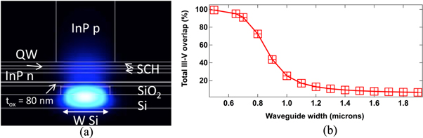
Figure 1. (a) Schematic of the high-Q DFB laser cross-section, (b) III–V total overlap versus silicon waveguide width.
Download figure:
Standard image High-resolution imageThe inset of figure 2(a) depicts the light–current (L–I) characteristics of the free-running device having a total cavity length of 900 μm. The threshold current Ith is close to 40 mA at room temperature (293 K) whereas the optical spectrum in figure 2(a) confirms the single mode behavior with a side-mode suppression ratio (SMSR) > 50 dB at 3 × Ith (114 mA) and a dominant emission wavelength of 1 562.6 nm. In this fabrication, the Q factor is maximized by increasing the device length hence allowing a stronger grating coupling coefficient at the center of the cavity (≈200 cm−1) and a large cavity photon lifetime. Figure 2(b) shows that the Q can reach up to 4 × 10⁵ when WSi is increased to 2 microns, which results in a substantial reduction of the threshold current. Let us stress that the latter saturates since increasing the cavity length also decreases the carrier density for the same injected current. Here, the Q is computed by evaluating the DFB loss and the III–V overlap with the silicon waveguide as well as with the p and n doped InP regions (figure 1(b)). The former analysis is performed with the transfer matrix method (TMM) [18] whereas the latter is done thanks to a commercial software [19].

Figure 2. (a) Optical spectrum of the high-Q DFB laser and L–I curve (inset) at 3 × Ith, (b) the calculated Q factor and threshold current as a function of the total cavity length.
Download figure:
Standard image High-resolution image2.2. Optical feedback setup
Figure 3 represents the experimental setup used to investigate the effects of optical feedback under both static and dynamic configurations. The emission from the laser diode (LD) is coupled by a lens-end fiber with anti-reflection (AR) coating. A 90/10 splitter is used to send 90% of the coupled light to the back reflector (BKR) in order to control the feedback amount, which, on this stage, is estimated ranging from 0 to about 4% of the emitting power, i.e. the maximal attainable amount of feedback is of −14 dB. In the following, the feedback strength rext defined as the ratio between the reflected power and the free-space emitting power at the front facet is normalized to the maximal level, hence ranging from 0 to 100%. The 7 m long external cavity length implies a long-delay feedback scenario, meaning that the effects associated with the phase of the back-reflected field can be neglected. The remaining 10% is amplified with an erbium-doped fiber amplifier (EDFA) and filtered by a thin band-pass filter (TBPF). A second 90/10 splitter is also used to send 10% of this light to the power meter (PM), the optical and the electrical spectrum analyzer (OSA and ESA) to monitor the coupled light via an optical switch (SWT). The remaining 90% is then modulated by a Mach–Zehnder modulator (MZM) to be analyzed by both the error detector (ED) and oscilloscope (OSC) before and after transmission through a 10 km fiber coil. A pseudo-random bit sequence (PRBS) of 31 bits bit error rate (BER) transmission stress pattern is used with 2 Vpp amplitude to estimate the BER output at 10 Gbps.

Figure 3. Experimental set-up used for optical feedback investigation.
Download figure:
Standard image High-resolution image3. Results and discussion
In what follows, the experiments are all performed at room temperature and at three times the threshold. Figure 4 illustrates the optical and electrical spectra maps of the high-Q DFB laser. Figure 4(a) unveils a steady operation of the device under a variation of optical feedback strengths. In this case, the device does not exhibit any perturbations up to rext = 100% (i.e. −14 dB), which is indicative of the enhanced tolerance high-Q lasers have against the detrimental effects of parasitic reflections. The electrical spectrum of the device is displayed in figure 4(b) where a stable operation can also be observed without any evidence of ROF often expected from a precursor regime associated with the CC operation. This last statement is in agreement with the very long photon lifetime and large damping factor already reported in [16].

Figure 4. (a) Optical and (b) electrical spectral maps of the high-Q DFB laser with respect to the optical feedback strength.
Download figure:
Standard image High-resolution imageAs a reference, figure 5(a) and (b) displays the optical and radio frequency (RF) spectral evolution of a conventional QW DFB laser. The total reflection ratio is kept at the same level as in the high-Q DFB laser to quantitatively assess the strengths and limitations exhibited by these two types of structures. As we can see, the strong periodic oscillations displayed by the QW DFB laser during the route to chaos are well pronounced: first, the laser remains stably operating in both the optical and RF domain, the red shift of the lasing mode visible in figure 5(a) is attributed to the reduction of the carrier density due to the increasing feedback; then as the feedback value reaches 1% of the total reflection, the laser is suddenly destabilized with periodic oscillations gradually raising up. It is also evident that as the feedback strength continues to raise, the lasing operation of the device becomes progressively chaotic which translates into a largely broadened lasing mode and an extended RF signal span in the optical and RF spectra.

Figure 5. (a) Optical and (b) RF spectral map of a conventional QW DFB laser, eye diagrams at (c) level (I) and (d) level (II) marked in the map.
Download figure:
Standard image High-resolution imageIt is well known that any change in the feedback phase inside the cavity have a significant impact on the overall performance of the QW DFB laser and strongly affects its operation. Under a variation of optical feedback strengths, the relaxation oscillations of a conventional QW DFB device become easily excited subsequently leading to a chaotic oscillation state of the laser's output [20]. Figures 5(c) and (d) display the eye diagrams under the back-to-back (B2B) configuration (absence of transmission across the optical fiber) for two different feedback levels: (I) where the laser is mostly stable (rext ≈ 0.3% (i.e. −40 dB)), and (II) at the beginning of destabilization (rext ≈ 3% (i.e. −30 dB)). At level (I), a clear eye diagram is obtained; as the optical feedback goes beyond level (II), the eye diagram starts to deteriorate due to CC operation which then limits the amount of data transmitted. Although the eye diagrams remains pretty open for both cases, the corresponding BER increases to approximately 10−5 at stronger feedback levels thus transmitting such signal through conventional single-mode fibers in an error-free state is no longer possible. On the other hand, we unveil a much higher tolerance offered by high-Q devices when subjected to optical feedback as shown in figure 6.

Figure 6. (a) BER characteristics of the high-Q laser with (blue and cyan triangles) and without (red and magenta squares) feedback, eye diagrams (b) in B2B without feedback and (c) with maximal feedback after transmission.
Download figure:
Standard image High-resolution image
Figure 6 depicts the BER characteristics and the eye diagram of the high-Q DFB laser for the different experimental conditions. In figure 6(a), the red squares represent the reference curve without the presence of optical feedback, and the blue triangles are obtained when the laser is subject to the maximum feedback (i.e. rext = 100%) for B2B measurements. After transmissions, floor-free results are also achieved successfully. The magenta squares represent the reference curve for the solitary conditions and the cyan triangles are obtained at the maximum feedback strength. To sum, this work validates that the high-Q factor prevents any degradation of the laser's performance under strong optical feedback conditions without any CC regime operation.
Overall, the overlapping curves for both sets of measurements demonstrate that the high-Q hybrid laser's performance is not altered by external feedback and that an error-free transmission can be achieved close to 10−12 and 10−10 BER for B2B and transmission operation respectively, implying that the power penalty of ∼1.5 dB is primarily caused by the fiber dispersion during the transmission. Figure 6(b) and (c) display the eye diagrams for the B2B solitary device and after transmission with maximum feedback. In both diagrams, the eye remains clean and well opened. The results presented herein indicate that high-Q lasers exhibit an enhanced tolerance against optical perturbations and serve as tool to potentially achieve error-free transmission at higher bit rates.
4. Physical interpretation
The improved performance and the relative optical feedback insensitivity powered by this device is due to its unique structural engineering design, which leads to a large quality factor. If ω is the laser angular frequency, the total, internal and external quality factors are:


and

with vg the group velocity, α0 the internal loss, αm the transmission loss and τp the cavity photon lifetime. From (1), (2 ), and (3), it is possible to link Q, Qi, and Qe such that

The high-Q laser mitigates the losses described above thus increasing the photon lifetime to about 100 ps [16]. It is also noted that Qe should not be above Qi to keep a reasonable external efficiency.
In addition, it is known that the external optical feedback induces an angular frequency shift whose expression is given by [21]

where φ is the phase of the feedback wave,  the roundtrip time in the external cavity, α the linewidth enhancement factor and C the coupling coefficient expressed as

with τint the photon roundtrip time within the laser's cavity, and R the power reflectivity of the output facet coupled to the external cavity. Usually, large values of C increase the number of external cavity modes giving rise to modal competition where at large feedback strengths leads to the CC regime [22]. By incorporating Qe into (6), C can be rewritten as follows

It is essential to note that this novel equation holds under the assumption that the high-Q laser has a perfect power reflectivity approaching unity hence the quality factor can directly be described as a function of the transmission loss. Despite (7) being a limiting case of (6), it gives a qualitative insight on how Qe impacts the laser's feedback sensitivity. When Qe factor is large, the C coefficient can be kept to a low value thus providing a relative feedback insensitivity regardless of the feedback strength.
On the other hand, it was shown that the onset of the CC can be determined when the frequency shift (5) is maximized or a certain critical feedback level is greater than the ROF such as  [23]. Using (5) and (7), the onset of the CC rcrit can be linked to Qe such as

Equation (8) unveils that the rcrit of a high-Q laser occurs at a high feedback level. For the laser under study, ω/2π = 200 THz, ωr/2π = 2 GHz, τp = 100 ps, and α = 2.5. Altogether, it is found Qe = ω × τp = 1.2 × 10⁵ leading to a rcrit beyond −10 dB. This last value corresponds to an upper limit case of the CC level which can not be reached in our experiments due to the loss in the fiberized setup. Despite that, the high stability achieved herein for the high-Q laser shows a high CC level beyond rext = 100% (i.e. > −14 dB), which corresponds to a strong improvement when compared to the QW DFB laser for which the CC level pops-up at rext = 3% (i.e. −30 dB).
5. Conclusions
To conclude, the dynamics of a high-Q distributed feedback semiconductor laser heterogeneously integrated onto silicon is experimentally investigated at room temperature. This unique laser design provides a prolonged photon cavity lifetime of the lasing mode due to the material absorption properties. Owing to the large quality factor, a high coherence collapse level is unveiled which transforms into a 10 Gbps floor-free transmission under the most stringent optical feedback conditions. This work brings novel findings and useful insights towards the understanding of efficient semiconductor lasers operating without optical isolator which is of great significance for the development of integrated photonics technologies. Other applications requiring improved coherence and precisely controlled light sources will also benefit from these distinctive attributes and will be considered in the future.
Acknowledgments
The authors acknowledge Doctors A Gallet and GH Duan for fruitful discussions as well people from III-V lab for providing the laser structures.