
Abstract
Low-carbon steel is a widely used structural metal that, when fractured, can be repaired with high temperature processes. There are many applications, however, that would benefit from a room-temperature repair process which maintains the steel microstructure and prevents nearby materials and electronics from overheating. This work seeks to enable effective room-temperature healing of steel by understanding how ion transport and electrolyte chemistry influence growth morphology and strength in fractured steel struts repaired with nickel electrodeposition. Experiments and simulations show that pulsed electroplating mitigates diffusion-limited growth to enable smooth and dense nickel deposits that have 4× higher adhesion to steel than nickel deposited by potentiostatic electroplating. By combining pulsed electroplating and electrolyte chemistry selection, fully fractured steel wires could be repaired to achieve up to 69% of their pristine wire strength. Finally, a simple geometric model highlights the advantageous energy and time requirements of electrochemical healing across length scales.
Export citation and abstract BibTeX RIS
1. Introduction
Biological materials and organisms, such as bone [1], mollusks [2] and many plant species [3], possess healing capabilities which allow them to repair fractures at room temperature or at low homeostatic temperatures (∼20 °C–40 °C). This low temperature healing has inspired many advances in synthetic materials, most notably room-temperature self-healing polymers which repair fractures using stored monomer polymerization, chain re-entanglement, non-covalent bonding, and reversible bonding [4, 5]. In contrast to polymers, metals have proven more difficult to heal at room temperature due to the very slow transport rates of metal atoms (10−45–10−35 m2 s−1 diffusivities, for example) [6, 7]. If realized, effective room-temperature metal healing would be advantageous for many applications, including multifunctional or composite materials where the low temperatures would prevent damage to heat-sensitive batteries, materials, or electronics. In addition, the low energy required for room-temperature metal healing makes it advantageous in energy constrained systems, such as battery-powered robots or vehicles. There are also several important aluminum and nickel alloys prone to cracking from thermal stresses [8–10] and room-temperature healing techniques could more effectively repair these materials. Despite the many applications of room temperature metal healing, slow metal transport rates have significantly restricted the techniques available to realize this functionality.
Most metal healing techniques require temperatures close to or above the melting point of the metal, so that metal atoms can diffuse or flow to the damage site. Some high temperature healing examples include impurity diffusion to heal creep fractures in precipitation-hardened alloys [11] and solid-liquid phase transformations [12]. These high temperature healing techniques require up to 109 J mm−1 of healed crack length [13] and change the microstructure. Energy expenditure can be lowered using low-melting temperature eutectic alloys [14] or by restricting high temperatures to a microscale area around the crack using localized joule heating [15, 16] or a controlled exothermic reaction [17], but these techniques still require high local temperatures.
Electrochemical healing is the only technique that has realized room-temperature healing of metals [13]. In this approach, metal atoms were transported as ions dissolved in a solvent, as opposed to their reduced metallic form, which allowed them to migrate under the influence of an electric field and increased their diffusivity by 30 orders of magnitude, from about 2 × 10−41 m2 s−1 as solid Ni atoms [18] to about 1 × 10⁻⁹ m2 s−1 as Ni2+ ions in water [19]. These ions were then selectively reduced to form metal atoms at the damage site, which fused fractured surfaces together and enabled effective, rapid, and low-energy healing of metals at room temperature [13]. Although electrochemical healing was able to fully recover the tensile strength of nickel foams using nickel ions with as little as 4 h of healing time [13], a more detailed understanding of this healing process is required to repair the wide variety of useful structural metals.
In this paper, we elucidate the impact of ion transport and electrolyte chemistry on room-temperature electrochemical healing of steel. This work focuses on low-carbon steel (also known as mild steel) because it is widely used in diverse structural applications, such as ship hulls, machinery, structural beams, and concrete-reinforcing bars [20]. Figure 1(a) shows the electrochemical healing process. A low-carbon steel wire is initially coated with a passivating polymer coating. Upon fracture, steel is exposed to the surrounding electrolyte so that nickel ions can be electrochemically reduced to solid nickel on the fractured surface (figure 1(b)). As the nickel grows, it bridges the fracture and raises the tensile strength of the wire from zero to a substantial portion of its original value (figure 1(c)). Electrodeposited nickel is a good healing material because deposited films have a high strength and there are multiple electrolyte chemistries available to tune the deposition process [21]. We use a simplified cylindrical geometry to understand how chemistry and electrochemical transport affect the growth morphology and tensile strength of fractured steel wires, which represent individual struts in a cellular material. Using experimental and computational methods, we show that pulsed plating enhances nickel density and mitigates diffusion-limited growth to realize a fourfold increase in adhesion energy at the nickel–steel interface and an over threefold increase in recovered tensile strength when compared to potentiostatic (constant voltage) plating. By healing steel using different nickel aqueous electrolytes, we demonstrate that combining pulsed plating with judicious choice of electrolyte chemistry can improve adhesion at the nickel–steel interface and recover up to 69% of the pristine steel wire tensile strength. Finally, using a geometric model of a healed steel wire, we predict the charge input and time required to heal metal wires with diameters ranging from a micrometer to a centimeter.
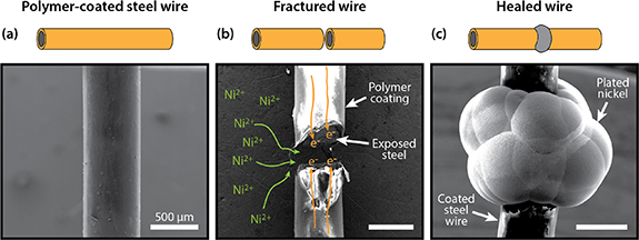
Figure 1. SEM images of (a) a pristine polymer-coated steel wire, (b) a fractured steel wire with illustrated ion and electron transport during healing, and (c) a steel wire healed after the selective electrodeposition of nickel at the fracture.
Download figure:
Standard image High-resolution image2. Materials and methods
2.1. Steel samples
Low-carbon steel wire (AISI 1006/1008), 0.58 mm in diameter, was purchased from McMaster-Carr. A Specialty Coating Systems PDS2010 conformally coated wire samples with a uniform layer of Parylene C (poly(chloro-p-xylylene)) by vapor deposition. The process started with the vaporization of the Parylene C dimer at 175 °C, which is then cleaved into monomers in a pyrolysis furnace at 690 °C. The vapor-phase monomer then flowed into the deposition chamber where it polymerized at room temperature (∼25 °C). Parylene C is an excellent passivating coating because of its chemical stability, high dielectric strength, and superior barrier properties [22]. More details on the deposition process and properties of Parylene C can be found in other publications [22–24].
2.2. Electrochemical healing
To test electrochemical healing performance, 12–14 mm long Parylene C coated steel wire samples were bisected at the midpoint with a wire cutter and inserted into a 3D-printed fixture. The fixture ensured that the fractured wire was axially aligned during the healing process, while also serving as an electrolyte vessel (figure S5 (available online at stacks.iop.org/MFM/4/024004/mmedia)). The fixture also set the spacing between steel halves (typically 250 µm), which was measured with an optical microscope. Small quantities of silicone adhesive (Sil-Poxy by Smooth-On, Inc.) applied to both ends of the wire ensured that the wire sample remained fixed, and that the crack width remained unchanged throughout the healing process. The cured silicone adhesive was mechanically removed at the end of the healing process.
We applied a few drops of isopropanol to the fracture area before the steel wire was fully immersed in a nickel aqueous electrolyte. With its low surface tension, isopropanol ensured that the electrolyte fully wetted the steel fracture surfaces. A pure nickel plate anode was immersed in the electrolyte about 1 cm away from the fracture. Both the nickel anode and steel wire were electrically connected to a BioLogic SP-300 potentiostat/galvanostat which applied a controlled potential to the steel cathode vs. Ni and measured the resulting electric current i(t). The instrument automatically stopped the healing process once a user-defined charge input Q was reached, with  . All healing experiments were conducted in a temperature-controlled lab environment, with temperature held at 20 ± 1 °C.
2.3. Electrolyte chemistry
This study used five common aqueous nickel plating electrolytes [25]. Two electrolytes, Sulfamate and Watts, were purchased from Technic Inc. as 'Elevate Ni 5910 RTU' and 'Watts Nickel Pure'. The other three electrolytes were mixed using ultrapure deionized water and chemicals purchased from Millipore Sigma. The chemical components of lab-mixed and commercial electrolytes are listed in tables 1 and 2.
Table 1. Chemical composition of lab-made aqueous nickel electrolytes.
| Components | Sulfamate strike | Modified woods | Woods |
|---|---|---|---|
| Nickel sulfamate tetrahydrate | 320 g l−1 | — | — |
| Nickel chloride hexahydrate | — | 112 g l−1 | 200 g l−1 |
| Nickel sulfate hexahydrate | — | 112 g l−1 | — |
| Nickel bromide | — | — | — |
| Hydrochloric acid | 12 ml l−1 | 50 ml l−1 | 80 ml l−1 |
| Boric acid | 30 g l−1 | 15 g l−1 | — |
| Sulfamic acid | 20 g l−1 | — | — |
Table 2. Chemical composition of commercial aqueous nickel electrolytes.
| Components | Sulfamate | Watts |
|---|---|---|
| Nickel sulfamate | 255–383 g l−1 | — |
| Nickel sulfate | — | 198–295 g l−1 |
| Nickel chloride | — | 22.5–45 g l−1 |
| Nickel bromide | 5.7–9.5 g l−1 | — |
| Boric acid | 22.5–37.5 g l−1 | 30–45 g l−1 |
| Wetting additive | 2–8 ml l−1 | — |
| Brightening additive | 15–25 ml l−1 | — |
2.4. Mechanical testing and healing performance measurements
An Instron 68SC-2 mechanical testing machine equipped with a 2 kN load cell and wedge-action grips tested the tensile properties of the healed wires. The testing speed was 5.00 mm min−1, which corresponded to a strain rate of 0.0008 s−1.
We used tensile testing data to calculate two measures of healing performance: the adhesion energy at the interface between the electrodeposited nickel and the steel surface, and the strength healing efficiency. Since the healed steel wires fractured at the nickel–steel interface, we considered that the energy released during tensile loading contributed entirely to crack propagation at this interface. Accordingly, we assumed negligible energetic contributions from elastic and plastic deformation in the steel wire or the electrodeposited nickel. As such, the adhesion energy W is expressed as:

where A is the cross-sectional area of the wire. We quantified the recovery of tensile strength σu via the strength healing efficiency eσ , which is a ratio of healed to original tensile strength:

The average tensile strength of five pristine steel wires set  (figure S6).
2.5. Characterization
To characterize the morphology of the steel wires during and after healing, we used both scanning electron microscopy (high-vacuum mode in a FEI Quanta 600 Environmental SEM) and optical microscopy (Olympus BX41 microscope equipped with a Lumenera Infinity 5 camera).
2.6. Computational model
We constructed a computational model of the wire healing using COMSOL Multiphysics software. The model geometry consisted of a two-dimensional domain with rotational symmetry around the central wire axis, as shown in figure 2. The white areas were the two halves of the fractured steel wire, 0.58 mm in diameter. The grey area was an electrolyte containing 1.46 mol l−1 nickel sulfamate (Ni(H2NSO3 −)2). The electrolyte filled a 0.25 mm gap between the fractured steel surfaces, which were designated as the cathode (red lines). The other boundaries of the steel wire (purple lines) were electrically insulating. The blue boundary on the top was the nickel anode. At the left and right electrolyte borders, we set a constant-concentration boundary condition.
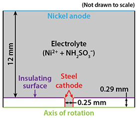
Figure 2. 2D computational model of the electrochemical healing of a steel wire as constructed in COMSOL.
Download figure:
Standard image High-resolution imageIon transport in the electrolyte, which includes contributions from both diffusion and migration, was governed by the Nernst–Planck equation [26],

where ci represents the concentration of ionic species i, Di is diffusivity, ui is mobility, φi is the electrolyte potential, F is Faraday's constant, Ni is the ionic flux, and zi is charge number. We estimate the mobility using the Nernst–Einstein equation [26],

Nickel reduction (Ni2+ (aq) + 2e− = Ni(s)) occurred at the cathode (fractured steel wire), while the opposite reaction (nickel oxidation) occurred at the anode. The reaction rates were governed by the Butler–Volmer equation [26],

where i0 is the exchange current density, αc and αa are the apparent transfer coefficients at the cathode and anode, R is the ideal gas constant, T is the operating temperature, F is Faraday's constant, and η is the overpotential.
The deformed geometry interface, a built-in COMSOL feature, used the reaction rate, as inferred from Butler–Volmer kinetics, to control the movement of the mesh at the cathode surface, thus simulating the growth of nickel. More details on the computational model and the values of the various parameters used can be found in the supplementary information.
3. Results and discussion
3.1. Effect of ion transport on electrochemical healing
To investigate the effect of ion transport on the healing of steel, we observed, by ex-situ optical microscopy, the evolution of nickel morphology on steel wires during two types of applied plating. Figure 3(a) shows microscope images of a wire healed by potentiostatic plating (top) and a wire healed by pulsed plating (bottom) after 0, 1, 2, 6, and 10 mAh of plating. During potentiostatic healing, a constant voltage (−1.5 V vs. Ni) was applied to the fractured wire throughout the healing process. During pulsed plating, the applied voltage alternated periodically between −1.5 V for 5 s and 0 V for 3 s. At the beginning of the healing process (0 mAh), the two freshly cut wires were fixed so that the crack widths were approximately 250 µm. After 1 mAh of charge input, potentiostatic plating resulted in rough nickel deposits with non-uniform thickness, whereas pulsed plating resulted in smooth nickel which grew uniformly across the steel surface. The images taken after 2 and 6 mAh of charge input, show that, during potentiostatic plating, the two nickel masses growing from the opposing steel surfaces first coalesced at the edges which led to a void at the center. During pulsed plating, the two nickel masses grew uniformly and coalesced first at the center, then progressively coalesced towards the edges. After 10 mAh of charge input, nickel grew into a quasi-spherical shape which connected the two broken halves of each wire. The nickel resulting from pulsed plating showed a smoother surface than the nickel resulting from potentiostatic plating.
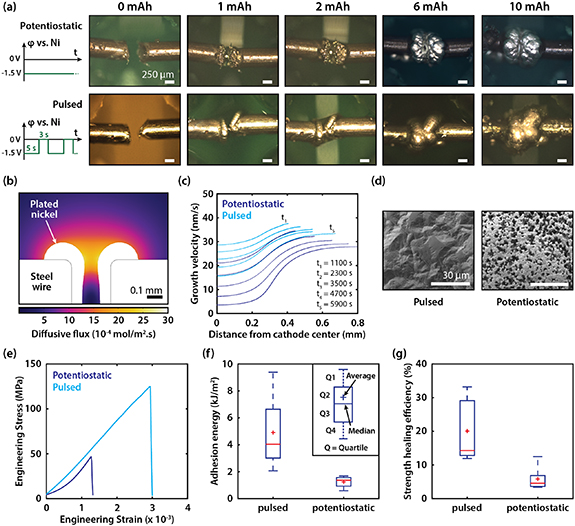
Figure 3. (a) Ex-situ optical microscopy images of nickel growth at various levels of charge input during healing by potentiostatic and pulsed plating. (b) Diffusive flux magnitude of Ni2+ ions in the electrolyte after 1 h of healing by potentiostatic plating (from computational model). (c) Growth velocity (in nanometers per second) of nickel along the cathode boundary during healing by potentiostatic plating and pulsed plating at times ranging from t = 1100 s to t = 5900 s (from computational model). At all times, the applied voltage was −1.5 V vs. Ni in the pulsed plating model. (d) SEM images of nickel surfaces after 0.5 mAh of charge input during potentiostatic and pulsed plating. (e) Stress–strain data of two steel wires healed by pulsed and potentiostatic plating. (f) Adhesion energy of steel wires healed by pulsed and potentiostatic plating. (g) Strength healing efficiency of steel wires healed by pulsed and potentiostatic plating.
Download figure:
Standard image High-resolution imageOur optical microscopy observations of the healing process showed that the type of plating had a significant influence on nickel growth morphology. We further examined nickel growth by simulating ionic transport and nickel plating during the healing of a steel wire (see section 2.6). Figure 3(b) shows the magnitude of the diffusive flux of Ni2+ ions around the fracture during healing by potentiostatic plating. The diffusive flux was about two orders of magnitude lower at the center of the fracture than at the edges. Thus, the growth of nickel is expected to be faster at the edges than at the center. Figure 3(c) shows a plot of the growth velocity of the nickel layer with respect to position along the (expanding) cathode boundary. In the case of potentiostatic plating (dark blue curves), the growth velocity varied significantly between a point at the edge and a point at the center. At t = 1100 s, the difference in growth velocity between a point at the center and another at the edge was 13.4 nm s−1. This difference increased to 24.3 nm s−1 at t = 5900 s. Meanwhile, pulsed plating resulted in a reduced variation in growth velocity. The difference between the center and the edge was 8.9 nm s−1 at t = 1100 s, and 17.7 nm s−1 at t = 5900 s. The computational model, thus, shows that pulsed plating reduced the variation in nickel growth rate along the steel surface compared to potentiostatic plating, though it did not achieve perfectly uniform growth.
The difference in growth morphology also affected the porosity of the nickel deposit and the adhesion at the nickel–steel interface. We use scanning electron microscopy (SEM) to examine the porosity of deposited nickel from both types of plating after 0.5 mAh of electrodeposition (figure 3(d)). Nickel deposited by potentiostatic plating showed significantly higher porosity than the nickel deposited by pulsed plating. This is consistent with prior nickel plating reports [27]. The lower porosity (or higher density) of nickel grown by pulsed plating enhances its strength and fracture toughness as the a crack at the interface requires more energy to propagate through the dense interface than the porous interface with a higher number of microscale pores or flaws [21].
Superior nickel–steel adhesion due to pulsed plating was confirmed by tensile testing after healing. Figure 3(e) shows stress–strain data of the best performing steel wires healed by pulsed and potentiostatic plating respectively. In both cases, the healed steel wire fractured at the Ni–steel interface, and the steel wire healed with pulsed plating exhibited higher tensile strength (maximum stress) and higher toughness. Figures 3(f) and (g) show calculated adhesion energy at the Ni-steel interface and strength healing efficiency for steel wires healed by pulsed plating and potentiostatic plating. Pulsed plating enabled a 4.1× increase in average adhesion energy (4.9 kJ m−2) compared to potentiostatic plating (1.2 kJ m−1), which was confirmed by the improved density of nickel deposited by pulsed plating (figure 3(d)). Pulsed plating also led to a 3.4× increase in average strength healing efficiency (20.0%) compared to potentiostatic plating (5.8%).
The spatial difference in nickel growth rate between the two plating methods can be explained by contrasting the rate of depletion of nickel ions at the cathode surface to their rate of diffusion. During potentiostatic plating, the nickel ion depletion rate at the center of the fracture was faster than the rate at which these ions could diffuse due to the longer diffusion length at the center compared to the edges. Consequently, the nickel growth rate at the center of the fracture was limited by diffusion. In the case of pulsed plating, periodically setting the voltage to zero after each negative voltage pulse allowed nickel ions time to diffuse to the center of the fracture so that the nickel growth was denser and more uniform across the steel surface.
From a morphological standpoint, pulsed plating significantly diminished (or even eliminated) void formation compared to potentiostatic plating, which reduced stress concentrations that lead to fracture. This observation agrees with prior work on nickel sheets healed with nickel electrodeposition, where voids impeded the full recovery of tensile strength [28]. The strength recovery after healing was inversely correlated with the metal thickness [28], which we suspect was due to larger voids forming in thicker samples with larger diffusion distances. Pulsed plating, thus, has the potential to improve the tensile strength recovery of healed metal parts of various sizes and geometries.
3.2. Effect of electrolyte chemistry on electrochemical healing
In addition to ion transport, electrolyte chemistry plays an important role in recovering the tensile strength of healed steel samples by affecting the mechanical properties of the deposited nickel and adhesion at the Ni–steel interface. To understand the role of electrolyte chemistry in electrochemical healing, we healed steel wires using five different aqueous nickel electrolytes: Sulfamate, Watts, Sulfamate Strike, Modified Woods, and Woods (see tables 1 and 2 for chemical composition).
Figure 4(a) shows the cathodic efficiency and area-normalized growth rate that are characteristic of each electrolyte at a potential of −1.5 V vs. Ni. The cathodic efficiency  is a ratio of the experimental mass of electrodeposited nickel to the theoretical mass of electrodeposited nickel determined by Faraday's law,


Figure 4. (a) Cathodic efficiency and normalized growth rate of five different nickel electrolytes at a potential of −1.5 V vs. Ni. (b) Adhesion energy at the Ni–steel interface in steel wires healed by seven different electrochemical processes. (c) Strength healing efficiency of steel wires healed by seven different electrochemical processes. (d, e) SEM images of a steel wire healed with process 6 (One-step Woods + Sulfamate) after post-healing fracture at the Ni–steel interface. The large images are details of the images in the insets (inset scale bars = 500 µm). (f) Energy dispersive x-ray spectroscopy (EDS) spectrum of fracture surface in steel wire healed with process 1 after post-healing fracture at the Ni–steel interface. (g) SEM image of the electrodeposited nickel in a steel wire healed with process 1 (Modified Woods) after post-healing fracture at the Ni–Ni interface. (h) SEM image of the fracture face in a steel wire healed with process 5 (Sulfamate) after post-healing fracture at the Ni–steel interface. The blue, green, and orange circles indicate areas characterized by three different fracture mechanisms. (i) SEM image of a non-metallic inclusion (bright area) within the nickel layer in a steel wire healed with process 7 (two-step Woods + Sulfamate) after post-healing fracture at the Ni–steel interface. (j) SEM image of non-metallic inclusions (bright area) on the steel surface in a steel wire healed with process 5 (Sulfamate) after post-healing fracture at the Ni–steel interface.
Download figure:
Standard image High-resolution imagewhere Q is the charge input (in coulombs), M is the molar mass of nickel (58.69 g mol−1), and F is Faraday's constant (96485 C mol−1). Thus,  indicates that all the electric current is used to reduce nickel ions, while
  occurs when side reactions, such as hydrogen evolution, consume a fraction of the current.
We observed a positive correlation between the cathodic efficiency and the pH of the electrolyte. We measured the lowest cathodic efficiency in the Woods electrolyte (pH = −0.2) at  . The cathodic efficiency was higher for Sulfamate Strike (pH = 1.0) and Modified Woods (pH = 0.2) at
  and
and  . With pH approaching 4, near-ideal cathodic efficiency values were realized, with
  and
and  for Watts (pH = 3.8) and Sulfamate (pH = 3.5).
The growth rate of nickel, which was normalized by the steel cathode area, did not appear to correlate with pH. The growth rate was highest for Watts (4.85 g m−2 s), Sulfamate Strike (5.81 g m−2 s), and Modified Woods (5.50 g m−2 s). Meanwhile, the Sulfamate electrolyte exhibited a low nickel growth rate (0.775 g m−2 s), in contrast with its high cathodic efficiency.
We used seven electrochemical processes based on these five nickel electrolytes to heal steel wires, as outlined in table 3. Two-step processes (3 and 6) were designed to enhance adhesion at the Ni–steel interface by using the Woods electrolyte. With its low pH and high chloride concentration, the Woods electrolyte removed native oxides and impurities and plated a thin layer of highly adherent nickel. These two processes were improved in the three-step process 7 which started with an anodic step that electrochemically etched the oxidized steel surface, followed by pulsed plating of a thin layer of nickel in Woods. The use of pulsed plating was based on our study of ion transport, which showed that it led to higher adhesion at the Ni–steel interface compared to potentiostatic plating (figure 3(f)). For all processes, we adjusted the charge input based on the cathodic efficiency of each electrolyte to ensure that the mass of plated nickel was about 11 mg regardless of the electrolyte used during healing. Therefore, 10 mAh was needed when healing with Sulfamate ( ), but 30 mAh of charge input was needed when healing with Modified Woods (
 ).
).
Table 3. Electrochemical processes used for healing steel wires.
| Process | Step | Electrolyte | Potential vs. Ni | Charge input or time | Pulsed or potentiostatic |
|---|---|---|---|---|---|
| 1 | — | Modified woods | −1.5 V | 30 mAh | Pulsed |
| 2 | — | Sulfamate strike | −1.5 V | 20 mAh | Pulsed |
| 3 | 1 | Woods | −3 V | 2 min | Potentiostatic |
| 2 | Sulfamate strike | −1.5 V | 20 mAh | Pulsed | |
| 4 | — | Watts | −1.5 V | 10 mAh | Pulsed |
| 5 | — | Sulfamate | −1.5 V | 10 mAh | Pulsed |
| 6 | 1 | Woods | −3 V | 2 min | Potentiostatic |
| 2 | Sulfamate | −1.5 V | 10 mAh | Pulsed | |
| 7 | 1 | Woods | +3 V | 0.5 min | Potentiostatic |
| 2 | Woods | −1.5 V | 2 mAh | Pulsed | |
| 3 | Sulfamate | −1.5 V | 10 mAh | Pulsed |
Since the healed wires fractured at the Ni–steel interface during tensile testing, the recovery of tensile strength after healing was limited by adhesion at the Ni–steel interface. Figure 4(b) shows the adhesion energy at the Ni–steel interface for steel wires healed with the studied electrochemical processes. Adhesion energy was below 10 kJ m−2 for processes 2–5. By combining Woods and Sulfamate electrolytes in processes 6 and 7, adhesion energy was increased substantially to 33.4 and 35.9 kJ m−2 on average. Process 7 enabled a high adhesion energy of 48.8 kJ m−2. The highest adhesion energy, 52.0 kJ m−2, was achieved using process 1 (Modified Woods); however, this data is only from two measurements since the majority of samples fractured at the Ni–Ni interface.
Figure 4(c) shows the strength healing efficiency achieved with each electrochemical process. Processes 2–4 enabled limited recovery of strength (below 20%). Process 5 (Sulfamate) improved the strength healing efficiency to an average of 20%, and up to a maximum of 33.2%. Processes 6 and 7 did not lead to a significant improvement in the average strength healing efficiency, but significantly increased the maximum achievable strength healing efficiency to 56.8% and 68.9%. Healing with process 1 presented unique challenges as most healed wires fractured at the Ni–Ni interface before tensile testing.
Scanning electron microscopy (SEM) allowed us to glean morphological cues into the fracture mechanisms of healed steel wires. Figures 4(d) and (e) show each fracture face of a steel wire healed with process 6 after it fractured at the Ni–steel interface. Figure 4(d) shows the steel side of the fracture, while figure 4(e) shows the nickel side. The fracture surfaces were smooth on both faces with no evidence of plastic deformation. EDS revealed the presence of nickel on the steel side, which may be explained by the presence of a strongly bonded thin layer of nickel on the steel surface (figure 4(f)). We hypothesize that the first layer of nickel deposited by the Woods electrolyte has a higher adhesion energy to the steel surface, compared to its adhesion energy with the nickel deposited by the Sulfamate electrolyte. Thus, fracture which appeared to occur at the Ni–steel interface from a macroscopic point of view, occurred, seemingly, at the interface between the nickel deposited by Woods and the nickel deposited by Sulfamate. A similar fracture behavior was observed in steel wires healed by process 7.
High adhesion energy at the Ni–steel interface was also achieved using process 1, yet it did not result in high strength healing efficiency due to premature fracture at the Ni–Ni interface. Figure 4(g) shows the surface of nickel electrodeposited on one half of a steel wire healed by process 1. The electrodeposited nickel exhibits severe pitting which is commonly attributed to corrosion [29]. Corrosion is likely driven by both the low pH (∼0.2) and the high chloride concentration (∼1 mol l−1) in the Modified Woods electrolyte. As the two nickel masses grew and drew closer together, it became more difficult for nickel ions to diffuse into the shrinking gap at a sufficiently high rate. The rate of corrosion, thus, exceeded the rate of diffusion, which effectively stalled the growth of nickel and prevented the two nickel masses from coalescing into a single continuous mass. Therefore, the Ni–Ni interface remained weak and prone to fracture. Interestingly, the low pH and high chloride concentration which prevented coalescence at the Ni–Ni interface, significantly improved adhesion at the Ni–steel interface by removing the native oxide and enhancing the density of active nucleation sites.
Aside from process 1, the electrochemical processes explored here resulted in healed wires that fractured at the Ni–steel interface. Figure 5(h) shows an SEM image the fracture face of a steel wire healed by process 5. This SEM image elucidates how a crack evolves as it grows through the Ni–steel interface. The orange circle encloses an area of stable crack growth characterized by a smooth surface with remnants of the delaminated nickel that remained attached. The green circle encloses a significant mass of nickel that remained on the steel surface. The crack, thus, grew out of the interface and into the nickel, resulting in brittle fracture within the nickel. Crack growth outside the interface may have been facilitated by the presence of a defect or inclusion. The blue circle highlights a void nucleation pattern which is indicative of plastic deformation. As the crack exits the interface and continues to grow into the bulk of the nickel (or steel) plastic deformation may become the dominant fracture mechanism. However, in all the healed steel wires observed under SEM after fracture, areas characterized by plastic deformation were limited, and the fracture mechanisms highlighted by the orange and green circles were more prevalent.

Figure 5. (a) Diagram explaining the two-parameter geometric model of metal wire healing. (b) Estimated charge input (in milli-ampere-hours) required to heal wires of different diameters at four different crack widths. (c) Estimated time (in hours) required to heal wires of different diameters at four different crack widths.
Download figure:
Standard image High-resolution image
Figures 4(i) and (j) are SEM images of non-metallic inclusions observed in healed steel wires after fracture. These inclusions glow brightly because they cannot conduct impinging electrons in the SEM. They are likely recrystallized nickel salts that were trapped within the growing nickel (figure 4(i)) or at the Ni–steel interface (figure 4(j)) during healing. Their presence may be responsible for weakening the electrodeposited nickel near the steel surface resulting in the low tensile strength of some healed steel wires. This agrees with prior work, where a defective near-substrate layer was proposed as a possible failure mechanism in a study of the adhesion of electrodeposited nickel to steel [30].
3.3. Predicting required healing time and charge input
While we used submillimeter-sized wires (0.58 mm in diameter) in this work, electrochemical healing can be applied to steel wires (and wires of various metals and conductive materials) with characteristic dimensions from the microscale to the macroscale. To understand if electrochemical healing could be practically used at different length scales, we conceived a geometric model based on two parameters: wire diameter d and crack width w. This model enabled first-order approximations of the charge input and time required to heal cylindrical metal wires with diameters spanning three orders of magnitude.
As shown in figure 5(a), we considered, based on empirical observations, that the volume of nickel deposited to heal a wire could be approximated by a sphere. The nickel volume was represented by the grey region of the sphere, with the spherical caps (light blue regions) and cylinders (dark blue regions) excluded. We approximated the radius of the sphere as  , the height of the spherical caps as
  , and the length of the cylinders as
  . The estimated volume of deposited nickel (grey region) was therefore

To relate the nickel volume V to the required charge input Q, we used Faraday's law,  , where is the cathodic efficiency, z is the number of electrons participating in the electrochemical reduction (here
  ), n is the number of moles of nickel, and F is Faraday's constant. Faraday's law was modified such that
  where ρ is the density of nickel (8900 kg m−3) and M is its molar mass (58.69 g mol−1). Using equation (7) to substitute the volume, V, yielded an expression for the estimated charge input,

The time required for healing Δt was estimated by relying on the area-normalized growth rate  where
where  is the area of the crack faces in a fractured wire. By manipulating Faraday's law, we obtained

The results derived from this model, which are shown in figures 5(b) and (c), assume that the Sulfamate electrolyte is used during healing. Hence,  and
and  . The results can be modified for a different electrolyte using the data in figure 4(a). For
  and
and  , which are the parameters used in our healing experiments, the model predicts that
  and
and  (figure S11). These predictions align closely with our experimental observations which supports the accuracy of this geometric model
.
(figure S11). These predictions align closely with our experimental observations which supports the accuracy of this geometric model
.
Figure 4(b) shows the estimated charge input needed to heal wires ranging in diameter from 0.01 to 10 mm at four crack widths: 0.01, 0.1, 1, and 10 mm. At a crack width of 10 mm, charge input needed to heal a wire remains around 5 × 10³ mAh regardless of diameter. For the lowest crack width (0.01 mm), charge input increases from 5 × 10⁻⁴ mAh for a 0.01 mm wire to about 6 mAh for a 10 mm wire. For reference, a high-capacity smartphone battery can provide 5000 mAh of charge input when fully charged [31]. Thus, about 800 10 mm wires (comparable in size to concrete-reinforcing bars) can be healed with the full charge of a single smartphone battery if the crack width is minimized (w = 0.01 mm). About 80 10 mm wires can be healed with a single smartphone battery if the crack width is increased to 0.1 mm. However, with a large crack width of 10 mm, more than 100 fully charged smartphone batteries would be needed to heal a single 10 mm wire. These results, thus, emphasize the importance of minimizing crack width for low-energy electrochemical healing,
Figure 4(c) shows the estimated time needed to heal wires ranging in diameter from 0.01 to 10 mm at four crack widths: 0.01, 0.1, 1, and 10 mm. At a crack width of 0.01 mm, healing requires between 1.3 h for a 0.01 mm wire and 1 min for a 10 mm wire. For a crack width of 10 mm, the times necessary for healing become impractical, ranging from about 1.3 × 10⁹ h (148 000 years) for a 0.01 mm wire to about 1400 h (58 d) for a 10 mm wire. These estimates, thus, show that it is important to minimize crack width to achieve healing within practical timeframes. Electrochemistry as a healing technique for metal wires can enable healing within about one hour regardless of wire diameter if crack width is at or below 0.01 mm.
4. Conclusion
To enable effective electrochemical healing of low-carbon steel, we sought to improve our understanding of the influence of ion transport and electrolyte chemistry on the growth of electrodeposited nickel. Using experimental and computational methods, we showed that, compared to potentiostatic plating, pulsed plating enhanced nickel density and mitigated diffusion-limited growth, thus resulting in a fourfold increase in adhesion energy at the nickel–steel interface and an over threefold increase in recovered tensile strength. By healing steel using different nickel aqueous electrolytes, we demonstrated that etching the steel surface and growing a thin layer of nickel in the Woods electrolyte, followed by healing with pulsed plating in the Sulfamate electrolyte resulted in strong adhesion at the nickel–steel interface, and enabled the strength of a healed steel wire to reach up to 69% of the strength of a pristine wire. Preventing inclusions at or near the Ni–steel interface could enable even higher values of strength healing efficiency.
Based on a simple geometric model of a healed steel wire, we showed that minimizing crack width is important to enable rapid and low-energy healing. With a crack width of 0.01 mm, over 800 10-mm steel reinforcing bars (commonly used in construction) could be healed in under one minute using only one fully charged smartphone battery (5000 mAh).
This work is the first demonstration of electrochemical healing of a metal other than nickel [13, 28], and opens the possibility of healing a variety of structural metals using selective electrodeposition. With its low energy and time requirements, as well as its effective recovery of strength, electrochemical healing can be used to minimize weight in aerospace structures, extend the service life of structural parts, and more efficiently employ scarce resources in energy-constrained systems or remote environments.
Acknowledgments
We are grateful to Dr Xuijun Yue, Dr Yue Gao, and Professor Jordan Raney for their helpful comments. 3D printed parts were made at the University of Pennsylvania courtesy of the Biomedical Library and the Additive Manufacturing Lab (AddLab) at the School of Engineering and Applied Science. We thank Peter Bruno for assistance with 3D printing. Access to a mechanical testing instrument (MTS Criterion Model 43), which was used for some preliminary tensile testing, was graciously provided by Gnana Saurya Vankayalapati and Professor Kevin Turner. This work was performed in part at the Singh Center for Nanotechnology, a node in the National Nanotechnology Coordinated Infrastructure (NNCI) network, which is supported by the National Science Foundation under grant NNCI-1542153.
Data availability statement
The data that support the findings of this study are available upon reasonable request from the authors.
Conflicts of interest
J H P and Z H are inventors on a pending patent application which encompasses at least part of the work discussed in this article.