
Abstract
The development of the DNA origami technique has revolutionized the field of DNA nanotechnology as it allows to create virtually any arbitrarily shaped nanostructure out of DNA on a 10–100 nm length scale by a rather robust self-assembly process. Additionally, DNA origami nanostructures can be modified with chemical entities with nanometer precision, which allows to tune precisely their properties, their mutual interactions and interactions with their environment. The flexibility and modularity of DNA origami allows also for the creation of dynamic nanostructures, which opens up a plethora of possible functions and applications. Here we review the fundamental properties of DNA origami nanostructures, the wide range of functions that arise from these properties and finally present possible applications of DNA origami based multifunctional materials.
Export citation and abstract BibTeX RIS

Original content from this work may be used under the terms of the Creative Commons Attribution 4.0 license. Any further distribution of this work must maintain attribution to the author(s) and the title of the work, journal citation and DOI.
1. Introduction
During the last 60–70 years, nanotechnology has been one of the driving forces of developments, which allowed for breakthroughs in different fields such as medical diagnostics, electronics, food industry and pharmaceutical industry. DNA nanotechnology is a rather young sub-field of nanotechnology, which has recently shown great potential to develop from proof-of-principle concepts into true applications. The nucleotide sequence of DNA provides the basic possibility to create programmable self-assembled materials, and the chemical stability of DNA and the possibility to synthesize specific DNA sequences by solid-phase synthesis allows for the versatile and scalable creation of DNA based nanostructures. Additionally, DNA can be easily functionalized using standard DNA chemistry [1]. The field of structural DNA nanotechnology was initiated by Ned Seeman in the early 1980s who—being a crystallographer—conceived the idea to use a crystalline DNA matrix to assemble (membrane) proteins into crystalline 3D lattices [2]. In his early works Ned Seeman used multiple artificial DNA strands to create star-like structures and tiles (such as a double crossover tile, DX) and a DNA cube with edge lengths of 7 nm [3], which are all inspired by the Holliday junction motif [4]. Initially, the field of DNA nanotechnology developed rather slowly due to challenges in the synthesis of DNA nanostructures, i.e. the necessity of a careful sequence design to avoid unwanted secondary structures and multimers, and even still extensive purification steps were necessary and the synthesis resulted in low yields. These challenges are also reflected in the fact that it took Ned Seeman about 27 years to create the first macroscopic DNA crystal, which was based on tensegrity triangles [5]. However, by the mid-2000s, the field of structural DNA nanotechnology had gained significant traction and structures such as triple-crossover tiles (TX) [6] were introduced.
The field was significantly further boosted by the introduction of the DNA origami technique by Rothemund [7]. Instead of using a few DNA strands of similar length (e.g. six DNA strands with 80 nucleotides to create the DNA cube [3]) Paul Rothemund used a long circular DNA strand (M13mp18 with 7249 nucleotides, extracted from the bacteriophage M13) as a scaffold strand, which was folded into basically arbitrary 2D shapes using a set of about 200 short artificial DNA strands serving as staple strands. In a typical design workflow an arbitrary 2D shape is first translated into cylinders corresponding to the dimensions of dsDNA, i.e. with a diameter of 2 nm. The single stranded scaffold DNA is then routed along the cylinders, and the complementary DNA is cut into approximately 200 shorter strands being 15–60 nucleotides long. These staple strands are designed in a way that they hybridize to typically three different sections of the scaffold strand, i.e. they interconnect the scaffold strand through staple crossovers (see inset of figure 1). In single-layered 2D DNA origami the distance between adjacent crossovers is typically 16 nucleotides, corresponding to 1.5 helical turns [7]. DNA origami nanostructures self-assemble from a mixture of the scaffold strand and an excess of staple strands during a thermal annealing process, and 2D structures are formed with a very high yield close to 100%. This approach is very robust since excess of staples ensures that each scaffold position will be filled meaning most of the folding errors are corrected during the annealing process.

Figure 1. Scheme of DNA origami, from top to bottom: the scaffold strand (typically M13mp18) is mixed with different sets of staple strand to form different 2D, 3D or wireframe DNA origamis. The staples (orange, blue and red) and the scaffold (green) are held together via the base pairing (the orange inset in the middle). Further, these DNA origami can be modified to include combinatory elements like sticky-ends (Rothemund triangle, red, blue and violet extensions) or freely available blunt-ends (V-shaped 3D Origami, red and orange helices) to attach DNA origamis to each other to form large-scale hierarchical structures. The scale bars in the wireframe and gear images are 50 nm and 300 nm, respectively. Insets adapted with permissions from [8, 9]. Copyright 2017 and 2015, Springer Nature.
Download figure:
Standard image High-resolution imageThe specific set of staple strands determines the shape of the DNA origami structure, and 2D DNA origami have a typical dimension of 100 nm (e.g. the Rothemund triangle has an edge length of about 127 nm, see figure 1). The DNA origami technique allows also for the folding of DNA into 3D structures by adjusting the distance between the crossovers and connecting adjacent helices in all Cartesian coordinates [10, 11]. In flat 2D DNA origami, the crossovers are placed at multiples of 16 nucleotides resulting in parallel DNA double helices arranged within a plane. By deviating from this number, the double helices can be arranged into 3D multi-layered structures. When using a crossover distance of only 7 nucleotides, the staple strand enters and exits a double helix in an angle of 240° (instead of 180° in the planar structures) [11]. This results in a hexagonal (honey comb) lattice, in which one double helix is connected to three other helices with an angle of 120° between the outer helices. A square lattice can be achieved by choosing 8 nucleotides as crossover distance creating an angle of 270° between the entering and exiting position of a staple strand [10]. In this case each double helix is connected to four double helices at an angle of 90° between the neighbouring helices. By placing the crossovers at appropriate positions and adding or omitting nucleobases in specific sections, deviations from the natural B form DNA structure and a global curvature can be achieved leading to 3D curved DNA nanostructures [12, 13] with well-defined angles and radii. The hexagonal or square 3D structures are more compact than the 2D structures and have edge lengths typically below 50 nm. Less compact and more flexible wireframe DNA origami structures can be created using multiarm junctions [9, 14]. They have the advantage that they are more stable than the dense multi-layered DNA origami structures at low ionic strength, e.g. under physiological conditions.
The initial fascination of DNA origami is based on the possibility to create arbitrary shapes on the nanoscale. However, these nanostructures are simple static structures, but a huge potential for applications of DNA origami in a wide range of scientific fields arises from the fact that each staple strand is unique, has a specific position within the DNA origami structure and can be chemically modified with functional groups (e.g. carboxy and amino groups, thiols, biotin, etc) that allow for the functionalization with other entities such as fluorescent dyes, quantum dots or nanoparticles [15]. Additionally, the staple strands can be simply extended to include non-DNA origami specific DNA sequences, to enable hybridization with other DNA strands or provide sticky ends to join individual DNA origami structures (see figure 1), which has lead into a strong effort to create larger, microscale structures made up of individual DNA origami building blocks [8, 16]. In this way functional units can be placed with a precision of a few nm providing numerous possibilities to create multifunctional materials. Additionally, by introduction of flexible elements into a DNA origami nanostructure a static structure can be turned into a dynamic structure, which could be controlled for example by physical stimuli (such as temperature) or chemical stimuli (such as pH or ionic strength). Through the introduction of site-specific chemical functionalizations as described above countless possibilities are provided to further control the DNA origami structures by other stimuli such as light (e.g. through the introduction of dyes, plasmonic nanoparticles or photoswitches) and biological stimuli such as enzymes or biomarkers that are recognized by a specific receptor, etc.
Both aspects, the possibility to precisely tune intermolecular interactions and to place chemical functionalizations, enable to interface DNA origami with the macroscale, i.e. to read-out the effect of physical, chemical and biological stimuli by microscopic, spectroscopic or electronic techniques or simply to modify surfaces in order to serve as interfaces to fine-tune specific properties of materials (see figure 2). To create such multifunctional materials from DNA using the DNA origami technique, it is essential to evaluate and improve the stability of DNA origami structures in different chemical environments, and to further minimize the costs of its fabrication. All of these aspects have seen a significant progress in recent years, which will be discussed as well in detail in this review. Finally, it should be noted that there are other techniques to create DNA nanostructures, such as the aforementioned DX and TX tiles, which are not covered here.

Figure 2. Scheme illustrating the potential of DNA origami to be applied as multifunctional materials. DNA origami in its simplest form is a static nanoscale structure. Through its programmability the non-covalent interactions in-between DNA origamis or DNA origamis and other surfaces/molecules can be precisely tuned, and additionally site-specific chemical functionalizations can be introduced. These key-properties allow for the formation of hierarchically ordered microscale structures, dynamic structures, for the interfacing with the macroscale outside world, and for the addressability by physical (e.g. temperature, light), chemical (e.g. pH, ionic strength), and biological (e.g. enzymes, ligands) stimuli.
Download figure:
Standard image High-resolution imageThis review is organized as follows. At first we will discuss the properties of DNA origami (see figure 3): the specific 2D/3D shape, the possibility to precisely tune intermolecular interactions allowing for the creation of sophisticated hierarchically ordered structures and also enabling the structuring and modification of surfaces with DNA origami in section 2. In section 3, we will discuss the functions that arise from these properties, i.e. carrying or transporting cargo, optical interfacing, patterning, lock-and-key recognition, and actuation and reversible switching. Selected examples of applications will be presented in all subsections. Then we will discuss the stability of DNA origami structures in different environments and possible strategies to improve their stability in specific settings, and to upscale the synthesis of DNA origami in section 4. Finally, section 5 will present computational tools that are used to design DNA origami structures and to assess their basic structures and properties.
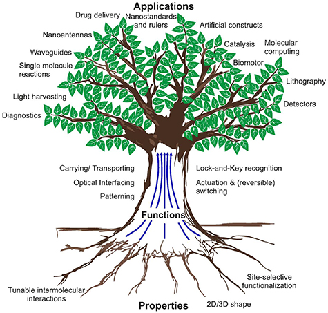
Figure 3. Overview of properties, functions and applications of DNA origami.
Download figure:
Standard image High-resolution image2. Properties of DNA origami
2.1. 2D/3D shape
For structural DNA nanotechnology, the ability to form any arbitrary, user-defined shape is a quite pivotal property of DNA origami. Although DNA origamis such as the Rothemund triangle and the 6-helix bundle (6HB) can be universally applied in several fields e.g. transportation of molecules, actuation and patterning, many applications require a specific shape to execute its intended function, such as operating as artificial constructs to mimic naturally occurring organelles or systems. The design of the shape of the DNA origami also influences factors like the global stiffness, the twisting or grooving of the DNA origami and the available sites for chemical modifications or sticky-ends. To demonstrate the importance of the shape, we are introducing here few examples how the different designs, i.e. different set of staple strands can be utilized to make static structures for vastly different applications.
First category is the engineering of artificial constructs to mimic naturally occurring systems such as protein nucleators, plasma membranes and enzyme reactors, which offer new ways to study diseases, enhance drug delivery into cells, build filters or control catalytic reactions. Common problems are that many of these system require a specific nanometer scale shape and careful placement of active groups to exhibit user defined properties, and both of these issues can be solved by using DNA origamis. One of the earlier examples was demonstrated by the groups of Dietz and Simmel [17], who constructed a transmembrane channel for lipid bilayers using DNA origami. Here, the cylindrical, 54-helix DNA origami contains a 6HB stem inside that protrudes out of the DNA origami. Due to the honey comb lattice design, the channel size corresponds to the size of the opening inside the 6HB, which is around 2 nm. The DNA origami incorporates also 26 cholesterol moieties for the cell membrane attachment. By TEM imaging and electrical characterization, it was shown that these DNA origami channels could be successfully attached to lipid bilayers.
Göpfrich et al [18] developed the concept further by building funnel-shaped DNA origami as shown in figure 4(a). Compared to previous designs or naturally occurring channels, the channel opening has a relatively large cross section of 6 nm. Like in the previous case, the attachment to the membrane was via 19 cholesterol tagged ssDNA extensions and the attachment to membrane was confirmed using confocal microscopy. Additionally, the function as an ionic channel was characterized in the ionic current measurements, where the conductance of the channel was found out to be higher than the previously reported DNA membrane pores.

Figure 4. Examples of different DNA origami applications based on the 2D/3D shape. (a) Schematic view of a funnel-shaped DNA origami attached to a lipid membrane via cholesterol modified ssDNA extensions. AFM images show funnels deposited on a mica surface [18]. (b) Left: schematic view of DNA origami cylinder mimicking nuclear pore complex. The ssDNA handles (red helices) are used to anchor the FG-nups. Left: schematic depictions and TEM images of Nup100 and Nsp1 loaded DNA origami, when the number of handles is altered from 0 to 48 [19]. (c) Left: schematic view of Rothemund DNA origami as platform for CsgB-CsgA based polymerization reaction. Left: the top AFM images show CsgA-tagged DNA origami (CA-origami) and CsgB-tagged DNA origami (CB-origami) after incubation in CsgA containing buffer. The arrows highlight the smaller fibrils. The histogram shows polymerization rate of CA- and CB-origami. The bottom AFM image shows fibril connected DNA origami networks. The scale bars are 100 nm [20]. Figures (a) and (b) adapted with permission from [18] (https://pubs.acs.org/doi/10.1021/acsnano.9b01857, further permissions related to this figure should be directed to the ACS) and [19], copyrights 2016 and 2018, American Chemical Society. Figure (c) adapted in part with permission from [20], copyright 2019, Springer Nature.
Download figure:
Standard image High-resolution imageAn important pathway for molecular trafficking in cells is through nuclear pore complexes (NPCs), but the mechanism how proteins permeate through them remains still not fully understood. One key factor of the permeation is the role of pore proteins that contain Phy-Gly (FG) domains, which has lead researchers to artificially craft NPCs using e.g. the DNA origami shown in figure 4(b) [19]. In this design, the fundamental building block is a DNA origami cylinder, which contains up to 48 ssDNA handles to attach FG-nups. The used FG-domains, Nup100-FG and Nsp1-FG, were conjugated first to ssDNAs complementary to the handles and then hybridized to the cylinder. SDS-PAGE gel electrophoresis, dynamic light scattering (DLS) and TEM imaging confirmed successful loading of the FGs (see figure 4(b)). One observation was that when loaded inside, Nsp1 tended to extend outside the cylinder when the number of FG was high but Nup100-FGs remained always inside the cylinder (figure 4(b), TEM images).
The two previous examples demonstrate cases where the exact shape is required to mimic a certain biological function. However, in general DNA origami can be also used just as platform to e.g. study protein nucleators [20] such as the curli-specific gene B (CsgB) protein that polymerizes CsgA proteins into curli fibrous networks. This polymerization was demonstrated on DNA origami as shown in figure 4(c) [20], where the Rothemund triangle was tagged with CsgB (CB-origami) and the CsgB-tagged DNA origami was incubated in CsgA containing solution to facilitate a nanofibril growth. Significant fibril growth was observed at 2.0 μM concentration of free CsgA. CsgA-tagged DNA origami (CA-origami) was used as a control, which showed significantly lower polymerization rate compared to CB-origami (see the histogram in figure 4(c)). Also, fibril connected DNA origami networks could be fabricated by including several CsgB molecules to single DNA origamis figure 4(c).
As a rigid platform for site-specific functionalization, DNA origamis offer interesting uses for modifying cells to contain user-defined functions, which is a very attractive option in e.g. gene and enzyme therapy. Akbari et al [21] demonstrated that a rectangular, two-layer DNA origami can be used as membrane bound breadboard (MBB) to customize cells. The DNA origami contained 12 overhangs for functionalization and 22 for membrane attachment. The stability of the DNA origami was tested by incubating them in the used cell media. The results showed structural stability for at least 24 h of incubation. The membrane binding was achieved in a piece-by-piece manner: first cholesterol-modified oligonucleotides were attached to the membrane, next bridging ssDNAs were hybridized to oligos on the membrane and finally the DNA origami was bound to the bridging ssDNAs via the overhangs. The binding to five different cells (Human Pancreatic Fibroblasts HPF, Human Breast Epithelial Cells MCF-10A, Human Umbilical Vascular Endothelial Cells HUVEC, Human Promyelocytic Leukemia Cells HL-60, and Mouse Lymphoma B-Cells CH12.LX) with different efficiencies was confirmed using epifluorescence and confocal microscopy. Furthermore, functions such as controllable detachment by strand displacement, binding of similar DNA origami platforms and further the connection of two different types of cells via surface bound DNA origami platforms were demonstrated.
Besides the cell modification, the use of DNA origami as breadboard, due to relatively high rigidity and site-specific functionalization, has found its uses in various chemical and physical processes. Especially, in the fields of nanolithography, chemical synthesis and catalysis the DNA origami technology can provide interesting opportunities. One recent example in lithography is the mold-cast method to synthesize arbitrarily shaped nanoparticles figure 5(a) [22]. The fundamental idea here is that a hollow and enclosed DNA structure acts as mold, limiting the growth of a metallic nanoparticle inside the DNA origami, but allowing chemicals and small molecules to diffuse through the walls. The fabrication is started by placing a metal nanoparticle seed into the hollow, open-ended DNA barrel that has the shape of the final nanostructure, followed by sealing the ends using two DNA origami lids and introduction of appropriate catalyzer and growth chemicals like ascorbic acid and silver nitrite as shown in figure 5(a). As an example, Y-shaped gold nanoparticles and chains of Ag-sphere—Au rectangle—Ag-sphere were successfully synthesized. Typically, double or triple helix walls were employed to make the DNA barrel stiff enough to maintain the shape during the growth step. Therefore, the size of the cavity and simultaneously the size of the end structure is fundamentally limited by the size of the scaffold and the number of helices used in the walls. In practice, the dimensions of the produced nanoparticles are limited to around 25–30 nm range with the current technique, but as it was pointed out in the publication, this range could be extended using hierarchical DNA structures or longer scaffold strands.
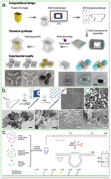
Figure 5. Examples of different DNA origami applications based on the 2D/3D shape. (a) Mold cast method [22], (b) TMAPS and TEOS silification process [23], (c) DNA origami hairpin for computation [24]. Figure (a) adapted with permission from [22], copyright 2014, AAAS. Figure (b) reproduced with permission from [23], copyright 2019, Wiley. Figure (c) reproduced with permission from [24]. Copyright 2017, Oxford University Press.
Download figure:
Standard image High-resolution imageThe mold-cast method is a demonstration of an indirect way to convert DNA origami shapes into nano-objects, which has, due to the indirect nature, its limitation when it comes to the size and accuracy of the shape. So considerable efforts have been made to establish ways to deposit materials directly onto DNA origami thus converting the biological shape into inorganic objects. Recently, such chemical modifications were shown by Heuer-Jungemann [23] and the Fan group [25]. In both cases, 2D and 3D DNA origami structures were silicificated by covering the DNA origami using N-trimethoxysilylpropyl-N,N,N-trimethylammonium chloride (TMAPS) and incubating then the DNA origami in TEOS (see figure 5(b)). TMAPS contains a positive quaternary ammonium group that binds to the negative DNA backbone and siloxane groups that react with TEOS. For example, Nguyen et al fabricated 2D rings and rods as well as 3D crystals using this method is illustrated in figure 5(b) [23]. The Fan group widened the range by silica coating of various DNA origami with different shapes (e.g. rectangle, triangle, cross, cube, hemisphere, toroid, ellipsoid). The coating layer thickness was characterized in the case of the DNA origami triangle and a mean thickness of 3.1 nm (z-axis) after 5 d of growth time was reported.
Static DNA origami structures can be also used to create nanoscale probes or measurement standards like the DNA origami force clamp with an entropic spring [26]. The length of the freely entangling ssDNA between the two arms of the DNA origami was varied, which produces a user defined entropic force, which can be approximated using the freely jointed chain model [27]. This system was used to study the conformational changes of a Holliday junction, which adopts two separate X-like conformations (iso I and iso II). The Holliday junction was formed using the ssDNA spring and three other oligos, where two of the oligos included a Förster resonance energy transfer (FRET) pair. The switching between iso I and iso II was probed by varying the length of the ssDNA spring and monitoring the corresponding single-molecule FRET signal. By decreasing the length and increasing the entropic force, the Holliday junction stayed more in the iso II state than in the iso I state.
Finally, another useful application of DNA arising from the shape and specific base pairing is molecular computing. Since innumerable amounts of DNA origami nanostructures can be fabricated in a single tube and each of those structures could in parallel perform logic operations or store digits, DNA origamis can offer systems with unprecedented computational power. However, as intended in nature the DNA acts as a 'read-out' memory to access vital information to preserve and procreate life thus missing the vital write-function, which is not enough for computation purposes. This has led into different approaches to tackle the matter. Chandrasekaran et al [24] demonstrated the idea of DNA computing by using simplistic, linear DNA origami-like structures figure 5(c). Here, the staple strands hybridize the scaffold without any crossovers, thus forming a linear dsDNA chain. There are 6 staple strands 600 bp apart from each other that include unique extensions (A0–A5). These extensions are designed in a way, that one strand at the end can be bridged with any other strand via a so-called data strand that is complementary to both extensions. Such a bridging strand forces the main DNA structure to adopt a loop conformation, where the circumference of the loop differs for each pair. These looped structures migrate differently in an agarose gel and form their own bands, which can be assigned to a single bit. Each data strand includes a toehold, which can be used in the strand displacement reaction to remove the data strand thus allowing the rewriting of the DNA structure. All these functionalities together formed a rewritable 5-bit system. Depending on the concentration of the data strands, the writing and erasing process can take minutes to hours.
2.2. Tuning of intermolecular interactions
2.2.1. Hierarchically organized materials
Since the early days of DNA nanotechnology there was the general aim to create extended well-ordered structures from DNA [28]. There are basically three types of interactions, which can be exploited for creating extended DNA origami networks (see figure (6)): (i) the specific hydrogen bonding between the nucleobases (Watson-Crick base pairing or in special cases also Hoogsteen base pairing) acting perpendicular to the DNA double helices, (ii) the unspecific stacking interactions due to π–π interactions between the aromatic systems of the nucleobases acting along the double helices, and (iii) electrostatic interactions, which exploit the negative charges of the DNA backbone.
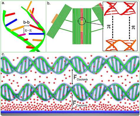
Figure 6. Overview of the different types of DNA origami interactions: (a) the specific hydrogen bonding between the nucleobase, (b) the stacking interactions due to π–π interactions between the aromatic systems of the nucleobase, and (c) electrostatic interactions, which are due to positive charges of dissolved ions (doubly charged positive ions depicted as red spheres) and negative charges of the DNA backbone and the surface (shown in blue).
Download figure:
Standard image High-resolution imageFormation of larger-scale hierarchically ordered DNA nanostructures using sticky ends and thus specific hydrogen bonding was already demonstrated by Rothemund in his original paper of 2006 (see figure 1) [7]. Several other examples have been published demonstrating hierarchical self-assembly of DNA origami units using extended staple strands serving as sticky ends thereby creating 2D networks of DNA origami ('2D DNA crystals') [29, 30]. A 3D crystal formed from tensegrity triangles connected by sticky ends was demonstrated and characterized at 4 Å resolution [5].
Formation of hierarchically ordered DNA nanostructures using stacking interactions is less obvious than the use of the specific hydrogen bonding, but it turned out to be very effective. Woo and Rothemund (for 2D) [31] and later the Dietz group (for 3D) [32] demonstrated how the unspecific π–π interactions can be turned into very specific recognition elements to assemble DNA origami nanostructures in a well-defined way into larger-scale structures. Woo and Rothemund equipped the rectangular 2D DNA origami with binary sequences of active patches (blunt ends) and inactive patches (scaffold loops without staple strands) along one of the rectangle sides [31]. This allowed to program specific interactions with other DNA origami rectangles to create chains of rectangles in a specific sequence. This was extended to microscale 2D arrays of DNA origami squares exploiting all four sides of the squares and in this way creating the concept of 'fractal-assembly' (see figure 1) [16].
The concept of creating higher order structures using stacking contacts based on shape complementarity was extended to 3D DNA origami by the Dietz group [32]. They created microscale filaments and lattices from 3D DNA origami components using shape complementary stacking contacts (see the stacking scheme in figure 1) [32]. The stacking contacts compete with repulsive electrostatic interactions, which can be tuned by the ionic strength of the solution allowing the construction of large-scale structures, which can be switched either by changing the concentration of cations in solution or by varying the temperature. Later, in 2017, similar strategies have been used to create planar rings of up to 350 nm in diameter, micrometer-long thick tubes and 3D polyhedral assemblies with up to 450 nm diameter and a molecular weight of 1.2 GDa (see figure 1) [8]. To achieve this, different DNA origami building blocks have been used (V brick, triangular brick and rectangular brick) to assemble different larger structures. The assembly pathway was controlled by introducing different self-complementary interfaces (matching blunt-end protrusions and recessions) to the V-brick and the self-assembly into larger structures is initiated by simply increasing the ionic strength of the buffer. By adjusting the strength of the interface binding, different brick binding processes could be initiated at different ionic conditions. For example, in the case of the planar ring made from V bricks, two side interfaces of the V brick were programmed to be complementary via ssDNA extensions leading into curved arcs and finally the full ring. The size of the ring could be controlled by altering the opening angle of the V brick (12.5°–30°). The tube assembles simply by including additional, weaker self-complementary parts to the top and bottom of the V brick that lead to stacking of the rings into a tube, but the transformation from the rings to tubes is only initiated by further increasing the ionic strength of the buffer. The length of the tubes could be more than 1 μm. Interestingly, a chiral twist could be introduced to the tubes by controlling the twist deformation of the V brick.
However, stacking contacts are based on non-covalent interactions, which can break at low cation concentration. To stabilize these stacking contacts, covalent bonds can be photochemically formed by placing a 3-cyanovinylcarbazol moiety on one blunt end next to a thymine on the opposite strand and blunt end [33]. Irradiation at 365 nm covalently couples the blunt ends through a [2 + 2] cycloaddition. Notably, the process can be reversed by irradiation with 310 nm light [33]. Stacking contacts have recently been used to assemble DNA origami molds into micrometer scale superstructures in order to create conductive gold nanowires [34].
2.2.2. Surface patterning and lithography
Within the past decade, a variety of organic and inorganic materials and molecules have found its uses in different surface patterning strategies [35, 36], and the creation of tailor-made optical, electrical and chemically modified surfaces has garnered a lot of attention. Especially attractive would be methods that allow patterning in micro- or even millimeter scale, which could lead into new electronic and optical applications or tailored surfaces with properties such as negative refractive index that are keys to future innovations. Current, established top-down methods to fabricate such tailored surfaces include electron beam lithography, UV lithography and nanoimprinting, which have their limitation when it comes to cost, scale and production rate.
To overcome these limitations, researchers have sought bottom-up methods based on molecular assembly and, unsurprisingly, DNA has been among the most prominent candidates due to aforementioned functionalization and up-scaling schemes. Here, the DNA origami is typically used either as programmable mediator for or inhibitor of chemical reactions to construct larger 2D and 3D assemblies and crystals. Combined with the DNA functionalization scheme, these larger assemblies could be used to fabricate metamaterials such as perfect lenses [37]. In 2017, a DNA origami breadboard based nanoimprinting method was demonstrated, where a rectangular DNA origami is programmed to contain thiol-modified staple strands in a predetermined pattern [38]. After depositing the DNA origami on a gold surface and denaturing the structure using NaOH, only the patterned, thiolated oligos are left on the gold surface. By introducing complementary DNA coated nanoparticles (5 or 10 nm in diameter), linear gold particle chains of predetermined size could be assembled on the gold surface. In principle, this method could be utilized on any surface, as long as the selective covalent linking between the modified oligos and the surface can be established.
Another example where DNA shapes could be used in lithography was demonstrated by the Toppari group [39]. The principle of this lithography process is DNA-assisted growth of silicon dioxide on a silicon layer that is on top of a sapphire substrate (figure 7(a)). The growth is facilitated by TEOS and ammonia reaction in a controlled humidity environment. In this case, the role of an arbitrarily shaped DNA origami deposited on a layered silicon-sapphire surface is to act as a mask to prevent growth of silicon dioxide, which results in a DNA origami shaped hole in the resulting SiO2 layer. By using standard lithography processes (PECVD Si etching, metal deposition, HF etching of SiO2 and Si etching) the holes could be converted into metallic structures with sub-100 nm size and the feature size down to 10 nm. Notably, since each DNA origami acts as a separate mask the process is parallel in nature and can be extended to the wafer scale. As an example, bowtie shaped metallic structures fabricated using this method were successfully used in SERS to detect bipyridine and rhodamine 6G [39]. Similar patterned surfaces can be also made using direct chemical modification of DNA origami, where silver atoms or ions are deposited onto the negatively charged DNA backbone of the DNA origami (Rothemund triangle) under UV exposure [40]. Since DNA absorbance is in UV range, the DNA origami acts as localized UV photosensitizers. The reduction process was carried out either in solution or on a silicon surface. The resulting structures were slightly higher (0.9–3.8 nm) and smaller in size (edge length from 150 nm to 90 nm) than the original DNA origami but retained the overall shape of it after 12 reduction cycles.

Figure 7. (a) TEM images of gold bowtie antennas fabricated using DNA-assisted lithography [39]. (b) Supporting lipid bilayer (SLB) assisted assembly of DNA origami crosses into hierarchical lattice structures [41]. (c) SLB assisted packing of Rothemund triangles into tight lattice formation [42]. (d) Surface assembly of non-twist-corrected (upper) and twist-corrected (lower) Rothemund rectangle [43]. (e) Stepwise monomer DNA origami assembly into larger hierarchical structure [44]. (f) Gold nanorod chain formation on a linear DNA origami (upper) and a similar structure after silver enhancement process (lower) [45]. (g) Schematic view of the assembly of rhombohedral DNA origami lattice (left) and TEM image of the lattice, when AuNPs have been positioned into the center of each triangular DNA origami building block [46]. Figure (a) reproduced with permission from [39], copyright 2018, AAAS. Figures (b) and (d) reproduced with permission from [41, 43], copyright 2015 and 2014, Springer Nature. Figures (c) and (g) reproduced with permission from [42, 46], copyright 2014 and 2018, Wiley. Figures (e) and (f) adapted with permission from [44, 45], copyright 2019 and 2017, American Chemical Society.
Download figure:
Standard image High-resolution imageThe previous examples demonstrate cases of large scale patterning, but due to the random nature of the deposition, they lack any mechanisms to arrange DNA origami into dense, well-defined arrays or any other predefined pattern. This is especially important in application such as nanoscale electric circuits on silicon wafers, where the distances between components, wires and contacts need to be well defined. One possible option would be just to upscale the DNA origami structures to micro- or millimeter size so they would naturally fill the surfaces. However, since the commonly used M13mp18 scaffold limits the size of individual structures, larger assemblies require a mechanism to selectively attach DNA origamis together. So considerable efforts have been made to develop methods to control the DNA origami deposition process and assemble larger constructs on the substrate during the deposition process.
One of the methods relies on self-organization of symmetrically shaped DNA origamis to lattices via surface migration and end-to-end interactions. In general, for visualization of any DNA origami structure, they are immobilized on the surface via Coulombic and van der Waals interactions. Magnesium is commonly used to attach the DNA origami to either the negatively charged silicon or mica surface. However, if DNA origami is only weakly bound to the surface and allowed to migrate, then it can interact with other loosely bound DNA origamis on the substrate. For example, introduction of monocationic salts such as sodium in non-excessive quantity to magnesium buffers typically weakens the binding of DNA origami enough to allow for surface migration. By guiding the interactions of DNA origamis on the surface via clever designing, hierarchical assemblies can be formed.
There exist several publications on the matter. One way to cover large surfaces using different 2D DNA origamis was developed by Suzuki et al [41]. Here, the surface was coated with a supporting lipid bilayer (SLB) using a synthetic zwitterionic lipid 1,2-dioleoyl-sn-glycero-3-phosphocholine (DOPC) to enable the weak ionic interaction between the surface and DNA origami in the presence of Mg2+. The concentration of DNA origami was found out to be crucial for the formation of the arrays. As an example, plus-shaped DNA origamis with planar, blunt-ends was used to form a DNA origami array with the periodicity matching the size of the DNA origami (figure 7(b)). Another lattice scheme involved the same DNA origami, but here the blunt-end stacking was prevented by 12 T4 ssDNA extensions protruding from the blunt-ends. This configuration caused the DNA origami to adopt a close-packed DNA origami lattice (figure 7(b)). In the same vein, DNA origamis were organized on a mica surface in large 2D arrays with different packing densities [42]. Similarly as before, Mg2+ ions were utilized in the immobilization, but introduction of sodium ions (200 mM) during the deposition process weakens the interaction between mica and DNA origami so that the DNA origamis can diffuse along the surface. Depending on the shape and interactions between the DNA origamis, they would rearrange into certain array formations. As an example, the Rothemund triangle adopted very high packing density (figure 7(c)). The study done by the Rothemund group [43] sheds more light onto the requirements to form the arrays. They demonstrated that the assembly of DNA origami into hierarchical patterns on a mica surface depends on the fractional surface density of the divalent cations as well as the DNA origami design and surface properties of mica rather than the solution bulk divalent cationic concentration. For example, non-twist-corrected, rectangular DNA origamis that bound from the edges via blunt-end stacking favoured 2D lattices while the twist-reduced ones favoured linear chains (figure 7(d)).
More recently in 2019, the assembly by surface diffusion was further developed by the Bae and Liedl groups [44]. As before, concentrations of mono- and divalent cations were adjusted to control diffusion of Y-shaped DNA origami monomers on SLB-mica or SLB-glass surfaces. By adding sets of linker oligonucleotides, the monomers can be assembled into three-legged triskelion DNA origami (see figure 7(e)). Furthermore, the triskelion can be arranged to a hexagonal lattice by addition of another set of oligos. Both of these processes were shown to be largely dependent on the mono- and divalent cation concentrations. To study the assembly and kinetics, the surface diffusion of the dye-tagged monomers were tracked in a total internal reflection fluorescence (TIRF) microscope setup in real-time. The diffusion behavior of the monomer was shown to adopt two distinct populations in both high NaCl (150 mM) and low MgCl2 (5 mM) concentrations and slow down or virtually stop in both low NaCl (0 mM) and high MgCl2 (5–20 mM) concentrations on both surfaces. However, the diffusion coefficients of the monomers differed between mica and glass. This finding allowed the authors to characterize the assembly of the higher order structure by so-called stop-and-go manner: DNA origamis would be bound to the surface and let diffuse in high NaCl and low MgCl2 conditions, hybridization oligos would be injected and structures are allowed to form larger assemblies, then the process would be stopped by switching the cation concentration and finally the outcome is characterized similarly as before. Then by switching again the cation concentrations and introducing the next set of oligos, the hexagonal DNA origami could be formed. The triskelions and the hexagons were assembled overnight, which resulted in mostly correctly folded DNA origamis.
So far we have only considered surface coating by DNA origamis, but due the site-specific functionalization scheme the patterning can be executed on the DNA origami itself. Early examples include the proof-of-principle of placement of streptavidin [47] and carbon nanotubes [48], while the more application oriented assemblies were done by combining plasmonic nanoparticles and DNA origamis. An example of this was demonstrated by Lan et al [49]. Instead of single DNA origami as platform, a stacked assembly was utilized, where single rectangular DNA origami is programmed to bind from both sides to single gold nanorods with defined angle between the rods. By mixing DNA origamis and nanorods in different ratios and choosing the angle between the rods to be −45° or 45°, 3D nanorod helices with either left- or righthanded chirality and tunable length could be fabricated and the structures showed strong chiral response around 700 nm. In another example, 17 nm wide and 410 nm long linear DNA origami was used to arrange AuNRs in one long chain [45]. Here, the electrostatic interaction in the presence of Mg2+ was utilized to glue the particle to the DNA origami, which resulted on average in 11 aligned and one or two misaligned rods on a single DNA origami (figure 7(f)). To close the unwanted gaps, the AuNRs were grown larger using an electroless plating solution, where the electric characterization of the grown nanowires showed that the resistivity of the wires could be as low as 8.9 × 10⁻⁷ Ωm, which is already close to the resistivity of bulk gold.
On a last note, the presented, patterned structures have been relatively small or required a supporting substrate to form. However, more recently, progress has been made to build even larger assemblies, up to the Gigadalton range as is described in more detail in section 2.1. Another notable example of a 3D DNA origami lattice was demonstrated also by the Liedl group [46]. Here, the authors connected together three 14-helix bundles (14HB) to form monomeric, triangular building blocks, that were further assembled into a larger rhombohedral lattice via shape complementary blunt end interactions between different 14HBs (see figure 7(g)). The resulting crystals were polycrystalline in nature and tens of micrometers in size, where the lattice spacing between monomer subunits was 64 nm. The authors also functionalized each building block with single AuNPs (10 or 20 nm) and could show using SEM and small-angle x-ray scattering (SAXS) that the particles were arranged into the rhombohedral configuration.
2.3. Site-specific chemical functionalization of DNA origami
One of the key components of the DNA nanotechnology is the ability of DNA to incorporate a vast number of different functional groups like organic molecules (e.g. fluorescent dyes), polymers, proteins and nanoparticles, as has been and will be discussed. The most simple functionalization of DNA origami is the introduction of single stranded overhangs, which can serve as sticky ends, not only to create links to other DNA origami structures as was discussed above, but also to attach functionalized DNA, as is outlined in figure 8. In the following, we want to outline the basics of DNA functionalization and different strategies to attach various functional groups to DNA. When looking at DNA as a whole, modifications can be done either at the end of the nucleotide chain or internally, and more specifically the bases, the sugars, and the phosphate backbone can be modified. However, the sugars are challenging to modify chemically and the modifications on the bases might disrupt the DNA hybridization, so typical targets for modifications are the end of chains and the phosphate backbone.
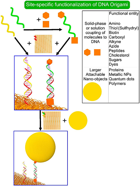
Figure 8. Site-specific functionalization of DNA origami can proceed through hybridization of chemically modified DNA with extended staple strands. DNA strands can be functionalized at both ends with different functional groups, the most common of which are listed in the table on the right. The chemical modifications of DNA also provide access to functionalization with proteins, nanoparticles, polymers, etc.
Download figure:
Standard image High-resolution imageFor the end of chain or terminus modification, two commonly used strategies exist [50]: (i) solid-phase functionalization and (ii) solution coupling functionalization. Actually, solid-phase synthesis and functionalization of oligonucleotides are interlinked, since functionalization is carried out during the synthesis. In solid-phase functionalization DNA is attached to a support that is typically either controlled-pore glass or polystyrene and the solvent and reagents can be introduced and removed quite easily from the system. The oligonucleotide synthesis is executed by binding a single nucleotide to the pore, either from 3'‐ or 5'‐end, and attaching the next nucleotide to the chain in a cyclic reaction process, which is typically based on phosphoramidite chemistry that is sensitive to water and oxygen and therefore utilizes anhydrous conditions. Currently, the processes are fully automated using DNA synthesizers with affordable prices. While having high coupling efficiency, this tactic limits somewhat the range of the available functional groups. The most typical chemical groups that can be attached are the amino group, thiol and biotin. Typically, 3'-to-5' synthesis is employed due to more affordable price, and both 3'- and 5'-ends can be modified. However, in the case of the 3'-end the functional group should already exist before the beginning of the sequencing, which again limits the range of possible modifications and possibly the yield. Although the coupling efficiency is high, the end product usually has some variety in the length and this problem is more pronounced as the length of the desired sequence is increased. Therefore, purification methods need to be applied after the DNA synthesis, which can decrease the yield of the final product drastically.
Due to drawbacks of low yield, the requirements to use harsh chemicals limiting the available functional groups, an effective limit to 3'-to-5' synthesis and the need for the support being inert, the solution coupling offers an alternative route to efficiently attach hydrophilic groups to DNA. As the name suggests, the reactions are carried out in aqueous solution using different chemistries, where popular methods include the amide bond formation via conjugation of amines with N-hydroxysulfosuccinimide (NHS) esters, coupling of thiols with maleimides via a Micheal addition, and click chemistry using alkyne end-modified DNA and azide modified target [51].
Attachment of more complex entities such as proteins and nanoparticles (e.g. Au and Ag nanoparticles and semiconductor quantum dots) requires more careful consideration of the experimental conditions. The available schemes can be divided roughly into three categories: (i) non-covalent binding, (ii) binding without protein engineering (non-site specific), (iii) covalent binding and protein engineering combined (site-specific). Non-covalent coupling can be achieved using biotin-streptavidin, aptamer-protein, antigen-antibody or NTA-Ni2+-Histag interactions, to name a few. Use of biotin and streptavidin is especially popular, since solid-phase functionalization can be used to tag the oligos with biotin and proteins and nanoparticles can functionalized with streptavidin [15] and it requires only mild buffer and temperature conditions. However, the drawback with non-covalent interactions is its reversibility, which can make covalent binding the more appealing option.
Covalent binding can be achieved e.g. by using heterobifunctional crosslinkers with two reactive groups at opposite ends. An example is succinimidyl-4-(N-maleimidomethyl)-cyclohexane-1-carboxylate (SMCC) having maleimide as a thiol-reactive group on one end, and an NHS ester as an amine reactive group at the other end. In this way, lysine side chains of a protein can be linked to thiolated DNA. Several other heterobifunctional cross linkers exist that are commercially available and utilize relatively mild condition in the crosslinking and do not require protein engineering. It is also possible to use modified proteins before the coupling. For example, proteins mutated with azide groups (azido-proteins) can be linked to alkyne-modified DNA via the copper catalyzed click chemistry. However, due to toxicity of Cu(I) and possible enzyme losses due to copper, copper-free azide click chemistry has been developed, where dibenzocyclooctyne (DBCO) functionalized DNA is bound to the azide-protein [52]. Covalent coupling also includes the bonding of thiols to Au or Ag, which is the most common method to attach Au or Ag nanoparticles to DNA. An overview of possible chemical functionalities that can be introduced to DNA are listed in figure 8.
3. Functions of DNA origami nanostructures
In the previous chapter we defined the core properties of DNA origami: the 2D/3D shape, the possibility for site-specific functionalization and tunable intermolecular interactions. Different functions can be attained thought these properties (figure 3). Over the past years, researchers have incorporated these functions into the DNA origami, which has expanded the use of DNA origami into a multitude of different fields that are not just limited to biology and medicine. Besides the function directly, other considered aspects are the scale where the DNA origamis are utilized (microscale vs macroscale) and the controllability or responsiveness of the DNA origami system (static vs dynamic, see figure 2). These two aspects have some historical significance, since while most of the past research has concentrated on fabricating individual DNA origami based nanodevices and platforms containing unique properties, new research topics such as programmable surface and hierarchical superstructures are on the rise due to promises of more sophisticated innovation. In this chapter, we would like to flesh out some of the most recent advances in these fields and give an outlook for future prospects.
3.1. Patterning on DNA origami
Due to the precise positioning of functional groups and molecules on DNA origami and the programmable self-assembly, DNA origami can be a powerful tool in research fields that utilize sensing (biological and chemical sensing as well as diagnostics) or pattern recognition (e.g. for nanostandards, nanorulers or diagnostics). In the past, different methods like optical spectroscopy and standard biochemistry assays have been utilized successfully to detect chemical and biological analytes, but key aspects like multiplexing and discrimination of closely related species can still be challenging. Meanwhile, the DNA origami offers innovative solutions to tackle these issues [53, 54].
A general detection scheme is based on either binding of a molecule to DNA origami driving it to adopt a certain state, or the DNA origami is used as platform to bind molecules in certain patterns. In the past, examples include DNA origami nanopliers by Kuzuya et al [55], where the DNA origami can fluctuate between different shapes, but adopts the least energetically favourable shape due to binding of a target molecule to the DNA origami. In this case, the readout can be done using either AFM or fluorescence spectroscopy.
A slightly different approach, which also uses molecule patterning on DNA origami, was used by the Bald group [56], who studied the single strand breaks (SSB) of radiosensitizer modified DNA sequences under vacuum UV irradiation (8.44 eV). A triangular DNA origami was used as a platform to position streptavidin (SAv) in certain predetermined pattern (figure 9(a)). The binding of SAvs was via biotinylated ssDNA extensions protruding from the DNA origami. The influence of 5-bromouracil (5BrU) and 8-bromoadenine (8BrA) radiosensitizer on the SSB of different DNA sequences was studied extensively by irradiating the DNA origami without the SAv and then attaching SAv to the DNA origami and counting the present SAvs. The absence of expected SAv in different positions was correlated to the breaking of ssDNA linker in those positions. The same technique was also used to quantify electron induced SSB in telomeric DNA [57] and other DNA sequences containing radiosensitizers that are of potential use in cancer radiation therapy [58, 59].

Figure 9. Examples of different DNA origami applications. (a) Rothemund triangle in studies of radiosensitizers. Biotin containing ssDNA extensions are placed in a distinct pattern and after UV or low-energy electron (LEE) exposure and subsequent streptavidin binding the strand breaking can be detected as missing streptavidins [56]. (b) Nanometer scale DNA origami standard. Two sets of ssDNA extension for dye-tagged oligo attachment are placed certain distance away (32.5 nm or 65 nm), which can be visualised in fluorescence microscope. The histogram shows calibration results of three different samples for both distances [60]. (c) MicroRNA (miRNA) detection on rectangular DNA origami using DNA-PAINT. Extensions are placed in an array, where certain position are used for orientating the pattern (boundary markers) and others for detecting the analytes. The miRNA binds to the base of the extension, allowing imager strands to bind to the 7 nt section at the end of the extension. The fluorescence microscope images show a single array before and after miRNA incubation [61]. (d) Schematic view of mechanochemical DNA origami probe. Six DNA origami tiles are connected together via scaffold crossovers and dsDNA locks (dsDNA 1–6). The ends of the assembly are connected to optical tweezers. The full assembly is shown in the AFM image. The locks can be opened by either exerting enough force or introducing a target molecule [62]. Figure (a) reproduced with permission from [56], copyright 2019, Royal Society of Chemistry. Figure (b) reproduced with permission from [60], copyright 2018, Springer Nature. Figures (c) and (d) reproduced with permission from [61, 62], copyright 2018 and 2014, Wiley.
Download figure:
Standard image High-resolution imageDNA origami triangle platforms have also been used to create nanoarrays of small pharmacophores to detect single biomolecular binding events by AFM [63]. DNA origami triangles were decorated with different protein binding ligands at well-defined positions and distances to each other to determine binding yields for monodentate and bidentate binding to the proteins trypsin and AGP. This technique might be used in the future to enhance the throughput of drug screening.
DNA origami offers unprecedented control of structures on the length scale from 1 nm to 100 nm, which provides unique possibilities to serve as standards and probes in superresolution microscopy by carrying patterns to be optically recognized. A specific method of superresolution microscopy is DNA-PAINT, where short, dye labelled oligonucleotides are reversibly bound to DNA structures, which causes highly localized fluorescence blinking. One advantage here is that the dye modified strands are coming on and off the DNA platform so that fresh dyes are constantly supplied to the system and the problem of photobleaching is significantly reduced. DNA-PAINT could be especially useful for imaging multiple targets (multiplexing). One way to utilize DNA-PAINT for the development of a DNA based nanoscale distance standard is illustrated in figure 9(b) [60]. Two spots on a rectangular DNA origami, both including sticky end extensions to hybridize DNA strands, were designed to be 32.5 or 65 nm apart from each other (center-to-center distance). This distance was measured in a TIRF microscope setup using a camera with a calibrated pixel size. The experimental values for the longer and the shorter distance were 59.0 nm and 29.1 nm, respectively. The differences between the experimental and the predicted values were attributed to possible sample tilting or bending of the DNA origami.
More recently, Xu et al [61] developed a pattern recognition scheme to detect microRNAs (miRNA) using DNA-PAINT and DNA origami. In contrast to the previous case, here the binding of individual analytes via DNA hybridization is used to create unique patterns that are detectable in fluorescence microscopy (figure 9(c)). A rectangular DNA origami was used as a platform with 12 sticky ends protruding from it. These 12 ends formed a 3 × 4 pattern, where 4 of the strands were used as boundary indicators to highlight the orientation of the DNA origami (4 spot pattern). The rest 8 strands were used to hybridize arbitrary miRNAs. The system acts as a barcode, where binding of different miRNAs will leave different patterns on the 3 × 4 array and the limiting factor for the array size is the 6 nm distance between the binding sites. The readout is executed by binding fluorophore-labeled strands to the miRNAs, which will form an asymmetric and unique pattern in DNA-PAINT imaging. The authors used this scheme successfully to detect 8 different miRNA in either 30 or 100 pM concentrations.
Besides the patterning on DNA origami, hierarchical DNA origami assemblies can be also employed in analytics. One of the recent study showed a mechanochemical DNA origami probe (figure 9(d)) [62], which consists of seven interconnected DNA tiles that together form a 7-tile chain. One edge of each tile is connected to the adjacent via scaffold cross overs and the other edge has user-defined locking mechanisms (figure 9(d), dsDNA 1–6) that is designed to be unlocked using a target biomolecule. The last and the first tile in the chain are connected to optical tweezers via dsDNA handles. The locking mechanisms included either strand displacement or aptamer binding reactions, where the dsDNA connecting two tiles is opened by introduction of a target DNA strand or the aptamer. By opening the locks, the DNA origami structure extends longer, which can be seen as jumps in the (force) vs (distance between beads) curves when pulling the DNA origami from both ends using the optical tweezers.
3.2. Actuation and (reversible) switching
Recently, DNA origamis have been used to create nanomotors and actuator, either as platform to incorporate naturally occurring actuators or directly as the motor. Besides the advantage of self-assembly and readily available chemical modifications compared to the other biomolecules, DNA origamis have also advantage over many inorganic materials due to difficulties to incorporate naturally occurring motors to such materials without e.g. buffer layers or protection in between [64, 65], whereas DNA origamis can readily incorporate many of the nature's wonders. Here, the DNA origami based applications have been numerous in respect to the nature of the bidirectional signaling, the scale of the used system and the work produced, so we will try to provide an overall picture of the different aspects realized thus far. There are several ways to categorize the DNA origami actuators such as the produced output signals, the potential applications or the scale of the system, however, the chosen division is based on the used external stimuli driving the system, which include strand displacement reactions, incorporation of thermo- or EM radiation-responsive chemicals, motion of biomotors, pH induced structural changes, Coulombic and magnetic interactions and drying-liquid flow.
The strand displacement is a process occurring in nature [66] making it one of the more robust ways to cause motion in DNA structures. In strand displacement reactions, the DNA structure is designed so that there exists at least one dsDNA sequence that has an unhybridized ssDNA sequence next to it, a so-called toehold ssDNA strand/sequence. The dsDNA section is comprised of a static strand connected to the toehold and a strand-to-be-replaced. If a DNA strand fully complementary to toehold plus the static strand (so-called fuel strand) is introduced into the solution, this strand will first bind to the toehold and then replace the strand that is wanted to be removed. One of the past examples of strand displacement driven DNA origami systems include work by Gu et al [67], who created DNA origami-based walker systems, where a DNA tensegrity-triangle walker travelled along a predetermined path on a DNA origami template fueled by strand displacement reactions. Along the way, the walker also selectively collected or donated different nanoparticle cargos based on the introduced fuel strands.
A recent example of movement through strand displacement reactions is shown in figure 10(a) [68]: a gold nanorod (35 × 10 nm, AuNR) is set in motion along either a 2D rectangular or 3D triangular DNA origami surface and motion was tracked by measuring the circular dichroism (CD) response of the system comprising a stationary AuNR bound to the DNA origami and the moving AuNR. Initially the moving rod is bound by two rows of binding strands and the motion is induced by systematically dehybridizing the strands behind the rod and freeing the strands in front of the rod with two different fuel-strands. This results in stepwise manner motion, where the rows behind the rod are blocked, the rows in front are freed and the rod is always bound in one row. Each step took 15 min and CD response showed bisignate spectra around 725 nm. One key feature here is the reversible motion of the nanorod, which can be facilitated by introduction of appropriate strands [68].
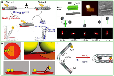
Figure 10. Examples of different DNA origami applications. (a) Strand displacement based DNA origami actuator. Gold nanorod is moved on rectangular DNA origami platform by selectively detaching the rod from the backrow of ssDNA extensions (row A) and binding the rod to the row in front of it by removing the blocking strands (row C). The reverse binding back to row A is prevented by introduction of blocking strands. Each strand on the DNA origami contains a toehold configuration for the strand displacement [68]. (b) Schematic view of DNA origami flap actuator. Two AuNPs are bound to the flap and the ring and the flap is connected from one side to the ring via ssDNA extensions. The flap can be withdrawn by introduction of a fuel strand that causes the ssDNA extension to adopt shorter, coiled dsDNA. Since the nanoparticles are coupled, the flap movement can be detected as localized surface plasmon resonance shift [69]. (c) Magnetically driven DNA origami actuator. The base of the actuator is formed out of a hollow brick (green DNA origami) and a rectangular base that are connected via ssDNA overhangs. The TEM and AFM images show the base assembly. The full assembly includes a DNA origami arm that is made from similar brick DNA origamis, where the end of the arm contains digoxigenin labeled strands to bind a superparamagnetic bead (bottom figures). The full motion of the actuator in a precessing external magnetic field with a frequency of 1 Hz is shown in the brightfield images [70]. (d) Reversible temperature induced switching of a DNA-pNIPAM hybrid structure [71]. Figures (a) and (c) reproduced with permission from [68, 70], copyright 2015 and 2018, Springer Nature. Figure (b) reproduced with permission from [69], copyright 2015, Royal Society of Chemistry. Figure (d) reproduced with permission from [71], copyright 2018, Wiley.
Download figure:
Standard image High-resolution imageA newer example of a switchable, strand displacement driven plasmonic system consists of a 3D DNA origami assembly, where two 14-helix bundles are connected together from the middle via the scaffold strand and a single AuNR is attached to both bundles [72]. Due to the scaffold connection, the two bundles can freely rotate along the central axis and together they form an X-shaped plasmonic system, where the handedness depends on the angle between the rods. Moreover, the handedness of the system is switchable using a set of locking and removal strands so that the angle can be fixed to either left- or righthanded configuration. A relax state is adopted, if all the locking strands are removed. In the measurements, the assembly had left- or righthanded tunable bisignate CD response around 750–800 nm and the timespan of the switching was roughly 15 min from relaxed, non-CD response to full CD response.
Besides CD response, also plasmonic coupling of metallic nanoparticles can be used in monitoring the motion of nanoactuator systems, like in the case of the disc-shaped DNA origami actuator in figure 10(b) [69]. Here, the DNA origami consists of a movable flap in the middle and the surrounding ring. Two AuNPs were positioned into disc shaped DNA origami, one to the flap and the other on the ring next to the first particle, so that the particles form a coupled system with a specific plasmon resonance. The ssDNA linker between the flap and one side of the ring could be shortened using a fuel strand, thus pulling the flap away from the particle on the ring and changing the plasmon resonance. Additionally, the flap could be returned back to the original position via dehybridization of the target oligo by a removal strand.
Another example of strand displacement based actuators is the Bennett linkage frame consisting of four sides and four hinges that can reversibly change conformation from compact to open and vice versa by introduction of bridging ssDNAs strands [73]. In the same study, two different nanoscale crank-slider machines were fabricated and the motion of the sliders under thermal fluctuation was analyzed, but no external stimuli were used to control the motion of the machines.
Although the response time is quite low, the strand displacement based nanodevices are often quite robust and the cycling is repeatable up to a point: the literature reported strand displacement steps ranging from 3 [74, 75] to 32 [76], where overtime buildup of leftover fuel strands is attributed to be one of reasons why the strand displacement reaction based motors freeze [76]. It is also possible that systems form a so-called trap state, especially in the case of DNA walkers, where the desired interaction between two strands is blocked by unwanted binding fuel strands to both of these strands. In contrast, magnetically and electrically guided systems offer higher switching rates. Figure 10(c) shows magnetically driven DNA based nanoactuators [70]: nanoscale rotor systems. The elementary parts of the rotor consist of a hollow brick DNA origami (green tube) connected to a rectangular DNA origami via ssDNA overhangs and a lever-arm, which contains several, interconnected end-matching bricks. The arm was attached to the rotor via hybridization. To produce the motion, these assemblies were bound to streptavidin coated surface via biotin-ssDNA overhangs in liquid. The motion of the rotor was induced by attaching a superparamagnetic bead to the free end of the lever arm via digoxigenin labeled strands and applying a precessing external magnetic field. The tracking of the motion was observed in brightfield mode. The rotation could be controlled up to 1 Hz consistently (see figure 10(c)). By applying an external, non-rotating magnetic field, the position of the lever could be controlled with 8° accuracy against the fluctuation due to Brownian motion, allowing 45 distinct angles or states for the rotor.
One attribute often discussed only in a biological context is the relatively high negative charge of the DNA molecule. Due to the phosphate backbone, magnesium is often employed to reduce the Coulombic repulsion in the duplex DNA. However, this localized negative charge could be used to produce motion in presence of external electric fields. In the past, it has been shown that electric fields in liquid media could be used to dehybridize λ-DNA [77]. On a smaller scale, the concept of electric field guided DNA actuators was furthered by Kroener et al [78] and Kopperger et al [79]. The system developed by Kroener et al is in a sense quite straight forward since it contains a DNA origami lever (6HB) attached to a gold electrode surface, where the lever angle is controlled via the electric field. Here, the motion is induced by the negative charge of the DNA under the influence of an external electric field in solution. The free-end of the lever was functionalized with fluorophores, which are quenched close to the metal surface, i.e. when the lever is pulled close to the surface, resulting in an angle dependent fluorescence intensity. In the experiment, the gold surface and counter-ITO above it were biased with square-wave voltage (±0.2 V, 0.2 Hz) and a similar square-wave behavior in the fluorescence signal was observed, indicating that the immobilized 6HB is switching between upright and laying-down positions, with the rotation time of 100 μs. In the same vein, Kopperger et al used rotating electric fields to turn a 411 nm long DNA arm on a DNA origami platform [79]. In their experiments, the motion of the arm was tracked using either FRET pairs (one in the arm and others on specific point in the platform) or TIRF microscopy. The results showed consistent circular motion in respect to the rotation frequency of the electric field (from 1 up to 25 Hz).
Temperature can be used in a non-hybridization fashion to produce motion in DNA origami systems thanks to the site-specific functionalization that allows incorporation of thermo-responsive materials. One such material is the polymer poly(N-isopropylacrylamide) (pNIPAM), that converts from hydrophilic to hydrophobic when the temperature is increased above 32 °C and reversibly returns back when the temperature is cooled below 32 °C. This transition causes the molecule to contract and relax, respectively. Figure 10(d) shows a pNIPAM based DNA origami nanoactuator [71] consisting of two-armed DNA origami that has a flexible hinge between the arms. On both sides of the hinge, 3 pNIPAM modified oligos were attached in mirror symmetry. When the temperature is increased, the pNIPAM will turn hydrophobic and the arms attach to each other. This caused the DNA origami to adopt a closed position, which can be opened by lowering the temperature below 32 °C. The motion of arms can be tracked using fluorescence spectroscopy by functionalizing one arm with a Cy5 dye and the other with 16 nm AuNP.
Incorporation of naturally occurring motors and DNA has garnered interest. For example, Derr et al [80] developed a kinesin-dynein based motor system on tubular DNA origami and studied the motion of the tubular system. The Dynein or Kinesin was loaded on tubular 12-helix bundle DNA origami in chain-like fashion: 1–4 dynein or kinesin along the tube and Tamra molecules at the end of the tube were attached via sticky ends. The motion of the hybrid system was tracked using TIRF spectroscopy. It was shown that the differently functionalized DNA origamis migrated to opposite direction. In addition, introduction of both proteins on a single DNA origami resulted in decrease in velocity due to competing forces.
Actuation based on pH changes offers experimentally rather simplistic route, only requiring to change the condition of the used buffer, but the key issue is then the stability of DNA origami. As will be discussed in section 4, DNA origami is more or less stable in the pH range from 4 to 9 and going above or below causes chemical modifications in the DNA structure. However, such modifications can be used to one's advantage. An example of this was demonstrated by Ijäs et al [81]. The authors designed a DNA origami nanocapsule (dimensions = 31 × 28 × 33 nm) containing a lid and a body, both with a cavity inside (dimensions = 11 × 12 × 13 nm), linked via four ssDNA hinges so that the capsule can freely open (figure 11(a)). All along the edge of the lid and the body, ssDNA extensions and complementary dsDNA hairpins are positioned so that by lowering the pH the ssDNA and dsDNA form triplex DNA via Hoogsteen bonding thus closing the nanocapsule. The opening can be then facilitated by increasing the pH. The conditions for closing and opening or the transition pH value can be adjusted by adjusting the T-A-T base triplex content of the latches. The closing process usually takes several hours, whereas the opening happens quite rapidly, under 30 s. As model cargo, 5 nm AuNPs and horseradish peroxidase (HRP) enzymes were successfully loaded into the cavity of the nanocapsule (see figure 11(a)). Furthermore, the authors showed that HRP retained its functionality by tracking the ABTS oxidation reaction in presence of H2O2.

Figure 11. Examples of different DNA origami applications. (a) pH-controlled Lid-body DNA origami actuator. The lids contain either ssDNA or dsDNA-hairpin extensions, that form triplex DNA helices in right pH conditions. The TEM images on top-right shows the box in open configuration. The lower-right schematic and TEM images show an open box with cargo (5 nm AuNP) and a closed box with the same cargo [81]. (b) pH-switchable DNA origami mesh. The mesh containing single biotinylated ssDNA extensions is tethered from biotinylated-BSA coated glass surface via streptavidin intermediary. The AFM image shows meshes on mica. The ssDNA extensions (9 nt) are located on three, non-adjacent sides of the hexagonal mesh, and the conformation of the mesh can be visualized in a fluorescence microscope by introduction of dye-labeled oligos that bind to the extensions. For each individual mesh, based on the fluorescence unbinding and binding events of oligos, centers of three edges, the center of the mesh were solved and based on this the radius was calculated. From the radius data and the fluorescence microscopy images, different states could be identified. The three histograms (radius of the mesh vs frequency) illustrate three commonly observable modes: contracted mesh (left), spread mesh (mid) and spread dimer mesh (right) [82]. (c) Schematic view of chemical reaction driven DNA origami nanoscissors. Two AuNRs are attached to two interconnected DNA origami bundles, forming an X-shaped plasmonic chiral system. Depending on the irradiation wavelength (UV vs VIS), the two azobenzene-modified ssDNA extensions (red) either hybridize or dehybridize due to azobenzene transition to either cis- or trans-conformation, which changes the state (angle) of the DNA origami from locked to relaxed. TEM image shows the assembly in a relaxed state. The CD spectra show a bisignate CD response in locked state and non-CD response in relaxed state [83]. Figure (a) adapted with permission from [81] (https://pubs.acs.org/doi/10.1021/acsnano.9b01857, further permissions related to the figure should be directed to the ACS), copyright 2019, American Chemical Society. Figure (b) reproduced with permission from [82], copyright 2019, Wiley. Figure (c) reproduced with permission from [83], copyright 2016, Springer Nature.
Download figure:
Standard image High-resolution imageA different chemical or structural change can be facilitated using i-motif sequences, which are C-rich ssDNAs that fold into self-intercalating, compacted, quadruplex secondary structure at low pH. The process is reversible and the sequence returns to its original configuration by increasing the pH. LaBean group [84] demonstrated this concept by connection of two rectangular DNA origamis from one side via 6 i-motif staple strands. During the buffer exchange, surface-bound DNA origamis were incubated 5 min and washed 3 times with an appropriate pH buffer. By lowering the pH from 7.4 to 5.4, the length of the assembly decreased from 44.9 nm to 42.9 nm. This is in agreement with the theoretical open and closed states of 47.2 nm and 41.9 nm, respectively, since the length of the DNA origami in the open state can freely fluctuate.
A third example of a pH driven DNA origami actuator is shown in figure 11(b), where a tethered, hexagonal DNA origami mesh could be switched between a contracted and spread state by using BSA and changing the pH of the buffer [82]. In EDTA/MgCl2 buffer and tethered via biotinylated ssDNA to a streptavidin coated surface, the DNA origami adopted several states, corresponding mainly to a contracted state with 15 nm average radius, an extended state with 40 nm average radius and superpositions of the two states (see the histograms and the DNA-paint images in figure 11(b)). Untethered structures did only exhibit the spread state indicating that the core reason for the switching lays in the interaction between the streptavidin surface and the structure. In a buffer mimicking blood plasma, the DNA origami could be switched to either state by altering the buffer condition between pH 7.9 and low calcium concentration (2.5 mM) and pH 8.4 and high calcium concentration (2.5–5 mM) in a time span of 30 min.
In the same vein, reversible switching of a telomere-like DNA strand into a G-quadruplex using K+ ions and back into the linear form using crown ethers was demonstrated on DNA origami [85]. The G quadruplex switch was integrated into a photonic wire consisting of up to four fluorescent dyes, and could reversibly switch on and off a corresponding FRET cascade.
Liquid flow as mode of transportation is as old as life itself. From water mills to modern day microfluidics channels, the flow could be harnessed to produce work or transport chemicals and entities from point A to B. Although there are some publications in the DNA field [86] regarding liquid flow actuators, the DNA origami based flow actuators are quite scarce, but there are some examples like by Schreiber et al [87]. A 24-helix bundle was used as scaffold to position AuNPs in a left-handed helical spiral pattern that produces a controlled CD response. These assemblies were attached to a glass surface from one end of the bundle and by drying and resuspending to buffer the alignment of the helical assembly could be switched from horizontal to vertical position, respectively, which produced different CD response. Although simple drying and resuspension was utilized here as input signal, the same motion could be produced using an electric and magnetic field, non-drying liquid flow or optical tweezers to name a few.
Transformation of molecules can also be used to produce motion. A suitable type of molecules is azobenzenes, that reversibly change from trans- to cis-form under UV or visible light illumination, respectively. This transformation or motion of azobenzene can be employed in the DNA hybridization by inducing stress/twisting to duplex DNA or moving two strands close to each other so that the hybridization can take place. One example of this is shown in figure 11(c), where the conformation of DNA origami nanoscissors, containing one AuNR on each arm, was switched from open to closed state and back [83]. The motion is induced by hybridization and unfolding of two azobenzene modified DNA extensions, one in each arm of the scissors, which can be controlled by simple illumination either with UV (360 nm) or visible (450 nm) light. However, due to base-pairing, an elevated temperature (40 °C) was required to efficiently unfold the DNA extension. The angle between the two arms could be switched from 90° (relaxed state) to 50° (closed state) by 10–15 min illumination. The CD spectra of both states were characterized and the relaxed state was observed to be devoid of any CD response while the closed state produced a clear bisignate CD response.
3.3. Carrying/transporting
Nanosized carriers have been a hot topic for decades, especially in the field of biology, medicine and diagnostics [88]. However, in these fields the requirements for non-toxicity and a low immune response has limited the selection of viable materials. Due to the multifunctionality, sequence specific hybridization and self-assembly, carriers made of DNA offer better biocompatibility and selectivity towards cancer cells compared to lipids, polymers and nanoparticles. One especially attractive option is to use them as clinical tools, where for example multidrug resistance (MDR) is a prominent problem and would require more than one mechanism to overcome it.
There are several ways how materials can be loaded into the DNA origami: a typical route is to utilize DNA hybridization, where the ssDNAs strand can be functionalized by the cargo molecules, or the drug can directly interact with the DNA structure via e.g. intercalation. The DNA origami frame can then serve as vessel to load, shelter and controllably release the cargo.
One of the earlier examples of quite straight forward use of DNA origami as carrier was demonstrated by the Liedl group [89], who incorporate cytosine-phosphate-guanine (CpG) sequences into a hollow, 30 helix DNA origami tube. Sticky-ends protruding from the DNA origami were used to anchor CpG sequences. When injected into immune cells, CpG loaded DNA origami showed clear immune response via production and secretion of interleukin-6 (IL-6) and interleukin-12p70 (IL-12p70). However, in this way the molecules and the DNA origami are fully exposed to outside environment, making them susceptible to degradation by environmental effects and there exists no controllable release mechanism.
Both the degradation and the requirement of controllable release have lead researchers to investigate the factors that influence DNA origami stability and functionality as carrier. One such factor is shape of the DNA origami. Jiang et al [90] studied the viability of the 6HB and Rothemund triangle in doxorubicin (DOX) delivery to and subsequent inhibition of regular and doxorubicin-resistant MCF-7 tumour cells (figure 12(a)). After folding of the DNA origamis, DOX was intercalated into the DNA origamis by incubating DNA origamis in excess of DOX for 24 h. The DOX-DNA origamis, DOX-dsDNA and free-DOX in PBS buffer were injected to the two different cells and cytotoxicity of each case was determined. Free-DOX and dsDNA were used as negative controls. For regular MCF-7, DNA origamis and the free-DOX performed similarly and dsDNA was worse than the others. However, the resistant-MCF-7 experiments showed significantly higher toxicity of the DOX-loaded DNA origamis compared to free-DOX and DOX-dsDNA. More recently, the performance of three different DNA platforms were evaluated based on the drug delivery efficiency [91]: 2D cross, 2D rectangle and 3D triangle. The performance was measured based on loading efficiency, effective and selective release of the load and cytotoxicity toward cancer cells. The loading efficiency was tested at 25 °C and 37 °C resulting in similar outcomes between the different DNA origamis at the same temperature. Overall, the loading was more efficient at higher temperatures. The pH dependent release of DOX at 37 °C was investigated, where 3D triangle DNA origami was more efficiently releasing the load compared to the both 2D DNA origamis. This was attributed to the higher overall surface area of the 3D origami compared to the 2D origamis. The measured cytotoxicity effect was similar for all DNA origamis and comparable to the free DOX when the concentration of DOX was increased to 1 μM. However, the initial drop in the cell viability was faster for free-DOX and 3D DNA origami compared to the 2D DNA origamis indicating more efficient release of the drug to the cancer cells. Finally, the uptake of free-DOX and DOX loaded DNA origamis by MDA-MB-231 cells was tested over 72 h, where 3D DNA origami had over time higher uptake compared to the free-DOX and 2D counterparts. Put together, the results would suggest that the 3D DNA origami offer a more suitable platform as a nanocarrier than 2D DNA origamis.

Figure 12. Examples of different DNA origami applications. (a) 6HB and Rothemund triangle as doxorubicin (DOX) carrier. After folding the DNA origami, DOX is loaded to DNA origami by 24 h incubation and the DOX-DNA origami is injected into cells (MCF-7 tumour cell or resistant-MCF-7 tumour cell) to test the cytotoxicity of DNA origami nanocarriers [90]. (b) Schematic view of multifunctional Rothemund triangle nanocarrier. Two different short hairpin-RNA (shPgp and shSur) transcription templates are attached to DNA origami via ssDNA extensions and DOX can be loaded via intercalation. The RNA can be selectively released by breaking the sulphur-sulphur bond between the extension and DNA origami. The AFM image shows the full assembly with DOX and RNA extension (TODPS = triangular origami + DOX + short hairpin-RNA) [92]. (c) Layer-by-layer ARG-DXS-DNA origami hybrid nanocarrier. The core of the assembly consists of a silica particle (grey), and repeating ARG (positively charged, blue) and DXS (negatively charged, red) layers are synthesised on top of it. The negatively charged hollow DNA origami can be attached to any ARG layer, which can either the top layer or at any interstitial position [93]. Figure (a) adapted with permission from [90], copyright 2012, American Chemical Society. Figures (b) and (c) reproduced with permission from [92, 93], copyright 2018 and 2019, Wiley.
Download figure:
Standard image High-resolution imageThe discussion thus far has only concerned studies that have incorporated only a single type cargo by a single loading mechanism. Examples of more multifunctional carriers were demonstrated by Liu et al [92, 94] and Song et al [95]. Liu et al employed the triangular DNA origami as a platform to load both interference RNA (iRNA) and a chemodrug to combat multidrug resistance. The co-delivery was done by intercalating DOX into the DNA origami and hybridizing strands containing one of two different iRNAs to the structure via sticky ends (figure 12(b)). These sticky ends included a sulfur-sulfur bond in the protruding part that could be cleaved using glutathione (GSH) thus releasing the iRNAs. In the studies, 2 h incubation time was enough to cleave a significant portion of the S–S-bond. By using flow cytometry, the authors demonstrated that DOX and iRNA loaded DNA origamis showed higher accumulation of DOX in cancer cells compared to free-DOX. In addition, the cell viability experiments showed that the DNA origami loaded with DOX and iRNA resulted in significantly lower cell viability (15%) compared to the free-DOX (80%) or DNA origami with only the iRNA after 48 h incubation, proving the function as a co-delivery platform.
Besides molecules, nanoparticles can be also incorporated into nanocarriers to enhance therapeutic effects. Song et al [95] demonstrated that AuNR-DOX loaded Rothemund triangle can be used as a nanocarrier to target multidrug resistance MCF-7/ADR breast cancer cells. The AuNRs and DOX were loaded into the DNA origami via DNA hybridization and intercalation between base pairs, respectively. The triangle also had tumour-specific aptamer MUC-1 protruding from the edges of the triangle. By introducing this hybrid structure into cancer cells, it was shown that the combined effect of MUC-1 binding, chemotherapy by DOX and AuNR induced photothermal therapy had higher inhibition rate of MCF-7/ADR cells than MUC-1-DNA origami-AuNR assembly, DNA origami-AuNR assembly, free AuNRs or free-DOX alone.
The previous examples used the DNA origami as a bulk template and the inherent stability of the system relies upon the properties of the DNA origami. However, equally appealing would be to use DNA origamis as part of larger hybrid systems, where one or more of the principal properties (shielding, recognition, low immunoresponse, etc) could be provided by more suitable materials than DNA. In the past, molecules like capsid proteins [96], lipids [97] and polymers [98] have been used to protect the DNA origami from premature degradation. These structures are still quite simple and a possibility to develop hierarchical nanocarriers with multiple functionalities have garnered interest recently. One such example was demonstrated by the groups of Seidel and Reibetanz [93]: they synthesized a DNA-polymer-nanoparticle layered hybrid structure that would benefit from lower immunoresponse and better polymer stability in different physiological conditions while retaining the functionality of DNA (figure 12(c)). The core of the carrier is a silica nanoparticle that is used as a template to grow repeating layers of positively charged poly-L-arginine (ARG) or negatively charged dextran sulfate (DXS) via Coulombic interactions. Here, the negatively charged hollow DNA origami can be introduced as an external or internal layer by attaching it to an ARG-layer, where sensitive cargo can be loaded inside the DNA origami. The assembly offered better stability against low pH and endolysosome degradation than the free DNA origami and the cell viability was not affected even after 24 h incubation.
Although DNA offers marvellous function to tackle many challenges, one obstacle in utilization is the poor transfection rate of native DNA, which is a very important property for any nanocarrier in biological context, and several studies have been devoted to resolve this matter. Ora et al [99] studied the transfection properties of biotin containing hexagonal tube DNA origami (figure 13(a)) that was loaded with avidin modified Lucia luciferase enzyme (LUC). The DNA origami containing LUC was transfected to HEK293 cells. After 12 h of transfection, both DNA origamis and enzymes were found inside the cells and co-localized to some extent. However, the enzyme was found in excess (see figure 13(a)). An enzyme activity test showed that most probably enzymes attached specifically and unspecifically to the DNA origami, which could explain the excess LUC found in the transfection studies. The bare LUC also did transfect to some degree but less than when bound to the DNA origami. The bioluminescence measurements showed that bare LUC had lower luminescence intensity than when the enzymes were in the DNA origami (signals were normalized), indicating that the enzymes stay intact and retain their functionality when loaded to DNA origami.

Figure 13. Examples of different DNA origami applications. (a) Left: schematic view of the hexagonal tube origami (HT) nanocarrier loaded with Lucia Luciferase (LUC) enzymes. The DNA origami nanocarrier is transported into cells and free or membrane-bound assemblies are washed away. Afterwards, the LUC activity can be measured using luminescence assay. The confocal microscope images on the left shows HEK293 cells after 12 h transfection when injected with biotin-modified hexagonal tube origamis (HTB) loaded with LUC (upper row) or free LUC (lower row). The results indicate that in the case of HTB + LUC, the LUC and DNA origamis are co-localized whereas the free LUC is spread around the cell membrane [99]. (b) Transfection of different DNA origami. Upper left images illustrate schematic view of the used small and large tetrahedron and small and large rod DNA origami. TEM images on the top right show large tetrahedrons and large rods. The lower left images demonstrate the different stages of the DNA origami transfection into cells: attachment and alignment longitudinally on the cell membrane (stage-I), cell membrane invagination (stage-II), transportation to endosome (stage-III) and AuNP accumulation in the late endosome and lysosome (stage IV). The Lower left TEM images shows the AuNP (5 nm) barcoded DNA origami rod depicted in the image above. The lower left TEM images shows the invagination step of the AuNP-DNA origami assembly. The scale bar in the upper right TEM images is 50 nm [100]. Figures (a) and (b) adapted with permission from [99, 100], copyright 2016 and 2018, American Chemical Society.
Download figure:
Standard image High-resolution imageThe cellular transfection rate of DNA origami was further explored by Wang et al [100] and Basting et al [101]. Since the cellular uptake mechanism is still largely unknown, Wang et al investigated the size, shape and cell type dependency on DNA origami uptake to H1299 and DMS53 lung cancer cells. Four different DNA origami shapes were considered (figure 13(b)): a small tetrahedron (the edge length 11 nm), a small rod (32 nm × 4 nm × 4 nm), a tetrahedron like tripod (the arm length 47 nm) and a large rod (127 nm × 8 nm × 8 nm). A timecourse study of each DNA origami was conducted by hybridizing Cy5-tagged ssDNAs to them and injecting DNA origamis to the cells. All DNA origamis showed significantly higher transfection rate than the free Cy5-ssDNA or non-treated ssDNA and, in general, the larger DNA origami internalized more efficiently in both cell types compared to the smaller ones. Furthermore, the rod-shaped DNA origamis transfected better than the other DNA origami in their size category. In all cases, it was shown that the DNA origamis were mainly localized in cytoplasm. The uptake mechanisms of DNA origamis were characterized by e.g. directly visualizing the entry of the long rod using TEM imaging: the DNA origami was barcoded by placing five AuNPs (5 nm in diameter) along the rod, which created a distinct pattern in TEM. Then the rod DNA origamis were incubated with the cells for various times up to 48 h and cells after different incubation times were characterized (see figure 13(b)). The timecourse study revealed that the DNA origamis go through four distinct stages: attachment to membrane by longitudinal alignment along the membrane; entry to cells by invagination, where the DNA origami rotates 90° to a transverse orientation; encapsulation by early endosomes, where the DNA origami still retained its shape and finally transport to late endosome/lysosome, where the DNA origami is significantly degraded. The results suggest that the reason for high performance of large rods is the high surface area for binding to the cell wall compared to the tripod and the relatively small cross section of the rod during invagination [100]. The research by Basting et al complemented the previous research but also added further information. Besides short and large rods, the authors used a barrel-shaped, a small and a large ring-shaped, a block and an octahedral DNA origami. For the rods, two different thicknesses were employed (7 nm and 15 nm or thin and thick). The flow cytometry revealed that the uptake of DNA origami showed a similar trend for HUVE, HEK293 and BMDC cells in respect to the size, shape and the compactness (accessible surface area to effective volume) of the DNA origami. Furthermore, the larger DNA origami performed most efficiently compared to the smaller DNA origamis and the long block DNA origami had the highest uptake followed by the long barrel and the octahedron DNA origamis.
3.4. Lock-and-key recognition
As discussed in the previous sections, systems that react to external stimuli to produce motion, carry out computations or create a signal reflecting the system state can be used to develop new solutions to existing challenges. Lock-and-Key systems, where the structure only reacts to a combination of several stimuli, is considered to be invaluable in the field of diagnostics, computation and medicine. Here, the specific base pairing and readily available selection of chemical modifications of DNA offers a competitive edge over other biomolecules, and implementation of logical operators such as AND, OR or XOR gates using strand hybridization or aptamer binding are relatively easy to realize.
One of the earliest examples is the DNA origami box with a controllable lid [102], where the box (42 × 36 × 36 nm3) is locked using several pairs of adjacent, complementary ssDNA extensions (one in the lid and one in the box). The box could be opened using a strand replacement reaction and inclusion of multiple closing pairs enables programming AND-, OR and NOT-gate features. However, this method did not include any load inside the box or release mechanisms. Later, a DNA origami nanocarrier robot was developed that could be programmed to release its cargo under specific external stimuli [103]. The structure has the shape of a hollow barrel (35 nm × 35 nm × 45 nm) with a hinge at the other end and two different dsDNA locks on the other end (figure 14(a)). The locks consist of aptamer strands and partially complementary ssDNA strands, where the barrel can be opened by introducing the aptamer-binding antigen. Sticky ends inside the barrel can be used to load different cargo, which in this case was either 5 nm AuNPs for visualization in TEM images or fluorescently labeled antibody Fab´ fragments to human HLA-A/B/C. The two locks system mimics essentially an AND-logic gate, allowing selective release of the cargo by different antigen configurations. The authors used three different aptamers (41t, TE17 and sgc82) in 6 different pairs successfully to open the DNA origami when exposed to six different cell lines: Acute myeloblastic leukemia, Burkitt's lymphoma, Aggressive NK leukemia, T-cell leukemia, Acute lymphoblastic leukemia and Neuroblastoma.

Figure 14. Examples of different DNA origami applications. (a) Right: schematic view of hollow DNA origami nanocarrier/robot. The DNA origami consists of two interconnected domains that include attachment points for cargo (yellow strands) and locking mechanism at the end of the barrel (orange and blue strands). Aptamer binding can be used to dehybridize the locks (scheme in the bottom left), which opens the barrel. Right: TEM images of unloaded DNA origamis (left column) and DNA origamis loaded with 5 nm AuNP (center column) or Fab' fragment (right column) viewed from different angles. The top three rows show DNA origami in locked state and two bottom in open state. The scale bars are 20 nm [103]. (b) Programmable DNA origami nanosphere. Along the edges of the two interconnected semispheres, there are ssDNA extensions (grey bars in overview and grey and black strands in the insets) that form double crossover structures when bridged with a strand, that targets specific aptamers, which leads into the user-specified opening of the DNA origami in a certain cell medium (MCF-7 vs MDA-MB-231) [104]. Figure (a) reproduced with permission from [103], copyright 2012, AAAS. Figure (b) reproduced with permission from [104], copyright 2018, Elsevier.
Download figure:
Standard image High-resolution imageAnother example of aptamer based release was demonstrated by Chaithongyot et al [104]. In their work, the authors developed a DNA origami hollow nanosphere that is responsive to user-determined aptamer-protein interactions (figure 14(b)). The DNA origami was comprised of two hemispheres held together via scaffold crossovers and five pairs of ssDNA strands were located on the edges of the sphere. These ssDNA overhangs could be hybridized together via ssDNA containing the MUC1-aptamer-sequence, a process that closes the sphere. The opening can be initiated by introduction of MUC-1 protein. The MUC-1-ssDNA strand was also functionalized with Cy3 and Cy5 dyes (3' and 5' ends) so that the hybridization and dehybridization of the MUC-1 strand could be monitored. The authors showed that by locking the sphere and injecting them to MCF-7 cells, the FRET signal decreased and plateaued after 75 min, indicating full opening of the sphere. MDA-MB-231 cells were used as negative control with no visible change in the FRET signal after 120 min.
3.5. Optical interfacing
Manipulation and use of electromagnetic radiation is among the most significant advances in the modern era. From telecommunication to producing electricity, new innovations and materials have been needed to realize many of the current high-tech devices. During the past few decades, nano- and microscopic materials have gained attraction due to the promise of unique optical properties that can give rise to new applications. As an example, it could be possible in the near future to use plasmonic nanoantennas that collect and scatter light efficiently in a user defined manner to build tailored solar cells [105]. Also, these materials find their uses in photocatalysis [106], diagnostics [107] and medicine [108], to name a few. The interest to use DNA origamis as building blocks for plasmonic nanostructures has existed since the inception of the DNA origami field [109]. DNA itself has no notable optical properties in visible or infrared regions, but incorporation of dyes, quantum dots and nanoparticles combined with the DNA self-assembly has allowed for the creation of complex, optically responsive systems that could be used to build novel optical circuitry.
The placement of nanomaterials becomes very useful also in spectroscopy, where plasmonic nanostructures can be used to enhance the electric field upon excitation of their surface plasmon resonances, which is exploited e.g. in surface-enhanced Raman scattering (SERS) [110]. DNA origami nanostructures offer interesting opportunities to arrange Au and Ag nanoparticles to study their plasmonic properties and their performance in SERS. In 2013 and 2014 different approaches have been demonstrated to use Au or Ag dimers and tetramers for SERS [111–113]. Later, also more complex structures such as heterodimers [114], Au nanostar dimers [115], graphene-gold hybrid structures [116] and Au nanolenses [117] have been created and optically characterized. Nanolenses are trimers consisting of three differently sized nanoparticles with the smallest nanoparticle being in the center (see figure 15(a)). Such structures possess interesting plasmonic properties, because the highest SERS signals are expected from the gap in-between the smallest and the medium sized nanoparticles. This behavior could be for the first time experimentally demonstrated by using the precision placement of nanoparticles by DNA origami [117]. Later-on silver nanolenses have been used to demonstrate the single-molecule SERS detection of a streptavidin protein placed into the SERS hot spot [118]. This study demonstrates another advantage of using DNA origami for SERS: in addition to the precise nanoparticle arrangement, also the molecules of interest can be precisely positioned. This has also been exploited for quantitative single-molecule SERS measurements using dye molecules [119–121].
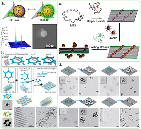
Figure 15. Examples of different DNA origami applications. (a) Top: schematic view of the AuNP-DNA origami nanolens. Three differently sized nanoparticles (20 nm—10 nm—60 nm) are arranged on the Rothemund triangle. Lower left: an FDTD simulation of the lens, showing highest enhancement between the nanoparticles. Lower Right: SEM image of a single Au nanolens on a silicon surface [117]. (b) Assembling AuNP tagged hexagon shaped DNA origami into larger AuNP superlattices. Depending on the size of the arm (connector) of the hexagon (1 × 4 Helices, 2 × 4 Helices or 4 × 2 Helices), the hexagons would assemble into either tubes or sheet/lattices with varying size. In the case of the 1 × 4 connector design, the end result was typically a narrow tube [30]. (c) Schematic view of a roll-up plasmonic chiral nanostructure. Rectangular DNA origami is designed to contain extensions (red and blue) for AuNPs (10 nm) attachment. The two edges of the DNA origami (green) are modified to include sequences that are complementary to the folding strand that can bridge the edges together [122]. (d) Magnetic AuNP-DNA assemblies. The hexagon shaped DNA origami design based on the same DNA origami as in figure (b), but instead of the symmetric binding specific connector strands were added after binding AuNPs to the monomeric hexagons to initiate the assembly into bicyclic, tricyclic, tetracyclic or 1D chain (see TEM images). For the bicyclic, tricyclic and tetramcyclic, the scale bars in the larger TEM images are 200 nm and 50 nm in the insets. For 1D chain, the corresponding scale bars are 500 nm and 200 nm, respectively [123]. Figures (a)–(c) adapted with permission from [30, 117, 122], copyright 2017, 2016 and 2012, American Chemical Society. Figure (d) reproduced with permission from [123], copyright 2019, Wiley.
Download figure:
Standard image High-resolution imageThe ability of DNA origami to precisely arrange plasmonic nanoparticles and molecules has also been exploited for fluorescence enhancement studies [124]. The precise placement of fluorescent dyes and nanoparticles was used to determine exact rates for excitation and radiative decay of molecules close to nanoparticles [125], and to achieve up to 5000× fluorescence enhancement and single-molecule detection at high background concentration of fluorophores [126]. Furthermore, a natural light-harvesting complex was positioned into a DNA origami based dimeric optical antenna to detect its fluorescence with an enhancement of 500-fold [127].
The aforementioned studies have focused on creating single-DNA origami-level plasmonic structures. However, as was discussed in section 2.2, upscaling and building hierarchical assemblies has become an increasingly attractive option. One example of this is hierarchical structures made from hexagon tile shaped DNA origamis connected to each other via DNA hybridization (figure 15(b)) [30]. Depending on the bending, rigidity and intrinsic twisting of the hexagon tile DNA origami and the connector arm design (4 helix vs 8 helix interface), the hexagon adopted either planar, 2D sheet or tubular conformation. One of the more crucial parameters was the connector design, where introduction of a specific gap in the connector design resulted in change from tubular design to open array. This was attributed to increased flexibility in the design that favours the flat sheet design. Furthermore, 30 nm AuNPs were attached to the centres of the hexagons or to the outer pockets, resulting in either regularly spaced 2D AuNP arrays or 3D AuNP tubes.
A lot of progress has been made recently in the construction and application of DNA origami based chiral plasmonic nanostructures, where the shape of the DNA origami and positioning of nanoparticles can be used to produce assemblies that exhibit chiral response. Different examples of this were demonstrated by Kuzyk et al [128, 129] and Shen et al [122]. In one of their articles, a rectangular DNA origami was designed to include capture extensions for two nanorods coated with complementary DNA strands for either left- or righthanded configuration [128]. These structures exhibited strong, bisignate CD response around 730 nm and weaker around 520 nm. In a following article, Kuzyk et al created different kind of left- and right-handed nanoparticle 3D helices using 24-helix bundle DNA origami [129]: 9 attachment sites were located along the tube axis to bind 10 nm AuNPs to produce either left- or righthanded chiral response with bisignate peak at 524 nm, depending on the chosen helicity. By increasing the particle size to 16 nm, the chiral response was stronger and shifted to slightly longer wavelengths (the peak at 545 nm).
In contrast, the approach by Shen et al incorporates dynamic elements into the final assembly of the chiral structure [122]. In their work, a rectangular DNA origami patterned by two lines of AuNPs (10 and 13 nm) was rolled into a 3D tube by introduction of folding strands that bind two opposite sides of the DNA origami together (figure 15(c)). The resulting 3D AuNP helix had a chiral bisignate peak at 525 nm. The authors continued the research further [130] by positioning four 20 nm AuNPs on a rectangular DNA origami in left- and right-handed asymmetric tetrahedron formation. Strong plasmonic coupling between the particles combined with the handedness of the formation gives rise to strong bisignate CD response around 520 nm.
Besides controlling electric fields, magnetic fields can be also manipulated using DNA origamis and metallic nanoparticles. One motivation for this is that while the transfer of an electric field between two particles suffers from significant energy losses, magnetic field-based systems have much higher coupling efficiency. Here, the key point is the hierarchical assembly that produces the desired optical properties. Under illumination, metallic, ring-like structures can produce a circulating displacement current that creates a magnetic field. This idea was utilized by arranging AuNPs into rings using a hexagon shaped DNA origami as a platform [123]. The DNA origami was used to capture six AuNPs (10 nm) in hexamer configuration and further several DNA origamis could be linked together to form either bicyclic, tricyclic, tetracyclic or 1D chain networks of nanoparticle rings (figure 15(d)). The AuNP-DNA origami assembly was deposited on a copper grid and the particles were grown larger using a silver enhancement kit until the particles were 45–50 nm in diameter, thus completing the metallic circle. It was shown that the single metallic ring alone displayed a strong dark field scattering peak at 500 nm and 570 nm, corresponding to electric and magnetic dipole resonances. The optical characterization and the corresponding simulations of bicyclic, tricyclic, tetracyclic and 1D chain showed different optical response: the bicyclic had antiferromagnetic behaviour (two peaks at 455 nm and 560 nm), whereas both the tricyclic and the tetracyclic compounds showed Fano resonances (a peak at 605 nm and a dip at 575 nm in the tricyclic case). The 1D chain consisting of six rings displayed resonance peaks at 520 nm and 660 nm, corresponding to electric and magnetic surface plasmon polaritons (SPP), respectively.
DNA origami can also be used to arrange plasmonic nanostructures for a subsequent optical modification. As an example, Liu et al [131] demonstrated that a rectangular DNA origami can be used to precisely position two gold nanorods close to each other so that they could be physically welded together using a femtosecond laser. The welding is based on the plasmonic excitation of the nanorods (with the localized surface plasmon resonance at 738 nm) by a matching laser (800 nm), where two closely positioned rods form a strong hotspot that melts the rods together. To achieve this, the rod positioning should be on the order of a few nanometers, which is relatively easily achievable using DNA origamis.
Besides nanoparticles, also fluorescent dyes can be used to enable optical interfacing: it is possible to create complex arrays of dyes on DNA origami with the aim to optimize energy-transfer pathways in between the dyes simply by controlling their positions on the DNA origami and in this way to improve their light-harvesting properties [132–134]. In such artificial light-harvesting structures multiple donor dyes channel the absorbed light energy into a single acceptor dye or even reaction center [135]. By using the same number of donor and acceptor dyes it was demonstrated that the FRET efficiency between donors and acceptors can be increased simply by increasing the size of the dye arrays. It was demonstrated that this design can be used to create ratiometric FRET based pH sensors that are independent of the probe concentration and any instrumental fluctuations [136].
DNA origami can be also combined with nanophotonic systems to alter or enhance the properties of the system. In 2016, Gopinath et al fabricated a nanophotonic hybrid device by precisely positioning dye-modified Rothemund triangles into an electron beam lithography (EBL) patterned photonic crystal cavity on a silicon nitride—silicon substrate [137]. Due to the self-assembly and site-specific functionalization of DNA and the high-precision patterning of EBL, different amounts of dyes can be loaded to the DNA origami and the position of singular or multiple (up to 7) DNA origami within the cavity can be controlled with 20 nm precision, which both influences the enhancement of emission of the cavity.
4. Stability, stabilization and upscaling of DNA origami
4.1. Stability of DNA origami
In any life- or materials science applications, when changing the environment from native to the DNA origami to an arbitrary one, it is paramount to consider the stability and structural integrity of the DNA structure: are the shape and the functionality still retained? One of the key properties for any material is the ability to adapt to new environments. To shed light on the matter, five different chemical and physical parameters are considered in this review (see figure 16): pH, temperature, ionic strength of the buffer, radiation and endonuclease degradation. It should be pointed out, that when discussing about the stability of DNA or its derivatives, we are mainly considering DNA suspended in a liquid medium. However, in certain cases the discussion will be extended to include the dry state, in which case the DNA assemblies are immobilised on a surface and are typically able to retain their shape better than in liquid.

Figure 16. Overview of factors influencing the DNA origami stability. In the center the conditions are outlined, under which DNA origami structures are typically stable (dark grey). Further away from the center (lighter grey), the conditions that lead into partial degradation of DNA origami structures are depicted. The conditions for disintegration or decomposition of the DNA origami are outlined in the outer ring (light grey).
Download figure:
Standard image High-resolution image
Before examining these different aspects, it should be also noted that there are two main factors that contribute to the overall stability of DNA double helix [138]: the hydrogen bonds between two complementary nucleotides and the base-stacking interactions (see also sections 2.1 and 2.2 for a discussion on their role in creating higher order DNA nanostructures). These two interactions are overcoming the repulsion of the negatively charged backbones and thus stabilize the DNA origami. As already mentioned, in neutral conditions, binding of two ssDNAs and the formation of the double helix structure can be understood via the Watson-Crick base pairing model. Any condition, that would disrupt these interactions or break the base pairing, will lead to denaturation and degradation of the DNA origami. For example, at low pH cytosine gets protonated and DNA can adopt non-Watson–Crick base pairing, i.e. Hoogsteen base pairing [139]. As a consequence, three separate strands, instead of two strands, can combine together and form a triple helical structure with an altered helical twist, which might lead to deformation, aggregation or disintegration of the DNA origami. Additionally, low pH can lead to hydrolysis of the phosphodiester bonds in the DNA backbone. But, as was discussed in chapter 3, in certain cases, these kind of 'unwanted' interactions can be used to one's benefit.
As DNA origami consists of the scaffold and a set of oligonucleotides with varying lengths, the DNA origami design, i.e. the hybridization lengths and the placement of crossovers, plays a crucial role in the formation and robustness of the DNA origami. Unfortunately, this also means that one good set of experimental parameters for one DNA origami might not work for a different DNA origami. Indeed, the literature is filled with a plethora of different stability studies using different DNA origamis with varying results [140, 141]. Here, we try to shed light on the matter by discussing case by case the set of conditions in which the DNA origami is still stable and intact, but one should bear in mind that the findings cannot be necessarily applied universally. Also, when comparing results between liquid suspended and surface-bound and immersed samples, the influence of the substrate cannot be entirely neglected and one should expect discrepancies between the two states even when using the same DNA origami design. However, we believe that the discussed findings can give the reader a sufficient overview over the DNA origami stability and, for the reader's convenience, we devised a stability map of DNA origami based on the current understanding (see figure 16).
In the case of temperature stability, it is important to note two key factors: the folding and the melting temperatures. As the name suggests, these are the temperatures where the oligos and scaffold bind together in unison to form the DNA origami or where they are dissociated, respectively. The thermal stability of different, well-established DNA origami shapes has been investigated quite extensively, and the most commonly studied structures are the triangular and rectangular Rothemund origamis [7], differently sized helical bundles [142], block DNA origamis [11] and gear-like DNA origami [143].
In the case of rectangular DNA origami, Song et al [144] showed that the surface-bound and immersed DNA origami remained intact while the surrounding temperature was kept below 50 °C. Upon heating to 55 °C, dissociation of DNA oligos was observed and further heating resulted in higher loss of oligos and a more significant deformation of DNA origami until eventually the DNA origami disintegrated at 75 °C. Usually the dissociation process initiated from the edges of the rectangle. In the same vein, it was reported that the thermal stability and integrity of the DNA origamis depend strongly on the position and the length of the staple strands [145]. In this study, FRET pairs were used to detect the hybridization and unfolding of individual strands in various positions on rectangular and 3D block DNA origamis. It was found out that the melting and folding temperatures of staple strands around the edges and close to the seam had significantly lower melting temperatures compared to the so called bulk strands. Overall, the disintegration of rectangular DNA origami typically started around 57 °C and the unfolding was completed at 58 °C. For a 3D DNA origami block, the same temperatures were 54.6 °C–60.4 °C, respectively [145].
The Liedl group [143] investigated the folding and unfolding process of plate-, brick- and gear-like DNA origamis. They have reported that depending on the composition of the used oligos, i.e. the shape of the DNA origami, the temperatures for the co-operative DNA origami folding were occurring between 55 °C and 49 °C (plate highest, gear lowest) and the unfolding happened at slightly higher temperatures, between 67 °C and 60 °C (plate highest, gear lowest). By incubating the strands of the specific DNA origami designs in their respective folding temperatures, different DNA origamis could be produced in 15–40 min time scale. In addition, they showed that increasing the average length of oligos increased the folding temperature while the unfolding temperature remained largely the same, and introduction of internal stresses like bending decreased the folding temperature or, in the worst case, completely blocked the folding. Similarly, Castro et al [10] evaluated the structural stability of differently sized helical bundles (18HB, 42HB and 35HB). They observed that all of the bundles were intact at 37 °C for longer periods (7 d), but upon heating to 55 °C the DNA origami structures were damaged at the end interfaces of the bundles while the body of the bundle remained largely intact. Further heating to 65 °C resulted in a complete loss of structure.
In addition to studies in liquid, Pillers and Lieberman [146] investigated thermal stability of dried rectangular DNA origami on a mica surface. The authors showed that the DNA origami could withstand a temperature of 150 °C up to 45 min without any significant alteration of the physical size or the fine features of the structure. Incubating the DNA origami in 250 °C for 10 min resulted in significant physical alterations such as decrease of the height to half from the original and loss of any fine features. On the same note, in another study [147] the shape of surface deposited triangular DNA origami were retained until 300 °C under both air and argon, but the height of the structure decreased after 200 °C.
Besides just the direct heating, the co-operative effect of heating and presence of different chemical agents on the melting temperature of DNA origamis has garnered interest. Ramaknishnan et al [148] reported effects of the presence of the chaotropic and denaturing agents urea and guanidinium chloride (GdmCl) on the integrity of triangular DNA origami at various temperatures. During the experiments, DNA origamis were incubated in different urea or GdmCl concentrations and at different temperatures (23 °C, 30 °C, 37 °C, 42 °C). It was observed that at RT the triangles were stable and structurally intact even in 6 M concentration of both urea and GdmCl. If increasing the temperature, in the case of urea, the triangles were intact at 42 °C up to 4 M concentration. In the case of GdmCl, no significant structural deformations were observed in 1 M and 2 M concentration up to 42 °C, but partial malformations of the triangles were observed to start at 37 °C and 4 M concentration or at 30 °C and 6 M. Any further increase in either the temperature or the concentration of GdmCl would lead into further degradation of the DNA origami. Interestingly, the first observed malformation was the cut or loss of the trapezoids that hold the sides of the triangle together. This would suggest that the single, exposed ssDNA or dsDNA portions of the DNA origami are the most vulnerable position in the DNA origami. Also, the authors measured the melting temperatures of the triangles in different urea and GdmCl concentration. Interestingly, the melting temperature was found out not to reflect fully the disintegration of the triangles observed in AFM imaging, suggesting that one cannot rely entirely on the melting temperature when estimating the integrity of DNA origami. Lastly, increasing the incubation time up to 24 h revealed that there were no further degradations in the urea samples after 1 h but in the case of GdmCl decrease in the amount of intact structures was observed until 24 h.
Related to the previous topic, the lowering of melting temperature by different agents can be utilized in one's advantage. Jungmann et al [149] folded the rectangular DNA origami and the 6HB by introducing formamide and urea during the folding process. In these experiments, formamide concentration was reduced in a stepwise manner from 85% to less than 1% in the case of the Rothemund rectangle and from 85% to 11% in the case of 6HB. Since the introduction of denaturing agents lowers the melting temperature of DNA oligos, the subsequent decrease in the concentration of denaturing agents will increase the melting temperature and thus stabilize the hybridization, which essentially simulates the temperature ramping process. Rectangular DNA origamis required overnight folding while the 6HB could be assembled just over 2 h. The urea folding followed a similar pattern. The advantage of this methods is that one could incorporate temperature-sensitive elements to the DNA origami structure during the folding process or proteins could be folded at the same time as the DNA origamis.
For any biological application, the resistance against endonuclease degradation is quite vital. Besides the temperature studies, Castro et al characterized the structural stability of abovementioned DNA origami bundles in cell culture medium (0.5× Dulbecco's modified Eagle medium), Tris buffer containing either different crowding agent (BSA, Dextran) and sodium chloride, magnesium chloride and a low pH buffer [10]. TEM imaging and gel electrophoresis revealed no significant changes in the structure of all DNA origamis in all of the buffer conditions. Finally, the stability against different enzymes like DNase I, T7 endonuclease I, T7 exonuclease, E. coli nuclease, lambda exonuclease and MseI restriction endonuclease were tested for all of the bundles. All other enzymes except DNase I and T7 endonuclease I did not have any significant impact on the DNA origami structures. In another study, the stability of triangular, rectangular and 6HB DNA origamis was tested in cellular environment [150]. Based on gel electrophoresis and AFM and TEM imaging, all of the aforementioned DNA origamis could survive up to 12 h in cell lysate buffer (metaplastic human esophageal epithelial cell line) at RT and 4 °C without any significant degradation. In comparison, M13mp18 scaffold and λ-DNA (47 kbp) were subjected to the same conditions, which resulted in significant alteration of both species suggesting that the compact structure of the DNA origami hinders the digestion process of the enzymes. This topic was further explored by Stopar et al [151], who demonstrated that 11 specific restriction enzymes could be used to site-selectively cleave the triangular and rectangular DNA origamis. Here, the nucleolytic reactivity was controlled by introducing structural defects (base mismatches) to the DNA origami design.
As discussed in the introduction section, the buffer conditions are quite crucial for the folding and long term integrity of DNA origami, where the pH and the ionic strength play a crucial role. To shed light on the matter, Kim et al [147] studied robustness of the surface deposited Rothemund triangle at various buffer conditions. The stability of substrate bound DNA origami was tested in hexane, ethanol, toluene, deionized water, NaCl solutions and at various pH conditions. The DNA origamis showed no significant degradation in hexane, toluene or ethanol after 24 h immersion: height variations were observed, but the shape and the surface density of DNA origamis stayed the same. Immersion in deionized water resulted mainly in detachment of DNA origamis from the silicon surface and some defective structures were observed after 5 min incubation. Incubating the DNA origamis in 0.01 M, 0.05 M and 0.2 M sodium chloride for 10 s resulted in detachment of DNA origami from the surface and the remaining DNA origamis appeared to be rougher, possibly indicating that sodium is accumulating in the DNA origami structures. The pH stability was tested by immersing the surface bound DNA origamis in pH 2–4 and pH 10–12 solutions. While the triangles were very unstable and disintegrated quickly in acidic conditions, the overall shape and size was maintained until pH 11. At pH 12, the overall shape was maintained although the fine structure of the triangles became blurred. Continuing on the same subject, Wang et al [152] showed that a bundle DNA origami could withstand 10% ethanol (v/v), 2-methyl-1,3-propanediol and glycerol addition, Tris, HEPES, PEPES and MES buffers, pH levels between 5–10, 30% (w/v) PEG precipitation and sodium concentrations between 0.2 M and 3 M. However, cations such as potassium (K+), calcium (Ca2+) and ammonium (NH4+) at a concentration of 200 mM and sodium at 4 M resulted in disintegration of the DNA origami. Also, four different protein crystallization buffers were tested: Lysozyme, Thaumatin, Human Serum Albumin and Catalase. The DNA origamis were only stable in the catalase buffer after the buffer exchange. In a similar study, as an indirect proof of stability, it was demonstrated that different DNA origami bundles can be folded in presence of sodium [153]. They have shown that 0.2–1.4 M of sodium chloride is required to fold 6, 8, 10, 12, 18, 24 and 42 helix bundles and that these bundles are stable in that solution.
To complement the before mentioned studies, Kielar et al [154] tested the conditions where the Rothemund triangle, 24HB and 6HB remained structurally intact after buffer exchange by spin filtering twice. Nine different buffer exchanges were tested: to pure water, TAE, Tris, Na2HPO4, Na2HPO4 and 100 mM NaCl, Na2HPO4 and 200 mM NaCl, K2HPO4, K2HPO4 with 100 mM KCl and K2HPO4 with 200 mM KCl. The internal structure of the triangles remained largely intact in the case of pure water, Tris, Na2HPO4 with 200 mM NaCl, K2HPO4 with 100 mM KCl and K2HPO4 with 200 mM KCl, while there was significant structural degradation observed in the other cases. This is in agreement with the abovementioned results. The 24HB remained intact only in Tris buffer. The 6HB showed no visible damage in all of the cases. These results indicate that firstly the DNA origami design has a huge influence on the stability of the structure and secondly stabilizing cations like sodium can be introduced to buffers to increase the stability of the DNA origami. Also, the long term stability of each DNA origami in the positively tested buffers were studied, which showed that DNA origamis were stable even after two months of storage at 4 °C.
The last parameter discussed here is the stability of DNA origami under illumination with electromagnetic radiation. Here we consider two regions: high energy (below 350 nm, UV) and low energy (above 350 nm, visible + IR) photons. In the low energy region the DNA origamis do not interact directly with the electromagnetic radiation. In fact, many optical applications based on DNA origami operate in this region. For example, Liu et al [155, 156] successfully utilized triangular and rectangular DNA origamis as platforms to assemble quantum dots that operate from 360 nm up to 1300 nm, Kuzyk et al showed that 24HB DNA origami could be used as scaffold to assemble chiral plasmonic assemblies that operate in the visible region [83, 87] and Willner et al demonstrated photo switchable DNA nanoscissors [157]. Even indirect effects such as the local heating from plasmonic nanoparticles do not have any significant influence on the integrity of the DNA origami structures. It should be noted that photodegradation is a time dependent phenomenon, and the listed studies usually concern relatively short time scales.
Although the discussion revolves around the energy of the radiation, in truth it is the dose that dictates the damage to DNA structures in the high energy region. This becomes apparent in several publications by Vogel et al [158, 159], Chen et al [160] and Gerling et al [161], where even under high energy UV illumination but with low dose DNA origamis can preserve its overall shape. Vogel et al [158] studied the DNA single strand breaking under vacuum (V) UV irradiation (138 nm and 190 nm) for two different DNA sequences. In the experiments, triangular DNA origamis with protruding ssDNAs at specific positions and modified with biotin at the end were first deposited on the surface and then irradiated by VUV radiation. Although not analysed in the article, the AFM images showed that the triangular DNA origami was intact after VUV exposure and washing steps, indicating that the double stranded DNAs were not heavily affected by the exposure. Also, the effect of substrate should not be excluded in the high energy region due to generation of secondary electrons. In a later article Vogel et al [159] could show that silicon surface produced about factor of 2–3 higher bond breakage than in the case of calcium fluoride due to the generation of reactive secondary electrons.
Chen et al [160] studied the UV induced flattening or straightening of two different DNA origamis (rectangular and ribbon). Usually DNA origamis contain internal stresses that cause the structure to twist and bend. This twist and bend can be relieved by UV induced minor lesions to DNA origami, so that the DNA origami can reorient itself. Three different UV wavelengths (366 nm or UVA, 312 nm or UVB and 254 nm or UVC) were investigated. Under moderate exposure to UVB or UVC irradiation, the DNA origami structures were flattened without significant structural damage, but under UVA illumination the conformations of DNA origamis were unaltered suggesting that they are unaffected by this wavelength. Increasing the dose of UVB and UVC illumination resulted in steady disintegration of the DNA origami, but UVA had no effect even at high doses.
Since the DNA origami can withstand exposure to UVA irradiation, Zhuang et al [162] studied the capability of triangular DNA origami to function as a photosensitizer carrier in this region. Here we will shortly discuss the effect of intercalation of photosensitizers on the photostability of a DNA origami structure. 3,6-bis(2-(1-methylpyridinium) ethynyl)-9-pentylcarbazole diiodide (BMEPC) was loaded into Rothemund triangle by incubating the DNA origami in BMEPC solution for 12 h at RT. AFM images before and after incubation show that the DNA origami structure was swollen up after incubation but the overall shape was retained. After loading, DNA origami was illuminated using 365 nm UV light resulting in partially malformed DNA origamis, although this seemed to be dependent on the amount of loaded BMEPC per DNA origami: at a DNA origami to BMEPC ratio of 1:15 000 and after 1500 s UV irradiation of the intact DNA origami band in gel electrophoresis was visibly weaker than the control band. Also, the plain DNA origami did not show any sign of degradation under the same UV irradiation in the gel electrophoresis. In addition, the degradation was shown to be time dependent, meaning the BMEPC loaded DNA origamis were degraded significantly after 4500 s exposure.
4.2. Stabilization and protection of DNA origami
The stability of DNA origami described above concerns the non-modified DNA nanostructures. In the meantime, several protection strategies have been reported to stabilize DNA origami in various chemical environments and biological media. Some of these strategies have been touched upon in the preceding sections already, but will be summarized here again.
So far we have established, that different DNA origami structures are usually stable in solution until about 50 °C, at higher temperatures between 55 °C and 67 °C they start suffering structural damage and ultimately disintegrate. Many researchers have sought to increase these temperatures by various means. An interesting and simple stabilization strategy is the irradiation with UV radiation, which can not only lead to strand breakage, but also to stabilizing cross links. The Dietz group [161] investigated the effects of UV irradiation on two brick-like DNA origamis that had been modified to include thymidines at strand termini and crossover positions. The re-enforcement of DNA origami arises from the fact that these thymidines can covalently crosslink under UV irradiation, thus strengthening the whole DNA origami. Modified brick-like DNA origamis were illuminated for 30 min with 310 nm wavelength illumination. Afterwards, the melting point was determined in the gel electrophoresis and the integrity was checked in TEM. Irradiated samples were stable up to 90 °C heating, while non-irradiated ones break after 50 °C or 45 °C, which is a quite significant improvement. Also, the irradiated samples were stable in sodium chloride buffers (up to 300 mM) and in pure water. However, as it was pointed out in the article, a long term UV exposure led to damaged DNA origami structures. In another example, it has been demonstrated [163] that photo-cross-linking materials such as 8-methoxypsoralen (8-MOP) can be used to enhance the thermal stability of DNA origami: upon incubation DNA origami with 8-MOP and subsequent 1 h UV-radiation with 365 nm laser, the melting temperature of rectangular DNA origami could be increased from 58 °C to near 90 °C. A similar, but more specific and reversible photochemical cross-linking can be achieved using 3-cyanovinylcarbazol moieties [33, 164].
Chemical protection of DNA origami can be achieved e.g. by coating the DNA origami with cationic PEG-poly-lysine block copolymers resulting in DNA origami polyplex micelles [165]. The coverage of the DNA origami is purely electrostatic and hence reversible by using polyanionic dextran sulfate. The block copolymers protect the DNA origami against decomposition by nucleases and low-salt conditions. A similar strategy uses DNA-lipid conjugates that are attached to DNA nanostructures in a surfactant solution forming micelles around the DNA nanostructures [97]. Subsequently, liposomes are added and the surfactant is selectively removed by dialysis resulting in a fused lipid bilayer around the DNA nanostructure mimicking a virus capsid shell, which protects it from nuclease digestion and prevents immune reactions. Virus capsid proteins can also cover DNA origami electrostatically to increase the transfection efficiency into cells [96]. In an alternative approach atom transfer radical polymerization was used to protect a rectangular DNA origami rolled into a tube [106]. The authors also demonstrated that the formed polymer tube could protect a G4/hemin complex inside the tube and that the complex could still be used to initiate dopamine polymerization. Protection of DNA origami can also be achieved by enzymatic phosphorylation and ligation of staple strands [166], which proved to be especially effective in conjunction with a redesign of staple strand lengths.
4.3. Scaling-up DNA origami synthesis
In order to use DNA origami as multifunctional materials it is likely that larger amounts of material are required, for which it is critical to reduce the costs of their production. Recently, significant advances have been made to reduce the costs of DNA origami production and to up-scale its synthesis using biotechnology. In 2015, it was demonstrated that the long scaffold DNA M13mp18 can be obtained in the gram scale per liter-reaction-volume from bacteriophages with fast-growing E. coli as host cells by using high-cell-density fermentation in a stirred-tank bioreactor [167]. Later, the same method was extended to produce also the shorter staple strands with specific sequences using a phagemid system with enzymatic digestion [168]. In this way the production costs of the staple strands can be reduced by more than two orders of magnitude while large-scale mass production of DNA origami in the gram scale is possible [168]. A similar approach to produce kilobase single-stranded DNA at low cost was demonstrated by Shepherd et al, who used this DNA to create wireframe DNA origami objects [169].
5. DNA origami design tools
From the early humble structures such as Holliday junctions to modern day 3D DNA origami gears, as the demand has risen over the years to fold evermore intricate DNA structures, so have the available tools developed from pen and paper to computational methods. Among these computational methods are toolkits such as caDNAno [170], Tiamat [171, 172], DNA meshing (vHelix) [173], oxDNA [174, 175], Brownian Dynamics (BD) model [176, 177] and CANDO [178] that help to standardize designing and folding of arbitrarily shaped DNA objects paving the way for future applications. While providing the most accurate tool to build models, an all-atom Molecular Dynamics (MD) simulation is usually not accessible for regular users due to high computational power requirements, which we are therefore excluding from the present discussion. However, authors like Yoo and Aksimentiev have used MD simulations to evaluate the local structure of different DNA origamis in aqueous conditions and assess properties like stability, amount of broken base pairs and structural deformations in finer details [179]. Also should be noted that the caDNAno, DNA meshing, BD model, oxDNA and CANDO are based on the classical Watson-Crick model where the DNA helix adopts the B-DNA form and other forms of DNA are not considered in this article. To evaluate the different techniques, their strengths and weaknesses, we compiled a list of features of each method in table 1.
Table 1. Overview of different aspects of DNA origami simulation and design tools.
| Design tools | Structure | Input | Output | Lattice structures | Export 3D model | Positive aspects | Constrains/ Drawbacks |
|---|---|---|---|---|---|---|---|
| SARSE | 2D | Shape | Staple sequence | Honey Comb | No | Shape imported directly from images | Only 2D DNA origami |
| caDNAno | 3D | Shape | Staple sequence | Honey Comb and Square | Yes | Versatile manipulation possibilities | Helices constrained in one specific direction. |
| Tiamat | 3D | Shape | Staple sequence | Polygonal Mesh | Yes | Suitable of large and complex structures | Limited to N-way junctions |
| vHelix | 3D | Shape | Staple sequence | Polygonal Mesh | Yes | Arbitrary shape | Hollow and flexible structures |
| Deadalus | 3D | Shape | Staple sequence | Polygonal Mesh | Yes | Arbitrary shape | Hollow and flexible structures |
| Scaffold Smith | Scaffold | User-defined sequence motifs and strings | Scaffold sequence | — | — | introduction of functional motifs, modification-free UV-CLa, tuning of assembly-T | |
| Simulation tools | Model | Resolution | Simulated Processes | Included features | Sim. Buf. conditions | Excluded features | Modelled features |
| CANDO | Isotropic, elastic rods | Helices | Structural, Mechanical | S&Scoa and backbone nicks | None | SSbpa, EVa, M&Ma | Global Origami Twist |
| BD model | Elastic beam (mechanical) or bead (hydro-dynamic) | Nucleotides | Structural, Mechanical | S&Scoa, CBa | MgCl2, 12.5 mM | SSbpa, EVa and vdW-Ea | |
| oxDNA1/ oxDNA2 | Strands as strings of ridig-body- nucleotides | Nucleotides | Structural, Mechanical, Thermodynamic | Basepair, S-Ba, BCa, Staa, SSa, EVa and vdW-Ea | NACl above 0.1 M | Non-Cbpa | Helix pitch, M&Ma, Basepair radius and twist |
| nGC-dsDNA | Nucleotides as beads and interactions as springs | Nucleotides | Structural, Mechanical | Basepair, BCa, Staa, SSa, EVa, CBa | NaCl from 1 to 500 mM | Non-Cbpa, CBa | Only dsNDA |
aCL = cross-linking, S&Sco = staple and scaffold crossover, EV = excluded volume, vdW-E = van der Waals and electrostatic interaction between helices, SS = salt screening, S-B = sugar backbone, BC = backbone chain, Sta = stacking, CB = chain bending, SSbp = sequence specific basepairing, M&M = major and minor grooves, Non-Cbp = non-complementary basepair interaction.
After Rothemund published his famous article in 2006 [7], Andersen et al [180] were among the first to introduce computational methods to help to design arbitrary DNA origami shapes. In their article, the authors utilized a graphical interface (SARSE) to design arbitrarily shaped DNA origamis. Briefly, the designing is done by uploading the desired shape as a bitmap into the software and routing the scaffold strand throughout the whole image. Finally, the staple strands and their sequences are generated, which can be submitted by the end user to a DNA oligonucleotide manufacturer for production. The power of the toolkit was demonstrated by folding a 2D dolphin-shaped DNA origami [180].
A significant step in the DNA origami development was the introduction of caDNAno [13], which is widely used for designing DNA origamis. A typical design process follows the formula of shape selection, designing scaffold crossovers, generation of staples, a rational partitioning of staples into smaller, preferentially 18–49 nt long segments and finally generating the staple sequences. DNA origami can be designed in either honey comb or square lattice, which will influence the packing density, maximum size and robustness of the DNA origami. A drawback of caDNAno is that the designs are inherently solid, bulky objects requiring a lot of material. However, this issue has been address by third party software [181] that allows caDNAno to be used to design e.g. wireframe structures like trusses. Compared to SARSE, new features were included such as automatic staple generation and highlighting the natural crossover points for both scaffold and staples, which vastly cuts down time and helps to avoid internal stresses in the DNA origami design. Also, combined with software like Autodesk Maya (Autodesk Inc., USA), caDNAno can be used to produce 3D models of the DNA origami, which can be uploaded to 3D printers to produce real life models of the DNA origami. In 2019, a tool called 'scaffold smith' was introduced to allow the construction of design-specific scaffolds with different sizes ranging from 1024 bases up to fully orthogonal scaffolds that allow for multiscaffold assembly of DNA origami with up to 38.000 base pairs [182]. The design of scaffolds allows to introduce e.g. functional motifs, to tune the assembly temperature, and to do one-pot assemblies with multiple scaffolds. Furthermore, the scaffold strings can be designed such that modification-free UV cross-linking can be done.
Tiamat offers a flexible route to design arbitrarily shaped DNA structures with the caveat that the crossovers between helices are limited to N-way junctions. A graphical interface is used to draw the desired shape and the algorithm defines the necessary strands and the sequences based on several user defined constrains: there exists a certain minimum percentage for the number of guanines and cytosines, the same base cannot appear too many times in a row (e.g. TTTTTT) and any subsequences with a user defined length can only appear once in the structures. The last case is set to prevent formation of unwanted secondary structures due to too similar subsequences in different strands or even within one strand alone. Due to flexibility of the design, Tiamat is well suited to design complex and larger DNA structures.
Another unique DNA design method is based on polyhedral meshing using vHelix software. In polyhedral meshing the designed objects are hollow and the surface is divided into multiple triangles [9]. Each side of the triangle corresponds to one DNA helix and, similar to the DNA origami, a scaffold strand runs through the whole structure. The system is constrained so that the scaffold does not crossover itself at the vertices and vertex junctions should be planar. The final output is the set of necessary staple strand sequences. As an example, nanoscale bunny and soda bottle shaped DNA structures have been generated successfully, which is more difficult to fabricate using above-listed DNA origami approaches, at least in the level of detail shown in the TEM images [9]. However, although polyhedral meshing produces quite intricate shapes, they are inherently flexible due to their hollow nature, which might not be favorable for certain applications, whereas e.g. caDNAno designed DNA origamis are usually quite robust albeit rather bulky structures.
Similar to vHelix, Deadalus uses also similar polyhedral meshing to construct any arbitrary shape [183]. However, in Deadalus, each side consists of double crossovers (DX) instead of an individual helix, scaffold crossovers are used in the vertexes, each helix comprises scaffold strand and staple strand and the used scaffold can be any natural or synthetic ssDNA of arbitrary length. Also, the edge lengths are set as multiples of 10.5 bp (B-DNA helicity) to avoid any over- or underwinding of DNA helices. The used algorithm takes the user-generated shape as an input and calculates the necessary ssDNA scaffold and staple sequences and simulates the resulting atomistic model of the DNA origami. Veneziano et al [183] demonstrated flexibility and power of the method by folding differently shaped and sized tetrahedrons, cubes and bipyramids. By comparing the AFM and cryoTEM images of the folded structures to the atomistic model, the resulting structures were found to be in good agreement with the predicted model.
Since softwares such as caDNAno, Tiamat and vHelix predict only theoretical shape but not the morphology in solution, oxDNA, BD and CANDO toolkits have been developed to simulate the more realistic shape of DNA nanostructures. These early glimpses into possible morphologies of DNA origami can give insight to the stability and shape deformation. This is often preferable to laborious folding, probing by gel electrophoresis and imaging all the possible permutations of staple strands to figure out any design flaws. It should be kept in mind though that these programs simplify or often even neglect certain interactions between DNA strands to minimize required computing power. For this reason, we compiled a list of positive aspects and constrains to the table 1 for each simulation technique. All the tools are able to simulate DNA origami structures and all of them provide the 3D structural model of the DNA origami.
In CANDO, the helices are modelled as isotropic elastic rods that are constrained by the crossover points. Single stranded DNA connections between double helical domains are modelled as non-linear springs and backbone crossovers are modelled as zero-dimensional, rigid links. The predicted model is computed from initial, deformed structures by first aligning the strand crossover positions based on the B-DNA model, then applying crossover constrains and lastly iteratively calculating the shape that has the minimum mechanical free energy using finite element (FE) simulations. An early example of how CANDO simulation can be applied to predict the folded structures was presented by the groups of Dietz and Bathe, who successfully predicted the shapes of several unique DNA origamis such as S-shape and robot-like objects in CANDO when compared to equivalent TEM images [178]. However, CANDO does not provide information about the sequence specific base pair interactions and includes twisting in the global DNA origami level but not on the individual nucleotide level. It also neglects certain features like excluded volume interaction, i.e. the constrain that the volume of two strands cannot cross each other, and major and minor grooves, that are important for certain DNA origami designs.
The simplification in CANDO can help designing standard DNA origami structures with sufficient accuracy. However, for more complex designs, a tool such as oxDNA [174, 175] is required. Here, the interactions such as the excluded volume, stacking (π–π interactions), salt screening and the nearest neighbor interactions are included. This results in finer details such as DNA strand hybridization, basepair bond breaking and determination of melting temperature of short DNA oligomers. For example, Snodin et al [184] demonstrated that thermal fluctuation of rectangular DNA origami can be captured using oxDNA and Schreck et al [185] simulated the thermal fluctuation of a 3-arm tile based DNA origami nanoprism and could successfully reproduce the experimentally observed 3D structure of the DNA origami.
BD modelling adds a dimension to the simulation by using two different models, structural model and hydrodynamic model, to simulate the mechanical motion of DNA origami in liquid environment. The helices and crossovers are approximated as beams and divided into several nodes and worm-like chains. This layer-modelling allows simulations up to microsecond scale for complex 3D DNA origami structures to be possible without need for a supercomputer. BD model was used by Sedeh et al [176], who simulated the thermal fluctuation and ring-breathing of nine-layer ring DNA origami up to the μs scale. However, as the authors pointed out, the BD model excludes interactions such as van-der-Waals and electrostatic interactions and assumes high crossover density as found in most of the DNA origamis, and therefore it should be used in DNA origami simulations. Another MD model (new Course-Grain double stranded DNA model, nCG-dsDNA) to simulate only dsDNA was developed by Yagyu et al [177]. In this model, each individual nucleotide is replaced by one unique bead and the considered interactions are basepair, hydrogen bonding, stacking, backbone connection, excluded volume and chain bending. The authors simulated the mechanical properties of dsDNA like the persistence length, which correlated with the actual B-DNA helix, but in much shorter time than in oxDNA. Possibly in the future, this model could be utilized to simulate the 3D structure of DNA origami.
In summary, there exist currently several different design and simulation tools for DNA origami. The caDNAno, Tiamat, vHelix and Deadalus can be utilized to design almost any arbitrary nanoscale object. Molecular dynamics and oxDNA model are more rigorous in depicting the actual model and calculating mechanical and thermodynamical properties of DNA origami, while CANDO is more user-friendly, but provides still a fairly accurate 3D model. However, all the listed methods are still restricted to certain frameworks and modelling specific interactions like in a DNA triplex (H-DNA), or incorporating biomolecules into the DNA design is currently not implemented into any of the methods. One crucial future aspect would be to combine design and simulation tools to optimize the DNA origami structure for user-defined applications. Currently, since designers of DNA origami do not usually have access or capability to simulate their DNA origami designs in finer details, the typical optimization process requires experimental characterization methods like AFM or TEM to evaluate the correct folding, which in the worst case might lead to ordering several sets of staple strands and waste of time and resources. Recently, to address this issue, Benson et al combined oxDNA simulations and vHelix to create an optimization pipeline, where the best result of the simulations are fed back into vHelix, which provides the next iteration of the design to oxDNA. Based on user defined metrics, the structure with highest score is selected from all candidates for the next iteration and the pipeline runs until the final DNA origami design meets the user-defined criteria [186].
6. Conclusions and outlook
The field of DNA origami nanotechnology is rapidly developing with a huge potential for materials science. The unique features of DNA origami are the precise tunability of their two- and three-dimensional shape and their intermolecular interactions, and the possibility for site-specific chemical functionalizations with nanometer precision. These features allow for example for the creation of dynamic and stimuli-responsive nanoscale and also sophisticated hierarchical microscale structures. They can be used as transporters, can be equipped with nanoparticles and dyes to create innovative optical materials, and can be developed into actuating systems and machines. Introduction of different modelling tools standardizes the designing and creation of DNA origami making it easier to tailor them for specified purposes, so that a wide range of applications of DNA origamis can be envisaged e.g. in medicine, diagnostics, nanofabrication and lithography, molecular electronics and analytical sciences. Besides the development of novel concepts in these fields a critical future challenge lies in the improvement of the stability of DNA origami in different chemical environments and development of more accurate modelling and designing tools to predict the actual, real-life structure of individual origamis and larger, hierarchical assemblies.
Acknowledgments
This work was supported by the European Research Council (ERC; consolidator grant no. 772752).