
Abstract
A quantum computer has the potential to revolutionize multiple industries by enabling a drastic speed-up relative to classical computers for certain quantum algorithms and simulations. Linear optical quantum computing is an approach that uses photons as qubits, which are known for suffering little from decoherence. A source of multiple entangled and indistinguishable photons would be a significant step in the development of an optical quantum computer. Consequently, multiple proposals for the generation of such a stream of photons have recently been put forward. Here we introduce an alternative scheme based on a semiconductor quantum dot (QD) embedded in an optical microcavity in a magnetic field. A single charge carrier trapped in the dot has an associated spin that can be controlled by ultrashort optical pulses. Photons are sequentially generated by resonant scattering from the QD, while the charge spin is used to determine the encoding of the photons into time-bins. In this way a multi-photon entangled state can be gradually built up. With a simple optical pulse sequence we demonstrate a proof of principle experiment of our proposal by showing that the time-bin of a single photon is dependent on the measured state of the trapped charge spin.
Export citation and abstract BibTeX RIS

Original content from this work may be used under the terms of the Creative Commons Attribution 3.0 licence. Any further distribution of this work must maintain attribution to the author(s) and the title of the work, journal citation and DOI.
1. Introduction
One of the primary difficulties with optical approaches to quantum computing comes from the weakness of the photon–photon interaction. Although this weak interaction means that photons are robust against decoherence, it makes performing conditional operations on two photons a challenging endeavour [1, 2]. Linear optical quantum computing, an approach which requires only arrays of phase shifters and beam splitters, was shown to be a scalable by Knill et al [3]. The scheme sidesteps the obstacle of interacting two-photons by using projective measurements to induce effective photon–photon interactions probabilistically via the Hong-Ou-Mandel (HOM) effect. However, it requires an almost infeasible number of optical components [4], in addition to reliable and indistinguishable single photon sources and efficient detectors. There have been proposals that reduce the experimental requirements by generating entangled states as a resource for measurement based quantum computing [5], but these still remain impractical with current technology.
However, in light of the continuing advances in integrated photonic circuits [6–10], it has been suggested that a source of three photon entangled states suitable for stitching together by a HOM based fusion mechanism [11] would finally bring the photonic quantum computer to within reach [12]. The importance of such a source of entangled states has sparked many ideas on how to generate them [13–15]. Of particular interest here is Lindner and Rudolph's proposal for generating a chain of entangled photons from a singly charged quantum dot (QD) [16]. There, the authors suggest the sequential generation of a one dimensional cluster state by synchronizing the repeated pulsed resonant excitation of the QD system with the precession of the trapped spin in a magnetic field.
Lindner and Rudolph's scheme was recently demonstrated experimentally using a dark excition in a QD as the spin instead of a trapped charge [17]. This work serves as motivation to explore the impact of applying recent developments in coherent spin control and cavity QED techniques to the challenge of building a source of photonic states useful for quantum computing applications. With this aim, we introduce a new scheme that encodes the photons in time-bins instead of polarisation. This scheme has the potential to be modified to create a broad set of useful states, as characterized in [18], with linear cluster states being particularly attractive. For this work however, we focus on how we could generate a Greenberger–Horne–Zeilinger (GHZ) state as it is conceptually and experimentally simpler. The necessary modification to the protocol to turn the output into a linear cluster state is outlined in the methods.
2. Proposed scheme
We propose using a QD with a single trapped charge carrier and its corresponding spin. Spins in QDs are especially attractive for the task at hand thanks to their coherence properties [19] and readily available entanglement with photons [20]. This well known platform takes the form of a double lambda system when placed in a large Voigt geometry magnetic field (figure 1), where the four distinct and individually addressable transitions enable fast spin manipulation. In this scheme we use the enhancement of a single vertical transition to allow a cycling transition suitable for spin state readout and entangled photon generation. The proposal for generating time-bin encoded GHZ states, as illustrated in figure 1, is as follows:
- 1.Prepare the trapped hole spin in the
 superposition state by performing spin initialisation and subsequently using an off-resonant pulse to perform a π/2 rotation of the spin.
 - 2.Resonantly drive the cavity enhanced transition with a π-pulse to generate a photon in the first time-bin conditional on the spin being in the state. The resulting state is .
- 3.Flip the spin of the trapped charge to produce the state.
- 4.Resonantly drive the cavity enhanced transition with a π-pulse to generate a photon in the second time-bin conditional on the spin being in the state. The resulting state is .
- 5.Another spin flip yields.
- 6.Repeating steps 2–5 builds up the desired entangled state. After three repetitions the state of the system is
- 7.Finally, a spin readout can be done by applying a π/2 spin rotation and resonantly driving the cavity enhanced transition. This effectively performs a measurement in the basis. Assuming we measure the spin to be in the state, we are left with the photonic state . Rewriting this state using a photon in an odd numbered time-bin to be a logical 1 and a photon in an even numbered time-bin as a logical 0 we have the state - a 3-photon GHZ state.


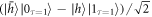


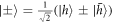


Figure 1. Diagram of the proposed scheme for the sequential generation of time-bin-encoded multi-photon entangled states. The double lambda energy level diagram corresponds to a single hole trapped in a QD in a Voigt magnetic field. The Zeeman-split hole (trion) states are denoted by  and
and  (
( and
and  ). The vertical
  transition is selectively enhanced by an optical cavity and is used to resonantly scatter photons. Each photon (qubit) is spread across two time-bins.
Download figure:
Standard image High-resolution imageThe outlined scheme is conceptually similar to that presented in [16], but poses a series of improvements:
- Time-bin encoding: rather than having the state encoded in the photon polarisation, encoding it in time has two important benefits. First, it allows for polarisation filtering to reject the reflected laser light when performing resonance fluorescence measurements. This is naturally incompatible with polarisation encoding. Second, time-bin-encoded states are well suited for transmission through optical fibre and integrated waveguide technologies as they suffer less from decoherence than polarisation encoding techniques [21, 22].
- Voigt geometry field and spin rotations: the orientation of the magnetic field determines the allowed transitions between the energy levels (see figure 1). At zero magnetic field or in Faraday fields (parallel to sample growth direction) only the vertical transitions are allowed. This configuration is required for the proposal in [16]. The authors suggest using a weak Voigt magnetic field (perpendicular to growth direction) to allow the spin to precess in order to perform the spin rotations needed to generate the cluster state. It is unclear to what extent this Voigt field would remove the Faraday geometry-like selection rules, as in a Voigt field both vertical and diagonal transitions are allowed. This is complicated by the fact that, ideally, one would use a larger magnetic field, as this has been shown to improve the coherence time of the trapped spin [23].In addition, a key advantage of using Voigt magnetic fields is that it allows for high fidelity coherent optical spin rotations, which has not been reproduced in Faraday fields. Of particular interest here are the experiments reported in [24], where a several picosecond circularly polarised laser pulse was used to induce a spin rotation via the AC Stark effect. We propose to use this technique to implement the required spin rotations while using cavity enhancement to negate the detrimental effect of the allowed diagonal transitions.
- Cavity enhancement: QDs are often embedded in optical cavities to enhance light emission and collection. This platform has been extensively studied, coupling single dots to photonic crystal cavities and nanobeams [25–27], nanoantennae [28], whispering gallery mode resonators [29] and Bragg cavities [30, 31]. QDs embedded in micropillars with Bragg reflectors have recently achieved near-ideal metrics as single photon sources [32, 33]. Increased collection efficiencies compared to non-cavity enhanced systems have been reported for QDs in these type of cavities (up to 79%) [34]. The selective cavity enhancement of a single transition has been used to demonstrate fast spin preparation, cavity enhanced Raman scattering and the generation of time-bin-encoded single photon states [35, 36]. In addition to increasing the expected number of repeated excitations of the vertical transition resulting in a higher probability of a successful spin readout, cavity enhancement has been shown to improve the coherence properties of the emitted light under resonant excitation. Photons generated in this way are highly indistinguishable and so are suitable for HOM interference based operations [37, 38].We note that for a linear cluster state generated using Lindner and Rudolph's scheme, the coherence of the photons' wavepackets does not matter as long as the phase between qubits is stable [17]. However, in order to be useful for quantum computing applications via HOM interference-based operations, the generated photons must have good coherence properties because 'degree of indistinguishability equals the degree of coherence' [39].
3. Experimental results
Here we present the initial experimental step required for the implementation of our scheme with the proposed QD-based system. The experimental setup used throughout is presented in figure 2.
Figure 2. Experimental overview. (a) Illustration of the experimental setup used. The output of the resonant CW laser (red) is modulated using an electro-optic modulator. The output is combined on a beam splitter with the output of a pulsed non-resonant laser (green). The output of a pulsed, red-detuned, modelocked Ti:sapphire laser (blue) is directed into an interferometer in order to create the two pulses used perform spin flips. The output of this interferometer is directed into a second interferometer that can have either two or three arms, depending on the pulse sequence required. This in turn is combined on a beam splitter with the output of the resonant and non-resonant lasers and focused on the cooled QD-micropillar system via a dark field microscope. The output light is polarisation filtered by the dark field microscope to remove the resonant laser light and a grating is used to spectrally filter the light from the other two lasers. The filtered output light is directed into a pair of Avalanche photo-diodes (APDs) with timing electronics to time-tag each detection event. (b) The spectrum of the positive trion transitions at 5 K under non-resonant excitation in a 9 T Voigt geometry magnetic field. The cavity lineshape inferred from a white-light reflectivity measurement is shown in red. The spectrum of the detuned rotation pulses before entering the fibre is shown in blue. (c) The energy level diagram of the system with the transition labels corresponding to the numbering in (b). (d) An illustration of the GaAs/AlGaAs micropillar cavity in a Voigt geometry magnetic field.
Download figure:
Standard image High-resolution image3.1. Manipulation of the trapped hole spin
We start by demonstrating the individual control operations necessary for the implementation of the protocol. The spectrum in figure 2(b) shows evidence of Purcell enhancement on transition 4 (FP ∼ 5), and importantly no enhancement on transition 2. The enhancement clearly matches the profile of the cavity, which has a linewidth of 0.16 nm (Q ∼ 5700). Within the resolution of our system, the cavity is polarisation degenerate.
A charge can be probabilistically injected in the QD by a short above-band laser pulse. Spin initialization can be observed by resonantly driving transition 4. The decay path from  to
to  (transition 2) means the population is eventually shelved in
  after some excitation and relaxation cycles. We record the characteristic exponential decay of the resonance fluorescence signal intensity in the time resolved measurement of this process (see figure 3(e)), indicating that the
  state can be prepared with high fidelity [40].
Figure 3. Spin preparation and rotations. (a) Illustration of an off-axis rotation of the Bloch vector which misses the pole of the Bloch sphere and does not result in a high-fidelity spin flip. (b) A two-pulse sequence involving two off-axis rotations and free precession of the Bloch vector resulting in a high-fidelity spin flip. (c) Pulse sequence used to measure Rabi oscillations and the corresponding measured resonance fluorescence intensity as a function of the square root of the rotation pulse power. The signal is averaged over twenty 50 ps time bins. (d) Pulse sequence used to measure Ramsey interference with double rotation pulses. The corresponding measurements as a function of pulse delay are shown for both single and double pulses when using  and π pulses. We note that the data is not artificially shifted and the measurements are taken at different delays. The signal is averaged over ten 50 ps time bins. (e) Time trace of the resonance fluorescence signal during the initialization and readout pulses. The decay is a clear sign of spin preparation.
Download figure:
Standard image High-resolution imageNext, in order to coherently rotate the spin, we use a modelocked Ti:Sapphire laser to produce pulses that are ∼6 ps in length and red-detuned from the transitions, as presented in figure 2(b). The short pulses allow for spin manipulation via the AC Stark effect [24, 41]. To demonstrate this, we prepare the system in  , apply a rotation pulse, and then apply another resonant pulse to serve as a readout pulse. We will only see emission if the
  state has a non-zero probability of being occupied. Figure 3(c) shows the result of varying the rotation pulse power—Rabi oscillations can be seen in the intensity of the readout pulse. As well as observing the expected oscillations, we record a substantial increase in signal as the rotation pulse power is increased. We attribute this to the combination of high laser power and long fibre propagation length (
 between laser and sample), giving rise to nonlinear effects. A high power is an unavoidable consequence of using a laser in the stopband of the cavity. The short laser pulses will experience chirping and broadening through stimulated Raman scattering as they propagate through the fibre, altering the spectral and temporal profile of the pulse [42, 43]. These effects inevitably reduce the fidelity of the spin rotation. We believe this can be alleviated using a free space setup in future experiments.
Finally, in order to demonstrate complete control of the spin state, we perform Ramsey interference with the hole spin. An interesting detail here is that, unlike in prior work, a single rotation pulse is not sufficient to flip the spin state. Due to the 9 T magnetic field, the hole spin precession time is ∼13 ps—comparable to the length of the Fourier transform limited rotation pulse (the hole splitting is 75.26 GHz). As a result, a single pulse does not perform a rotation about the x (or an equivalent) axis, but about an axis with some z-component—high fidelity spin flips are therefore not possible (see figure 3(a)). To counter this problem, we lower the magnetic field to 6 T to increase the spin precession time (the Larmor frequency drops to 49.58 GHz). This on its own is not enough to enable high fidelity π rotations. We therefore additionally use a two-pulse sequence to flip the spin, as in [44]. This two-pulse sequence allows us to perform a complete π rotation as illustrated in figure 3(b). Since high magnetic fields are required to separate the transitions enough to allow for selective cavity enhancement, the precession time for the trapped spin will be short. Consequently this two pulse rotation scheme is likely to be useful for all realisations of our scheme.
To observe Ramsey interference using this two-pulse rotation scheme, we use the pulse sequence illustrated in figure 3(d). The bottom of the figure shows the intensity of the resonance fluorescence signal from the readout pulse as a function of the separation between the rotation pulses for pairs of π/2 and π rotation pulses. In the former case, we observe Ramsey fringes with a visibility of 42%. In the latter, we do not observe Ramsey fringes (figure 3(e)), indicating that we are reliably flipping the spin state as expected. This is in strong contrast with the case of using only single rotation pulses, where the spin cannot be flipped to the same degree. The Ramsey Fringe visibility is low relative to prior work [41]. We attribute this to both the slow drift in laser power and intensity over the duration of a measurement and the aforementioned issues of nonlinear effects in the fibre.
Finally, we use the Ramsey interference measurement at 6 T to extract the  time of the hole spin. From an exponential decay fit we find that
  ns, in close agreement with the work in [45] but an order of magnitude lower than other reported values [46, 47]. This value is in line with measurements on other dots in the same sample [48]. The reported longer coherence times for hole spins are encouraging for the extension of the scheme.
3.2. Photon-spin correlations
Having demonstrated control operations over the spin we move on to implementing the first step of the proposed scheme by showing that the time-bin of the first photon is dependent on the measured state of the spin. The pulse sequence for generating a time-bin encoded photon is shown in figure 4(a). Just as before, the spin is injected and prepared in the  state. A two-pulse sequence is used to perform a
  spin rotation which prepares the spin in a superposition state. Then a sequence of a photon generation pulse, followed by a two-pulse π rotation, and a second photon generation pulse is used to generate a photon in the early or late time-bin, conditional on the spin state. The result of this process should be to generate a spin—time-bin entangled state. Finally, we projectively measure the spin state. To measure the
  state, we use a long resonant pulse to drive the
  transition—measuring a photon here projects the hole into
  (sequence A). To measure the
  state, we apply a two-pulse π rotation sequence to flip the populations of
  and
and  and then measure
  (sequence B). Time-tagging each measured photon allows us to investigate the correlations between different events.

Figure 4. Spin-photon correlations. (a) The pulse sequence to generate a time-bin-encoded photon that is entangled with the state of the hole spin. In sequence A, the readout stage is simply a pulse resonant with the enhanced transition—the measurement of a photon projects the hole spin into the  state. In sequence B, the combination of a spin flip and the resonant pulse results in the measurement of a photon projecting the hole spin into the
  state. All resonant pulses are evenly spaced by 2 ns. (b) Degree of correlation of the targeted states extracted from coincidences between the photon generation pulses and the readout pulse for each pulse sequence.
Download figure:
Standard image High-resolution image
Figure 4(b) shows the degree of correlation of the prepared two-qubit states. This is the classical counterpart to the state fidelity and hence omits the phase relationship between spin and photons. For sequence A, where we measure the system in the  state, there is a 77% probability that the photon is in the second time-bin. In contrast, for sequence B, this probability drops and detecting the photon in the first time-bin becomes the more likely outcome (68%) as expected. We therefore conclude that the photon time-bin is dependent on the measured state of the trapped hole spin.
4. Discussion
Our results indicate that within the limits of our experiment the scheme works as intended. The main hurdle to overcome in order to extend the produced state to two or more photons is the fidelity of the spin rotations. The decrease in output degree of correlation observed between sequences A and B in figure 4 can be attributed to the additional π pulse employed in the latter. From our data we estimate fidelities of Fini = 92.14% ± 3.49% and  (see methods) for spin initialisation and rotation, respectively. The quality of these rotations, which is critical to the success of the scheme, is therefore below the state of the art and constitutes the limiting factor here. Extrapolating from the measured degree of correlation to the fidelity for the 3-photon GHZ state yields FGHZ ≈ 16%. Given that spin initialisation fidelities of 99.8% and rotation fidelities in excess of 90% have been reported in QDs [40, 41, 45], we expect the generation of longer entangled states to be attainable with current techniques. For the scheme shown here, the fidelity of a 3 qubit GHZ state goes with the seventh power of the rotation fidelity, so any small improvement of this operation has a dramatic effect on the fidelity of the output state. With Fπ/2 = 99% we can expect FGHZ ≈ 90%. If the goal is to make a GHZ state, this can further be improved by altering the pulse sequence to remove the need for a spin flip between each excitation.
We now comment on other considerations for future improvements. First, with the particular sample used here the hole spin is probabilistically injected into the QD. Therefore, photons are not generated in repetitions of the pulse sequence in which a hole is not present. In order to make the scheme deterministic, it would be necessary to have a trapped spin present with unit probability. This can be done via deterministic charging methods [49–53].
Second, in this implementation we use the electro-optic modulation of a CW resonant laser to generate short excitation pulses. These pulses are long relative to the Purcell enhanced decay time meaning that multiple excitations are possible within the length of the pulse. This can result in the actual output state differing from the ideal output state. Future implementations should avoid this problem by using shorter pulses to perform deterministic excitation, although questions remain as to what determines the phase difference between successive time bins when the generated photons are a result of incoherent decay. Nevertheless, we believe that the theoretical investigation of the classes of states that could be produced by varying the number of photons generated in each excitation pulse (whether accidental or intentional) would be an interesting avenue for further work.
Third, the decay rate of the cavity enhanced transition used is increased by a factor of ∼5. The system is thus ∼5 times more likely to decay vertically, as required, than decaying diagonally. This is sufficient for a proof-of-principle demonstration, but to generate much longer states deterministically, the diagonal transition should be further suppressed relative to the vertical transition. Their ratio can be improved with a higher Purcell factor.
Lastly, the spin investigated here has a relatively short coherence time. Although it is long enough for the demonstration, it could become a limiting factor for long pulse sequences. Our scheme involves a π pulse half way through, which should increase the effective coherence time via the spin echo effect. Future work could make use of available techniques such as dynamical decoupling, nuclear field manipulation and reduced nuclear spin noise to extend the coherence time [54–56].
As a concluding remark, we stress that recent works on resonance fluorescence of QDs in micropillar cavities have shown photons generated in this manner to be highly indistinguishable. The generated light can thus be expected to be suitable for HOM based fusion operations. The results presented here constitute a key step on the way to producing multi-photon entangled states following the proposed scheme. We foresee no fundamental barrier on the extension of these experiments onto full linear photonic cluster states.
5. Methods
5.1. Sample
The sample consists of a single layer of self-assembled InAs QDs, grown in the centre of an AlAs/GaAs microcavity. The cavity is asymmetric with 25 Bragg mirror pairs on the bottom and 17 pairs on the top to enhance the collection efficiency by directing the emission away from the substrate. It is etched into ∼2 μm diameter pillars with Q factors ∼7500. We focus on the positive trion transition within a single QD. The latter is confirmed with a standard second-order autocorrelation measurement.
5.2. Experimental arrangement
The sample is investigated in a cryostat at 5 K. A superconducting magnet is used to apply magnetic fields perpendicular to the sample growth direction (Voigt geometry) up to 9 T. A non-resonant 850 nm laser is used for photoluminescence measurements, as well as for the probabilistic insertion of a charge in the QD—the sample is undoped and so the QD has a low probability of containing a trapped hole if carriers are not introduced optically. The resonant laser is rejected from the detection path by polarisation filtering.
We probe the lifetime of the hole remaining in the dot by probabilistically introducing a hole with a non-resonant pulse, waiting for a given amount of time and then observing the output when driving the cavity-enhanced transition. The results indicate that the hole remains trapped in the QD for times much greater than 50 ns.
5.3. QD transition identification
In order to determine which spectral peak corresponds to each transition, we excite the system using non-resonant light at 850 nm and then scan a narrow linewidth, resonant laser across the central two transitions and observe the corresponding intensity changes in the other transitions, allowing us to determine the energy level diagram shown in figure 2(c).
5.4. Correlations from time-tagged photons
The fidelities presented in figure 4 are extracted from correlations between the windows marked in the pulse sequence (a). The degree of correlation is defined as the measured number of photons during a photon generation pulse conditional on a detection during the readout pulse during the same repetition of the sequence. This is then normalized to the average coincidences of the same time windows in different repetitions of the sequence. In order to do this, detection events need to be time-tagged. We tag photons with a 1 ps bin width over some hours of measurement time using conventional precision timing hardware. A single pulse sequence repetition is 25 ns long. The nominal pulse durations are: non-resonant: 800 ps; resonant (initialisation/readout): 7 ns; resonant (photon generation): 250 ps; rotation: 6 ps.
5.5. Estimation of fidelities
We estimate the initialisation fidelity from time resolved data as that presented in figure 3(e). The maximum signal is observed immediately after spin injection and could therefore be assumed to be equivalent to 0.5, in which case Fini = 1 − 0. 5 max/min = 95.63%. However, we note that the signal is not doubled after initialising in  and applying a π rotation pulse, which suggests that the maximum signal is closer to 0.9, yielding Fini = 92.14%. We take the uncertainty between these two values, which is larger than that from a fit to the data, as the error.
In a similar manner, the π/2 rotation fidelity can be extracted from figure 3(d). Here we take  to be the fidelity of the measurement. From this we infer
  for an individual rotation.
As for Fπ, it can be extracted from figure 4(b) by comparing the two pulse sequences. We can take the probability of success for sequence A to be  . Then
  . Taking the ratio of these and using
 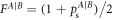 we can solve for Fπ = 83.35%.
The fidelity for a 3-photon GHZ state (or cluster state) can be estimated from these fidelities and corresponding success probabilities as FGHZ = ps + (1 − ps)/8, where seven rotation operations are needed (two π/2 and 5π rotations or two 3π/2 and 5π rotations). We note that the number of spin rotations needed can be reduced by altering the pulse sequence for a GHZ state but not for a cluster state.
5.6. Generation of linear cluster states
The focus here lies on the 3-photon GHZ state but as mentioned in the introduction, the protocol can be modified to generate linear cluster states. As suggested in [16], an additional π/2 spin rotation about the y axis between subsequent photons will accomplish this. With spin rotations being a central part of the scheme, this step can be directly incorporated. Note that a photon here is distributed among two time-bins, so the π/2 pulse is only needed every two photon generation pulses. In step #4 of figure 1, the state would evolve from  to
to  . Following the operations as in the main text, including an additional π/2 pulse between time-bins 4 and 5, it can be seen that the extracted photonic state in the logical basis will be
  . The step by step evolution of the state is written down in the supplementary information is available online at stacks.iop.org/QST/4/025011/mmedia.
Acknowledgments
The authors acknowledge funding from the EPSRC for MBE system used in the growth of the micropillar cavity. J L gratefully acknowledges financial support from the EPSRC CDT in Photonic Systems Development and Toshiba Research Europe Ltd. B V gratefully acknowledges funding from the European Union's Horizon 2020 research and innovation programme under the Marie Skłodowska-Curie grant agreement no. 642688 (SAWtrain).
While completing this manuscript, we became aware of a preprint detailing the implementation of a scheme similar to the one proposed here using nitrogen-vacancy centres in diamond [https://arxiv.org/abs/1812.10338].
Additional information
The experimental data used to produce the figures in this paper is publicly available at https://doi.org/10.17863/CAM.37524.