

Abstract
Kirigami metamaterials can be exploited in stretchable electronics owing to their architecture, which can be leveraged to amplify stretchability, bendability and deformability. Herein, we report a stretchable kirigami-structured poly(3,4-ethylenedioxythiophene) polystyrene sulfonate (PEDOT:PSS)/polydimethylsiloxane (PDMS) polymer composite. The electromechanical response and mechanical behavior of kirigami PEDOT:PSS-coated PDMS and polymer composite specimens were investigated and compared with their non-kirigami counterparts. The kirigami structure exhibited improved electromechanical properties owing to its characteristic architecture. This study illustrates the application of a kirigami polymer composite as a strain sensor for human motion detection.
Export citation and abstract BibTeX RIS

Original content from this work may be used under the terms of the Creative Commons Attribution 4.0 license. Any further distribution of this work must maintain attribution to the author(s) and the title of the work, journal citation and DOI.
1. Introduction
Flexible and stretchable electronic devices have been considered for several applications such as organic light-emitting diodes [1], lithium-ion batteries [2], sensors [3], supercapacitors [4], electronic skin heaters [5], and solar cells [6]. One of their advantages is that they can be mechanically bent, twisted, compressed, and stretched. However, developing thin, stretchable, deformable, and durable structures for electronic devices that can operate under dynamic loading remains a challenge [7].
Several strategies have been explored for creating stretchable structures. The most common method involves mixing brittle and rigid conductive fillers with stretchable polymers, such as polydimethylsiloxane (PDMS) [6] and polyurethane [7]. The disadvantage of this method is that the aggregation of fillers within polymers results in anisotropic mechanical strength and conductivity. Another method, which has been exploited with metals, silver nanowires, carbon nanotubes, and graphene, involves harnessing the mechanical instabilities of wavy or coiled conductive strips attached to a pre-strained elastomeric substrate [8–11]. Other approaches use fractals [12], meshes [13], nano network structures [14], island interconnections [15], helical structures [16], serpentines [17], and origami and kirigami patterns [18, 19]. Among these, serpentine, nano-network, and nanomesh designs of nanomaterials do not have the required characteristics for wearable electronics and electronic skin devices [20] because of their limited mechanical biocompatibility. However, kirigami structures have been demonstrated to be effective in these applications [21].
Kirigami and origami are strategies that involve, respectively, the cutting or the folding of thin sheets, of materials. They have been used to increase the stretchability and reconfigurability of rigid, thin materials. For example, an inelastic substrate can be made highly extensible by creating lines and short cross-connections using cuts [21]. Kirigami-inspired cuts have impacted stretchable and conformable devices by transforming traditionally used elastomers into more flexible and softer materials. Integrating electronic materials into kirigami-inspired patterns has created a new horizon for stretchable and wearable electronics. Conductive polymers have attracted tremendous attention for fabricating highly stretchable conductors owing to their tunable electrical conductivity, low-temperature processability, high optical transparency, light weight, and cost-effectiveness [22]. For example, a highly stretchable and wearable kirigami-inspired thermoelectric device fabricated from poly(3,4-ethylenedioxythiophene) doped with polystyrene sulfonate (PEDOT:PSS) nanosheets on paper exhibited a high Seebeck coefficient of 35 μV K−1 and an optimum power factor of 95 μW m−1 K−1 at 200% applied strain [23]. A stretchable bioelectrode patch was used as a tool to monitor muscular activity for a broad spectrum of physical movements [24]. This patch comprised a kirigami-inspired elastic wiring system and PEDOT:PSS conducting nanosheets that conformed to the skin.
The main challenge for stretchable electronics is maintaining their electrical and mechanical performance (i.e. durability) under high mechanical and cyclic strains. In addition, accommodating multidirectional strain is critical in wearable and stretchable electronics. Most studies have used unidirectional kirigami structures to fabricate extensible conductors [25–27].
This study introduces an isotropic kirigami-inspired device for stretchable electronics based on PEDOT:PSS, which can operate under cyclic loading/unloading conditions. Two material systems were used to fabricate stretchable devices: PEDOT:PSS films deposited on kirigami-structured PDMS substrates and kirigami-structured PEDOT:PSS/PDMS composites. The mechanical properties were evaluated via stress–strain measurements and dynamic mechanical analysis. The electromechanical responses of the two material systems were evaluated and compared to those of non-kirigami. Finally, the kirigami PEDOT:PSS/PDMS polymer composite was evaluated for human motion detection by recording the resistance changes with strain. This study indicates that the combination of kirigami patterns and conducting polymer composites is a valuable strategy to achieve stretchable electronics patterns.
2. Methods
2.1. Specimen preparation
We used six types of specimens: free-standing PEDOT:PSS films, PEDOT:PSS films on PDMS, PEDOT:PSS-PDMS composites, kirigami-structured PDMS, PEDOT:PSS films on kirigami-structured PDMS, and kirigami-structured PEDOT:PSS-PDMS composites.
Free standing PEDOT:PSS films were prepared on a precleaned glass slide by mixing 2% w/w PEG 400, 5% w/w Triton X 100 with PEDOT:PSS (Clevios PH1000) and stirring with a Vortex machine at 2000 rpm for 15 min. The mixture was cured at 100 °C for 2 h.
PDMS was prepared on a precleaned glass Petri dish by mixing the Sylgard-184 (Dow Corning) base and a curing agent at a 10:1 w/w ratio and stirring using a centrifugal mixer at 2000 rpm for 10 min. The mixture was then poured into a mold and cured at 100 °C for 1 h. Prior to PEDOT:PSS coating, PDMS underwent UV/O3 treatment for 35 min to make its surface hydrophilic. The PDMS specimens were finally coated with PEDOT:PSS (screen printing paste, Clevios™S V3 STAB) by spreading the paste with a glass slide through a polyethylene tetrathaplate stencil.
PEDOT:PSS/PDMS polymer composite specimens were prepared by mixing 0.35 g polyethylene glycol (PEG) 400 (Millipore Sigma), 0.5 g Triton X-100 (Millipore Sigma), 5 g PEDOT:PSS (Clevios PH1000, Heraeus Electronic Materials GmbH), 10 g of PDMS base and 1 g of curing agent (Sylgard-184, Dow Corning) using a centrifugal mixer at 2000 rpm for 30 min. Triton improves the miscibility of PEDOT:PSS it PDMS [28]. The mixture was successively poured into a pre-cleaned glass Petri dish and heated at 80 °C for 6 h to avoid bubble formation.
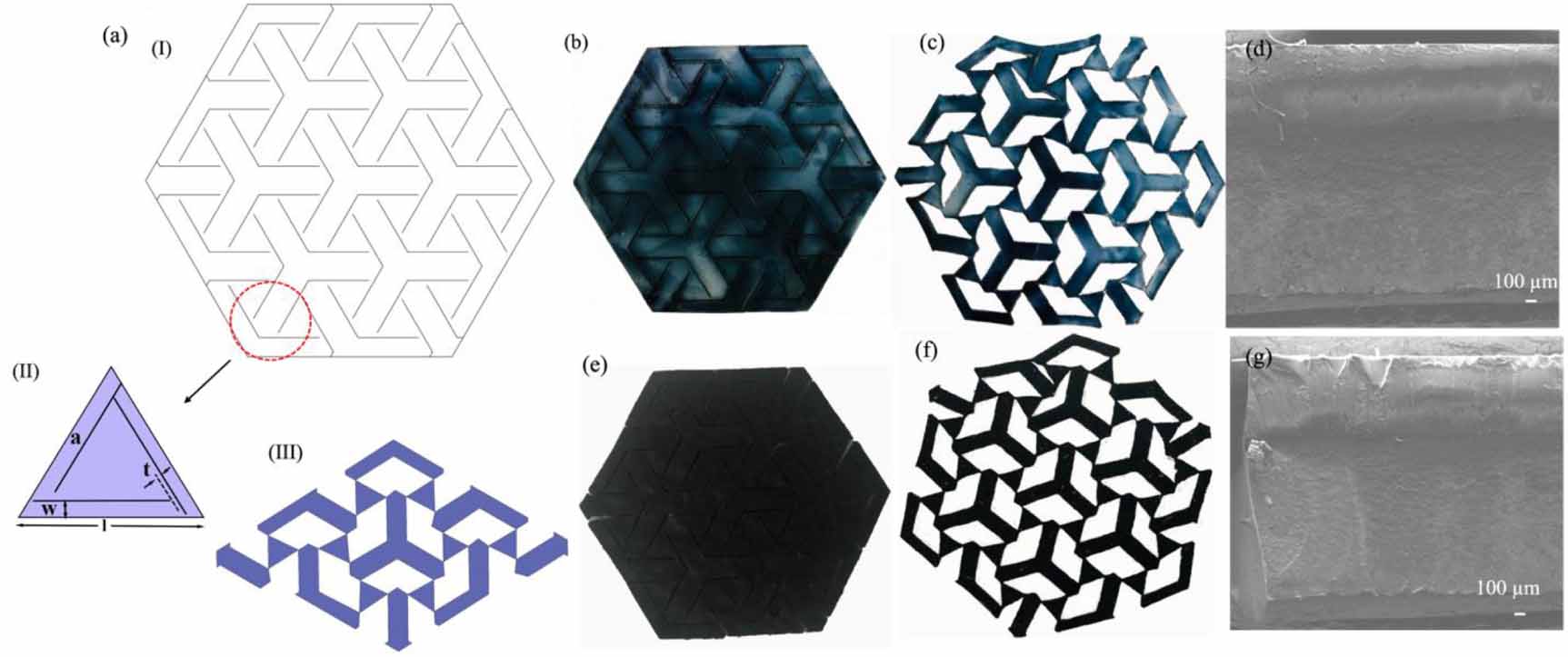
Kirigami specimens were prepared by cutting with a 100 W laser with a speed of 10 mm s−1 and 25% power. To prepare the PEDOT: PSS-coated PDMS specimen, the PDMS was laser-cut before coating. The kirigami-structured samples featured a hexagonal motif with dimensions of 70 mm × 50 mm × 1 mm. Kirigami-based metamaterials consist of periodic patterns with high tunable properties such as stiffness, auxeticity and bistability [29]. An auxetic pattern has a negative Poisson ratio, that is, it becomes thicker in the transverse cross-section when stretched along the longitudinal direction [30, 31]. Bistability means that the structure has two states of equilibrium and can maintain the deployed state when the load is removed. For a bistable auxetic material, the rotation of units leads to bistable snapping [32]. In this study, we used a triangular bistable auxetic pattern with parallel-cut motifs [32] (figure 1(a) (I)). The length of the rotating unit was half of the building block ( ), and ligament size between the cuts and the edge lengths was t = 1 mm (figure 1(a)(II) and (III)). Photographs of the kirigami-structured PEDOT:PSS-coated PDMS and polymer composite in closed and open forms are shown in figures 1(b), (c), (e) and (f), respectively. Figures 1(d) and (g) show the uniform thicknesses of the kirigami PEDOT:PSS-coated PDMS and kirigami composite, respectively.

Figure 1. (a) Scheme of a kirigami pattern in its closed state (I), dimensions of the rotating unit (II), and opening state of a collection of units (III); (b), (c) photographs of kirigami PEDOT:PSS-coated PDMS specimen in closed and deployed states, and (d) SEM cross section of a kirigami PEDOT:PSS-coated PDMS specimen, (e), (f) Kirigami composite specimen in closed and deployed state with SEM cross section of its thickness (g).
Download figure:
Standard image High-resolution image2.2. Specimen characterization
The surface morphology of PEDOT:PSS deposited on the PDMS substrate was studied using an optical microscope (Zeiss Axiocam 105) and a scanning electron microscope (Hitachi TM3030).
A multi-axial mechanical tester (Mach-1 model v500csst, Biomomentum, Canada) was used to characterize the mechanical properties of the specimens (dimensions:45 mm × 15 mm and 1 mm thickness). The applied force was measured during the tests using a 70 N load cell. The mechanical tests were performed according to ASTM D882. The Young's modulus (E) of each specimen was obtained from the slope of the force-displacement curve in the elastic region along the loading path [33]. The elongation at break of the specimens was calculated to determine their stretchability [33]. The equations used to calculate Young's modulus and elongation at break are provided in the supplementary data. Each test was repeated three times to calculate the average values and standard deviations of the Young's modulus and elongation at break.
The viscoelastic behavior of the samples was studied using cyclic and dynamic mechanical tests at room temperature. Cyclic tests were performed by applying pre-strain values (25%, 35%, 45%, and 55%) at a constant axial strain rate of 1 mm s−1. In addition, cyclic loading/unloading tests were conducted at 25% strain for 500 cycles, which is sufficiently high to stabilize the specimen response. At a 25% strain, the kirigami specimens opened entirely. The dynamic tests were performed by applying an axially sinusoidal strain on the samples at a frequency of 0.5 Hz, a speed rate of 1 mm s−1 at room temperature.
The electromechanical properties were measured using a customized uniaxial translational manipulator coupled with an electrical source measure unit (Agilent B2902A) in constant voltage mode. The electromechanical responses of the samples subjected to the given strains were recorded until they broke. The electrical durability of the non-kirigami and kirigami specimens was investigated under 1000 and 5000 loading/unloading cycles, respectively, at 25% strain. The lower number of cycles for the non-kirigami specimens was due to sample damage.
2.3. Kirigami strain sensor
Kirigami-structured composites were used as strain sensors. The specimen was attached to the wrist of a volunteer using a double-sided tape. Subsequently, using ultrathin copper wires, both ends of the kirigami were connected to an electrical circuit in series with a known resistor. Using an Arduino Uno board, a prescribed voltage was applied to the circuit, and the change in resistance of the kirigami was monitored by measuring the voltage across the known resistor and using the voltage-divider rule.
3. Results and discussion
3.1. Tensile response
Uniaxial tension was applied to the specimens to determine their tensile response. To obtain a benchmark for comparison, we first investigated the response of the base materials (free-standing PEDOT:PSS films and PDMS films) and non-kirigami specimens (figure 2(a)). Under monotonic stretching, all the specimens exhibited a nonlinear stress–strain relationship. Free-standing PEDOT:PSS films showed significantly lower elongation at break than all other specimens (figures 2(a) and (b)). Interestingly, coating PDMS with PEDOT:PSS leads to a decrease in the elongation at break and an increase in Young's modulus. The serrated tooth region in the non-kirigami PEDOT:PSS-coated PDMS specimen is attributed to the presence of cracks formed on the surface of the PEDOT:PSS coating owing to the applied stress. The composite specimens showed the smallest Young's modulus and the largest elongation and break. The Young's modulus (∼0.20 MPa) of the non-kirigami polymer composite specimen was lower than those of the non-kirigami PEDOT:PSS-coated PDMS specimen (∼2.0 MPa) and non-kirigami PDMS specimen (∼0.75 MPa) (figure 2(c)).
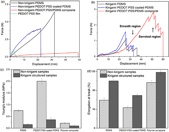
Figure 2. (a) Force-displacement curves of a representative non-kirigami specimen; (b) force-displacement curves of a representative kirigami structured specimen; (c) Young's modulus and (d) elongation at break of non-kirigami and kirigami structured specimens. Error bars represent standard deviations obtained by repeating the tensile tests thrice for each specimen.
Download figure:
Standard image High-resolution imageThe force-displacement curves of the kirigami specimens (figure 2(b)) comprised two parts: a smooth region (part I) followed by a serrated tooth region (part II). The peaks and valleys in the smooth region (part I) are caused by snap-through instabilities induced by the rotating ligaments. The serrated tooth region occurs when the individual hinges of the kirigami specimen begin to break. In this region, we observe a sequential failure mechanism of the individual hinges. The breakage of each hinge causes a drop in the force-displacement curve. Compared to non-kirigami specimens, the kirigami counterparts showed a lower Young's modulus and a higher elongation at break (figures 2(c) and (d)), with the PEDOT:PSS/PDMS composite displaying a lower Young's modulus and the highest elongation at break. The PEG in the polymer composite acted as a plasticizer [34] and increased the elongation at break to ∼110% (figure 2(d)). In addition, mixing PDMS with Triton X-100 increased the miscibility of PEDOT:PSS in PDMS and thus improved the stretchability (elongation at break) [28]. For the kirigami-structured polymer composite, the elongation at break was ∼15% higher than that of the kirigami-structured PDMS specimen and ∼40% higher than that of the kirigami PEDOT:PSS-coated PDMS specimen (figure 2(d)). The values of Young's modulus and elongation at break are listed in table 1.
Table 1. Values of Young's modulus and elongation at break for the non-kirigami and kirigami specimens.
| Sample | Young's modulus (MPa) | Elongation at break (%) |
|---|---|---|
| Non-kirigami PDMS | ∼0.75 | ∼70 |
| Non-kirigami PEDOT:PSS coated PDMS | ∼2.00 | ∼50 |
| Non-kirigami polymer composite | ∼0.20 | ∼110 |
| Kirigami PDMS | ∼0.55 | ∼112 |
| Kirigami PEDOT:PSS coated PDMS | ∼0.35 | ∼78.00 |
| Kirigami polymer composite | ∼0.10 | ∼133 |
3.2. Loading-unloading cyclic tests
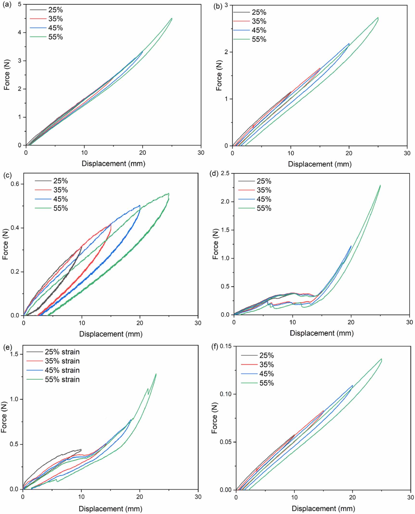
Figure 3 shows the cyclic loading/unloading of a representative sample for each material system at the prescribed strain values (25%, 35%, 45%, and 55%). The plastic deformation (i.e. residual strain) was close to zero for one loading/unloading cycle for all the samples at 25% strain. In addition, we noticed load-induced softening due to the Mullin effect caused by microstructural damage to the base material [35]. This phenomenon is typically observed in elastomers, which exhibit an increasingly compliant response after the first cycle of load before stabilization [36]. The peaks and valleys in the response of the kirigami-structured specimens were caused by snap-through instabilities. In addition, the maximum force required for stretching the composite specimens was lower than that of the other specimens. The loading/unloading results reveal that composite specimens are softer than PDMS and PEDOT:PSS-coated PDMS, and hence have improved stretchability.

Figure 3. Loading/unloading cycles of (a) non-kirigami PDMS specimens, (b) non-kirigami PEDOT:PSS coated PDMS specimens, (c) non-kirigami polymer composite specimens, (d) kirigami PDMS specimens, (e) kirigami PEDOT:PSS coated PDMS specimens, and (f) kirigami polymer composite specimens at 25%, 35%, 45% and 55% strains.
Download figure:
Standard image High-resolution imageTo study the viscoelastic behavior under cyclic deformation, each sample was exposed to 500 loading/unloading cycles at 25% strain and a strain rate of 1 mm s−1 (3 h) (figure 4). All samples showed stress softening and hysteresis, owing to their viscoelastic properties and microstructural damage occurring during loading (figures 4(a)–(c) and (e)–(g)) [35]. The area within the hysteresis loop represents the energy loss (the larger the area within the boundary, the higher is the energy loss). The energy loss manifested as a hysteresis loop when the specimens were cycled between 0% and 25% strains. Although the hysteresis can be typically attributed to molecular network reorientation [37], the kirigami specimens did not experience significant plastic deformation when they were subjected to loading/unloading up to 25%. By calculating the area of each loop for the first cycle, we noticed that the energy dissipation (∼ 0.8 J) in the kirigami PEDOT: PSS-coated PDMS specimen was significantly lower than that of non-kirigami specimens (∼1.5 J) (figure S2). A similar trend, with a less significant difference, was observed for the polymer composite samples, for which the energy loss was ∼0.7 J for the non-kirigami and ∼0.3 J for the kirigami samples. The energy dissipation decreased during the first loading/unloading cycles and stabilized after a certain number of cycles (figures 4(d) and (h)) [36]. For example, it stabilized after the third cycle for the for the kirigami-structured polymer composites, after 100 cycles for PEDOT: PSS-coated PDMS and after 250 cycles for PDMS. A similar result was found for non-kirigami specimens. However, in the non-kirigami PEDOT:PSS-coated PDMS, the energy dissipation decreased dramatically at the 150th cycle and then remained constant until the 250th cycle.
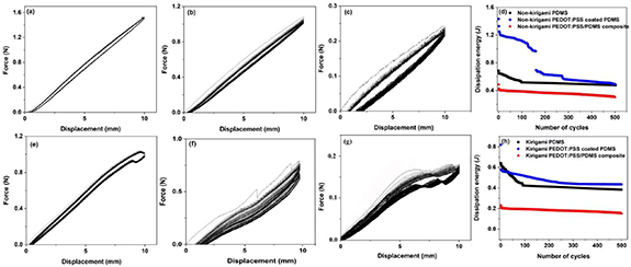
Figure 4. Fifty cycles of loading/unloading under 25% strain at a strain rate of 1 mm s−1 and room temperature for (a), (b), (c) non-kirigami, and (e), (f), (g) kirigami-structured PDMS, PEDOT:PSS-coated PDMS, and polymer composite, respectively; energy dissipation for 500 loading/unloading cycles for (d) non-kirigami and (h) kirigami structured samples.
Download figure:
Standard image High-resolution imageThe viscoelastic effect in the samples appeared as plastic deformation (i.e. residual strain). After 500 loading/unloading cycles, the residual strain was below 1.0% for the kirigami polymer composite, 2.5% for the kirigami PEDOT:PSS coated PDMS, and 2.0% for the kirigami PDMS. The residual strains for the non-kirigami PEDOT:PSS-coated PDMS, polymer composite, and PDMS specimens were ∼5.0%, 2.2%, and 3.5%, respectively. As a result, the kirigami samples showed a more elastic response than the non-kirigami ones.
In addition, in comparison to the initial stress, the stress in the second cycle decreased and remained approximately constant for the remaining cycles (figure 4) [34], thus showing a softening effect.
3.3. Dynamic mechanical test
Dynamic mechanical properties are usually described by the complex dynamic modulus (E*), which has two components: storage (E') and loss modulus (E'). The former represents the material stiffness, and the latter describes the loss of energy within the material through plastic deformation, accrued in this case by the morphological changes and molecular motion of the polymer chains. The expressions for the modulus are [38]:
where σm is the stress amplitude, em the strain amplitude, 'fm ' the force amplitude, 'A' the sample area, 'L' the length of the sample and 'ΔL' the displacement
The loss factor (tanδ) is calculated from the ratio between E' and E''. ' ' is the angular phase shift or loss angle between stress and strain [38]. The value of '
 ' is also expressed as the delay between applied strain and stress.
The values of 'δ', 'tanδ', 'E*
', 'E'', and 'E''' are listed in table 2. The stress was less phase-shifted (low δ) for kirigami-structured samples. Generally, the value of δ is  . A value closer to zero degree denotes a more elastic material as opposed to one close to 90° implies to a viscoelastic material. In addition, tanδ below one is typical of a viscoelastic solid at a given frequency. The kirigami polymer composite showed a more elastic behavior as it had δ equal to 1.5, which was less than δ of other specimens. In addition, the storage and loss moduli decreased for the kirigami samples, which indicated a decrease in the elastic stiffness of the material.
Table 2. Values of δ, tanδ, E*, E', and E'' for the non-kirigami samples and kirigami specimens.
| Sample | δ (°) | tanδ | E* (MPa) | E´ (MPa) | E˝ (MPa) |
|---|---|---|---|---|---|
| Non-kirigami PDMS | ∼4.4 | ∼0.08 | ∼0.76 | ∼0.76 | 0.06 |
| Non-kirigami PEDOT:PSS coated PDMS | ∼10 | ∼0.18 | ∼2.50 | ∼2.45 | 0.43 |
| Non-kirigami polymer composite | ∼2.3 | ∼0.04 | ∼0.25 | ∼0.25 | 0.010 |
| Kirigami PDMS | ∼2.1 | ∼0.04 | ∼0.14 | ∼0.14 | 0.005 |
| Kirigami PEDOT:PSS coated PDMS | ∼3.4 | ∼0.06 | ∼0.29 | ∼0.29 | 0.017 |
| Kirigami polymer composite | ∼1.5 | ∼0.03 | ∼0.09 | ∼0.09 | 0.002 |
3.4. Electromechanical properties
The electromechanical properties of the kirigami and non-kirigami specimens were studied under various applied strains for the coated specimens (figure 5(a)) and composites (figure 5(b)). It is worth noting that the kirigami specimens were open when the strain was applied and closed when the strain was removed.
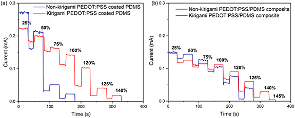
Figure 5. Current versus time at given applied strains for (a) non-Kirigami and Kirigami PEDOT: PSS-coated PDMS and (b) non-kirigami and kirigami polymer composite specimens. Measurements performed under a constant applied voltage of 10 mV.
Download figure:
Standard image High-resolution imageFor all the specimens, the current decreased with increasing strain and dropped to the noise level when the specimen broke. As described in the supplementary data, cracks and wrinkles disrupted the current pathways; hence, the current decreased with stretching (figures S3–S6, supplementary data). Upon release, the open cracks partially reconnect, and the current partially recovers. For kirigami specimens, the current decreases in the open position, and the generation of cracks and fractures near the hinges causes current reduction upon cycling. For the PEDOT-coated specimens, there was a significant difference in the electromechanical properties between the kirigami and non-kirigami specimens. The former could withstand a strain of ∼140%, whereas the latter broke at ∼120% strain. In addition, the non-kirigami samples experienced a larger current decrease at the same applied strain. For the composite specimen, the difference between the kirigami and non-kirigami specimens was less significant, as the former broke at ∼125% strain and the latter broke at ∼145% strain. Moreover, the decrease in current upon strain was very similar for the two specimens.
Figure 6 shows the current versus time plots for 1000 stretching/releasing cycles at 25% strain for non-kirigami coated (6(a)) and composite (6(b)) specimens. The insets show the current change during the first 40 s. The PEDOT:PSS-coated PDMS specimen exhibited a significant current reduction of 40% at the beginning of stretching/releasing (figure 6(a)), likely due to the formation of wrinkles and cracks (figure S3). For the polymer composite specimen, the current decreased by 10% after 1000 stretching/releasing cycles (figure 6(b)). In both cases the current stabilized after 1000 cycles.
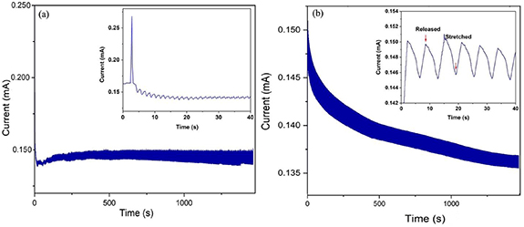
Figure 6. Current-time graphs for 1000 stretching/releasing cycles under 25% strain for (a) non-kirigami PEDOT:PSS-coated PDMS specimen and (b) non-kirigami polymer composite specimen. Inset shows the change in current during the first 40 s of cyclic opening and closure. Measurements performed under a constant applied voltage of 10 mV.
Download figure:
Standard image High-resolution imageFigure 7 shows the current versus time plots of coated (7(a)) and composite (7(b)) kirigami specimens subjected to 5000 opening/closing cycles. The insets show the current change during the first 40 s. The length of the sample was 4 cm in the closed form and 5 cm (strain = 25%) in the open form. In the PEDOT:PSS-coated PDMS samples, the current amplitude monotonically decreased as the strain increased (figure 7(a)). To understand the overall behavior of the plot, the current values between the open and closed states were compared in the first and the last cycle (5000th) cycle. After the first cycle, the change in current between the closed and open states (ΔI1st) was less than 10% (inset of figure 7(a)), whereas it was ca. 30% after 1000 cycles. By considering the current of non-kirigami (discussed previously for figure 6(a)) and kirigami PEDOT:PSS-coated PDMS samples at 1000 opening/closing cycles, we concluded that the electromechanical durability improved by ∼10%. The current decreased by ∼55% in both the closed and open state after 5000th cycles. In the kirigami structure, PEDOT:PSS was well connected via hinges, through which the charge carriers traveled across the entire perforated structure. During the opening and closing cycles, these hinges flexed at a given angle, pointing in one direction. When the structure was opened or closed, an individual hinge experienced a certain amount of strain. The total strain-induced elastic energy was redistributed among all hinges. Therefore, wrinkles and cracks were formed through the microstructure of the samples and were responsible for the current decrease (see figure S4).
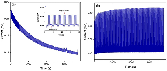
Figure 7. Current-time graphs of (a) kirigami PEDOT:PSS-coated PDMS specimen under 5000 opening/closing cycles at 25% strain. Inset shows current change in the first 5 s. Inset shows the change in current undergone by the sample during the first 40 s of cyclic opening and closure. (b) Current-time graphs of kirigami polymer composite specimen under 5000 opening/closing cycles at 25% strain.
Download figure:
Standard image High-resolution imageFigure 7(b) shows the current-time graphs of the kirigami-structured polymer composite sample. We observed that the current amplitude remained approximately stable even after 5000 opening/closing cycles. Triton X-100 has a hydrophobic tail and hydrophilic head [36], which may interact with PDMS via the hydrophobic part and with PEDOT:PSS via the hydrophilic part [24]. The strong intermolecular force between the polymer composite elements and the improvement in the mechanical properties by PEG and Triton X-100 made the polymer composite durable. The current did not decrease throughout the 1000 opening/closing cycles and decreased by only ∼3% after 5000 opening/closing cycles.
3.5. Kirigami strain sensor
Kirigami-structured PEDOT:PSS/PDMS polymer composites can be used as conductors in flexible and stretchable electronic devices, owing to their conductivity and reliability. In addition to their application as conductors in electronic devices, they can also be used as strain sensors.
A fundamental parameter of strain sensors is their sensitivity to strain, expressed by the gauge factor (figures 8(a) and (b)), which describes the change in electrical resistance during stretching [39]. The gauge factor increased linearly with strain from ∼0.3 to ∼1.7 for the kirigami polymer composite and from ∼0.6 to ∼1.3 for the kirigami PEDOT:PSS coated PDMS when the strain changed from 25% to 95%.

Figure 8. ΔR/R0 versus strain for (a) non-kirigami and (b) kirigami specimens at different strains; ΔR/R0 for stretching and releasing for (c) kirigami-structured PEDOT: PSS-coated PDMS and (d) kirigami-structured polymer composite specimens. Error bars represent standard deviations. To obtain the standard deviation, the current was measured for three different kirigami PEDOT:PSS-coated PDMS and kirigami polymer composite specimens in the opening/closing states at specific strains.
Download figure:
Standard image High-resolution imageThe resistance changes for the stretching and strain release are shown in figures 8(c) and (d). The corresponding hysteresis is given by:
where 'Rs ' and 'Rr ' are the resistance at stretching and releasing states, respectively and 'Rm ' is the maximum value of resistance at a specific strain. The relative resistance changes exhibited negligible hysteresis (∼3.5%) for kirigami PEDOT: PSS-coated PDMS and polymer composite specimens.
The advantage of using a kirigami-structured sensor can thus be evinced by comparing the change in resistance that results from an applied strain. This is shown in figures 8(a) and (b). For example for 100% strain, the change in resistance of non-kirigami PEDOT:PSS coated PDMS is 5 times higher than that of kirigami PEDOT:PSS coated PDMS. A similar advantage can be observed by comparing the resistance changes of the non-kirigami PEDOT:PSS/PDMS composite. The former is 4 times higher than that of the latter.
To demonstrate the application of the kirigami polymer composite for human body movement detection, we attached the specimen to a human wrist (figure 9). An electrical circuit (based on the schematic shown in the inset of figure 9) was used to record the generated signals. When the wrist was bent up or down, the kirigami-structured sample stretched and switched to the open state; consequently, the resistance increased. In contrast, the resistance was constant when the wrist remained in a neutral position, because the kirigami-structured sample remained in its closed state (supporting movie 1).

Figure 9. Resistance variation by wrist bending. The insets show an optical image of the device on the arm of a volunteer and the scheme of the electrical circuit used for detecting the signals generated by wrist bending.
Download figure:
Standard image High-resolution image
4. Conclusion
The present study highlighted the electromechanical response of two types of kirigami specimens prepared using a laser cutting technique and compared systems based on coatings and composite materials. The mechanical behavior and electromechanical response of kirigami polymer composite specimen were compared to non-kirigami and kirigami PEDOT:PSS coated PDMS and non-kirigami polymer composite specimens. The mechanical behavior of the kirigami specimens differed from that of the non-kirigami specimens. The kirigami samples showed nonlinear and serration regions in their mechanical responses. The serrated regime started at the instant of the first hinge failure and continued until breakage of the remaining hinges. Kirigami polymer composite exhibited current stability and durability for many opening/closing cycles (i.e. 5000 cycles). However, the current response of the kirigami PEDOT: PSS-coated PDMS decreased over 5000 opening/closing cycles. Cracks and wrinkles generated by cyclic strain led to changes in the current amplitude in the non-Kirigami and Kirigami specimens. In addition, we examined the effect of PEDOT:PSS coating on non-kirigami- and kirigami-structured PDMS substrates. For the non-kirigami and kirigami samples, the PEDOT:PSS coating increased the stiffness and decreased the elongation at break. Finally, the application of the kirigami polymer composite was assessed for human motion detection. Although the performance of our conductors still cannot rival that of PDMS/carbon nanotube composites [26], this work paves the way for the development of stretchable and deformable electronic devices based on kirigami-inspired conducting polymers.
Acknowledgment
This research was supported by the Natural Science and Engineering Council Canada (NSERC) through Discovery Grants awarded to FC and DP and Defence Research and Development Canada through an IDEaS Micronet (CFPMN1-008) Grant awarded to FC and DP. The equipment and infrastructure used in this study were acquired and maintained by the Canada Foundation for Innovation. PK acknowledges the Pierre Arbour Foundation and NSERC for a Master's scholarship. MA acknowledges the Trottier Energy Institute for a Master's scholarship.
Data availability statement
All data that support the findings of this study are included within the article (and any supplementary files).
Ethics statement
The protocol for the human experiments was approved by the ethical committee of Polytechnique Montreal (Approval Number CER-2021-04-D).
Conflict of interest
The authors declare no conflicts of interest.
Supplementary data (9.3 MB MP4)
Supplementary data (5.4 MB DOCX)