

Abstract
Smart contact lenses with continuous intraocular pressure (IOP) sensors are emerging as an alternate system for monitoring the progression and treatment of glaucoma. To date, such sensors have primarily consisted of strain gauges embedded on traditional contact lenses. This work presents a novel smart contact lens design consisting of a ring-shaped contact lens with a piezoresistive strain gauge. We observe an increase in IOP measurement sensitivity of the device with an increase inner diameter of the ring. Ring-shaped sensors with an inner diameter of 2.7 mm show an increase in sensitivity of up to 7.1% and ring-shaped sensors with an inner diameter of 4.7 mm show an increase in sensitivity of up to 17.9%. It is expected that by incorporating a ring-shaped lens, other strain gauge-based smart contact lenses in the literature would experience similar increase in sensitivity.
Export citation and abstract BibTeX RIS

Original content from this work may be used under the terms of the Creative Commons Attribution 4.0 license. Any further distribution of this work must maintain attribution to the author(s) and the title of the work, journal citation and DOI.
1. Introduction
Glaucoma is an eye disease which is the leading cause of irreversible vision loss [1–3]. Glaucoma does not usually present symptoms other than vision loss, which often happens so slowly that a person may lose a significant portion of their vision before the disease is detected [3]. This makes it particularly difficult diagnose and monitor the disease's progression.
There are several different types of glaucoma, most of which are associated with an elevation in intraocular pressure (IOP) [1, 2]. People with glaucoma typically have IOP above 21 mm Hg [1, 2]. A chronic elevation in IOP is associated with structural damage to the optic nerve, leading eventually to the vision loss associated with glaucoma [1–4]. Glaucoma is treated using a variety of methods such as eye drops, medication, and laser surgery, all of which aim to lower a person's IOP [2]. Treatment and disease progression can be monitored by measuring the IOP.
IOP can be measured in several ways, the most common of which is tonometry. Tonometry works by measuring the amount of force necessary to deform the cornea. Most tonometry tests are performed using specialized equipment in a physician's office. However, studies have shown that IOP can vary diurnally and due to other environmental factors, such as body position [5, 6]. Therefore, devices which offer continuous IOP measurement are currently generating considerable research interest as they can capture the full range of IOP fluctuation throughout the day, as opposed to discrete IOP measurements made via tonometry [1].
An example of a commercialized continuous IOP measurement device is Sensimed Triggerfish [7]. This, and other continuous IOP measurement devices work by detecting the change in shape that the eye experiences when it deforms due to a change in pressure via strain sensors embedded on contact lenses [7–12]. These types of devices are often referred to as smart contact lenses. As far as the authors are aware, such devices have exclusively been embedded on conventional contact lenses, resembling the lenses used for correcting vision. In this work, we present a novel smart contact lens using an embedded strain gauge. We show that by using a ring-shaped contact lens to measure IOP, as opposed to a traditionally shaped contact lens, we can observe increased sensor response. This increase in response is caused by the greater strain experienced in the ring-shaped contact lens when IOP increases compared to the traditional contact lenses.
The increase in IOP causes the radius of curvature of the cornea to increase [13]. Contact lenses have a frictional interaction with the eye. We hypothesize that for lenses with holes, this means that the eye is free to expand inside the inner edge of the hole, which pushes the lens outwards leading to a greater circumferential strain. For lenses without holes, the contact lens will be pushed forward as the lens expands, and experience less circumferential strain relative for the lens with holes. This increase in strain for lenses with holes is demonstrated by making experimental measurements as well as with numerical analysis. This result means that other smart contact lenses, which also use embedded strain gauges to detect IOP, may be able to increase response by using a similar ring shape. Further, using a ring-shaped lens instead of a traditional contact lens has other potential upsides, such as increasing oxygen flow to the eye and not interfering with vision [14]. Because smart contact lenses usually do not correct vision, it is possible to remove the central piece of the lens. Thus, people who require vision correction would need to wear glasses, rather than relying on contact lenses such as the one we describe herein.
2. Design and fabrication
In this work, continuous IOP sensors on conventionally shaped contact lenses and ring-shaped contact lenses were development. Computer aided design was used to model each device type and can be seen in figures 1(a) and (b). Figures 1(c) and (d) show complete samples. The contact lens is made from polydimethylsiloxane (PDMS) mixed at a ratio of 15:1 base to curing agent. The device is patterned with a circular channel of silver nanowires (AgNWs) that is 1.5 mm in width. The channel wraps nearly around the circumference of the device, until the channel descends to the electrical connection points. The sensing mechanism is based on the piezoresistive property of AgNW networks. When AgNWs are deposited on a substrate, they form an interconnected electrically conductive network. When subjected to strain, the resistance of such a network increases due to disconnections which occur at some of the junctions between individual AgNWs [15]. This property has been well-explored and used in a variety of sensors and devices, such as strain gauges, human motion detectors, and other wearable sensors [15–17].

Figure 1. (a) (Top left) CAD model of lens without hole. (b) (Top right) CAD model of lens with 4.7 mm hole. (c) (Bottom left) Lens with no hole. (d) (Bottom right) Lens with 4.7 mm hole. Blue plastic is a convex base for positioning the lenses and is not part of the sensor.
Download figure:
Standard image High-resolution imageThe manufacturing procedure follows a process similar to what has previously been described by this research group [18]. First, PDMS is mixed at a ratio of 15 parts base to 1 part curing agent and degassed in a vacuum for 30 min. Next, it is poured into a reusable contact lens-shaped aluminium mould and degassed for another 30 min. This mould has been manufactured in such a way to produce a contact lens with a depressed channel where the AgNWs will later be deposited. The channel has a depth of 150 µm, which serves to contain the AgNWs within the patterned region. After the second degassing step, the mould is placed in an oven at 60 °C for 60 min. The lens is then removed from the mould and treated with a corona surface treater to make the surface of the PDMS more hydrophilic. Then, AgNWs (purchased from Sigma Aldrich) in an ethanol solution are deposited into the channel of the contact lens. The concentration of the nanowire solution used is 5 mg ml−1. The nanowires have an average width of 70 ± 10 nm and an average length of 40 ± 5 µm. The 50 µl of AgNW/ethanol solution is deposited at a time and the ethanol is allowed to evaporate for 10 min. After evaporation, this step is repeated until a total of 200 µl has been deposited. Successive rounds are deposited to increase the electrical conductivity of the device to ensure samples with low and stable resistance. After the final round of AgNWs are deposited any excess AgNWs that overflowed the channel are removed using an isopropyl alcohol-soaked swab. Excess PDMS is trimmed away from the outer edge of the contact lens using a 15 mm punch. Copper tape used for the electrical connections is then placed on the connection points of the lens. A separate top piece of PDMS is prepared using the same procedure that is used to prepare the contact lens. This top piece of PDMS is then bonded to the contact lens using three small drops of PDMS. This is done to ensure the AgNWs are sealed completely inside PDMS and the eye or the eyelid will not be exposed to AgNWs when the lens is worn. Sample devices can be seen above in figures 1(c) and (d). To manufacture the ring-shaped contact lenses, an extra step at the end of manufacturing is used wherein a circular punch of either 2.7 or 4.7 mm is used to remove a circular portion of PDMS from the centre of the lens. The completed device has a total thickness of approximately 350 µm, which is thinner than commercially available continuous IOP monitoring devices such as Sensimed Triggerfish, which has a thickness of 585 µm [6].
3. Numerical model
ANSYS was used to perform finite element analysis of the behaviour of the lenses on a model of the human eye. An image showing the geometrical configuration of the eye and of the lens are shown in figure 2. For this analysis, a simplified model of the eye consisting of only the cornea and a portion of the sclera is included. The cornea and sclera each have a thickness of 0.5 mm, based on experimental measurements [19, 20]. Determining what material properties to assign the eye is difficult, as a wide range of values have previously been reported in the literature. A Young's modulus of 0.3 MPa was selected for both cornea and sclera in this analysis, as this is a figure commonly reported [21, 22], however it should be noted that some other studies have suggested somewhat higher values [19, 20]. It is also challenging to determine what material properties to assign the PDMS contact lens, as the material properties of PDMS are sensitive to a variety of factors during the curing process, including curing time and curing temperature. A Young's modulus of 1.32 MPa was used for PDMS based on measurements of the material's Young's modulus when prepared using similar curing temperatures and durations [23]. Both materials were modelled as linearly elastic materials, which is a good approximation considering the low strain observed in this model.

Figure 2. This image shows the configuration that was used for the numerical analysis. The lens (lighter material) sits atop an eye (darker material) consisting of a cornea and the top half of the sclera.
Download figure:
Standard image High-resolution imageThe expansion of the contact lens was investigated by simulating a pressure increase on the inner wall of the cornea and sclera. To quantify the performance of the contact lens, the change in length of the AgNW channel is measured. This analysis is performed using contact lenses that resemble traditional contact lenses, referred to as lenses with no holes as well as lenses with central holes 2.7 and 4.7 mm in diameter. Measurements of change in length of the channel are made from 0 to 40 mm Hg, in increments of 5 mm Hg. Figure 3 shows the strain that is developed by the different lenses at 40 mm Hg. The strain occurring in the channel is slightly higher for both lenses with holes.
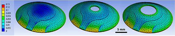
Figure 3. From left to right, lens with no hole, lens with 2.7 mm hole, lens with 4.7 mm hole. This shows the maximum principal strain experienced by the lenses when the pressure of the eye is 40 mm Hg. Scale bar in black at bottom is 5 mm. Scale bar to the left is strain in units of mm mm−1.
Download figure:
Standard image High-resolution imageThe results of this analysis are shown in figure 4. Plotted on the y-axis is the per cent increase in channel length, ΔL/L0, where L0 is the unstretched length of the channel and ΔL is the change in channel length at a given pressure. The data demonstrates an increase in ΔL as pressure increases for all samples. Additionally, when a hole is present in the centre of the lenses, ΔL increases at a given pressure. This means that when introducing a ring-shaped lens, rather than a traditional contact lens, the change in length of the sensing element will be increased at a given pressure. For a piezoresistive sensor such as this, this means that greater sensitivity for IOP detection can be achieved, where sensitivity is defined as the ratio of change in pressure divided by the change in resistance. This is because a larger change in channel length will cause a larger change in resistance of the AgNW network.

Figure 4. The change in length, ΔL, normalized to original unstretched length, L0, for the three different types of lenses. A polynomial of degree 2 is fit to the data shown here.
Download figure:
Standard image High-resolution imageThe results observed in this simulation show a polynomial relationship of degree 2 between pressure and change in channel length. The lines show very good correlation with the data, with R2 > 0.9999 for all three lens types. The increase in relative sensitivity between lenses with holes and conventional lenses can be obtained by taking the equation for either lens with hole then dividing by the equation for the lens with no hole. The lens with the 2.7 mm hole sees an increase in ΔL/L0 of approximately 5.5%, and the lens with the 4.7 mm hole sees an increase of 19.7% when compared to the lens with no hole. These values were nearly constant over the interval of 0–40 mm Hg. This is a significant enhancement to the sensitivity of the lens.
4. Experimental results
4.1. Porcine eye results
The contact lenses were tested experimentally on enucleated porcine eyes. Porcine eyes were chosen due to their similarity to human eyes in size, shape, and material properties. A schematic of the testing apparatus is shown in figure 5(a). Figure 5(b) shows a picture of the lens on the porcine eye with several important components labelled. The lenses were placed on the porcine eyes and measured using electrical probe stations connected to an ohmmeter. The internal pressure of the porcine eyes was measured using a pressure catheter that was inserted into the eye via a small hole. The pressure of the eye was varied by injecting water into the eye through a small tube via syringe pump. When testing the lenses, the pressure of the eye was increased and then allowed to return to baseline pressure multiple times to ensure repeatability of the trial.
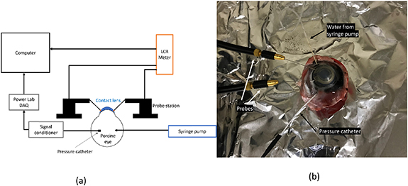
Figure 5. (a) (Left) The equipment used to test the behaviour of contact lenses on an enucleated porcine eye. (b) (Right) A photo of a lens on a porcine eye, with the pressure catheter, the electrical probes, and the water tube visible.
Download figure:
Standard image High-resolution imageFigure 6(a) demonstrates the behaviour of a lens with no hole on a porcine eye. The pressure of the eye is repeatedly increased via syringe pump, and the resistance of the lens is measured. There is some instability over the first few cycles, after which the resistance measured by the sensor closely matches the pressure of the eye. In figure 6(b), the individual cycles are separated and plotted with respect to pressure, and a linear relationship is observed. Cycles 1–3 have more noise a steeper slope than the cycles 4–8. After this initial period, extremely repeatable results are seen. The linear fits have R-values from 0.82 to 0.97, indicating good linearity.
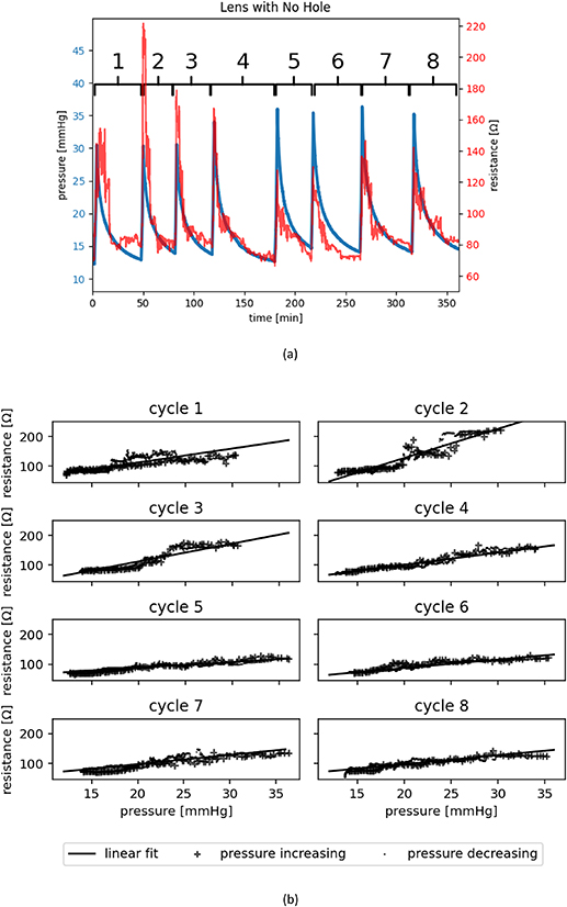
Figure 6. (a) (Top) The response of a contact lens with no hole to repeated pressure cycling. The numbers in black identify the start and end point for the individual cycles. (b) (Bottom) The individual cycles are separated, and a linear fit is applied.
Download figure:
Standard image High-resolution imageMeasurements of lenses with holes were also made using the same apparatus to observe whether adding a hole produced greater sensitivity when tested experimentally. Drawing direct comparisons between separate lenses is difficult, since there is not perfect consistency between different samples. The lenses have unique initial resistances, r0, as well as having unique gauge factors, the slope of the resistance with respect to pressure. Other factors, such as differences in the size of porcine eyes or any difference in placement of the lens relative to the eye could also affect lens behaviour. To minimize differences between trials as far as possible, a lens without a hole was tested on a porcine eye and the response of the lens to pressure was measured. Afterwards, a hole of 4.7 mm in diameter was added to the lens, and the same lens was tested again.
The behaviour of the same lens, with and without a hole, can be seen in figure 7(a). When the hole is added, the sensitivity increases. However, an increase in r0 is also observed. This may be caused by changes to the AgNW network that occur during the process of punching a hole in the lens, or it could also be from differences in the lens position between trials. Additionally, the pressure ranges the lenses were tested over varies due to differences in the pressure of the porcine eyes on which the measurements were conducted. The porcine eye on which the lens with the hole was tested had a much lower resting IOP. To account for the difference in r0 and resting IOP, figure 7(a) shows the change in resistance and the change in pressure, respectively. Despite a somewhat lower change in pressure, it the lens with a hole shows a much larger change in resistance. This increase in sensitivity is quantified in figure 7(b). Here, change in pressure in plotted against change in resistance. The lens with hole demonstrates steeper slope, indicating a higher sensitivity to changing IOP. The mean slope for the lens with 4.7 mm hole is 4.9 Ω mm Hg−1, and for the lens without hole the means slope is 1.0 Ω mm Hg−1. Though this result appears to support the hypothesis that ring-shaped lenses are more responsive, it is important to note that confounding variables such as differences between the porcine eyes the lenses were tested on as well as other factors listed above could affect the results.

Figure 7. (a) (Top) The behaviour of a lens without a porcine eye is shown in top panel. The response of the same lens with a 4.7 mm hole added to it is shown in bottom panel. (b) (Bottom) The response of the lenses are plotted, showing change in resistance with respect to change in pressure.
Download figure:
Standard image High-resolution image4.2. PDMS eye results
To mitigate some of the variable factors listed above, a new apparatus with a PDMS eye was used. This was done to produce a set of testing conditions that are as repeatable as possible. Using a PDMS eye removed the variability of testing lenses on porcine eyes that may have significantly different shapes. A diagram of this apparatus is shown in figure 8(a). A PDMS membrane consisting of a cornea and a portion of the sclera was produced using a procedure similar to the one described in section 2, and can be seen in figure 8(b). The eye shaped PDMS membrane was affixed to an acrylic base. This base was connected to a compressed air line, which allows for the variance of the pressure experienced by the model eye. A pressure sensor was connected to the line so the internal pressure of the model eye could be recorded.
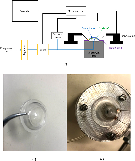
Figure 8. (a) (Top) The equipment used to test the behaviour of contact lenses on a PDMS eye. (b) (Bottom left) The PDMS eye that was mounted to the testing block. (c) (Bottom right) The assembled testing block. The PDMS eye is installed on the testing block and a lens with a 4.7 mm hole is placed on top. On the right of the image, the probes can be seen connected to the pads of the lens. The compressed air inlet tube is visible on the left of the image.
Download figure:
Standard image High-resolution imageAs mentioned above, the use of a model eye removes the effect of differently sized porcine eyes on the measurements. In addition, this apparatus included an acrylic base to which the lens samples could be adhered. Figure 8(c) shows a picture of this configuration. This apparatus ensured that the positioning of the lens relative to the eye was identical from test-to-test. Additionally, for these tests, the probe stations were connected to the lens on the pads, which were directly fixed to the acrylic base mentioned prior. This ensures that the contact between the probe station and the lens is consistent throughout the entire test period. Movement of the lens relative to the probe has a potential to change to resistance at the contact. This effect may have been present for the porcine eye tests but was mitigated for this test. As in the porcine eye tests, the lenses without holes were tested first. Afterwards, a 2.7 mm punch was used to create a 2.7 mm hole and the lens was tested a second time. Following this test, a 4.7 mm punch was used, and the lens was tested a third time. Compressed air was used to control the 'IOP' of the PDMS eye. A solenoid valve connected to a microcontroller was used to turn the pressure on and off every 10 s. Two cycles of testing were used, to check for repeatability. In the first cycle, the pressure was increased by approximately 10 mm Hg every 2 min, by manually adjusting a knob on the pressure regulator. After a pressure of approximately 40 mm Hg was reached, the pressure was decreased to about 20 mm Hg then the pressure was increased by 10 mm Hg every 1 min until 40 mm Hg was reached.
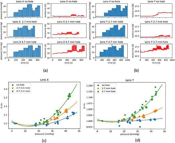
The results of this test can be seen in figure 9. Figures 9(a) and (b) shows how the pressure and resistance of the lenses vary with time. These plots show that the lenses with holes experience a larger change of resistance when exposed to the same input pressure. They also show that the lenses experience an increase in baseline resistance, which is a feature observed in other AgNW-based devices [24]. The bottom right plot of figure 9(b) shows that the resistance when the compressed air is turned off varies from 15.6 Ω at the beginning of the trial to 17.4 Ω at the end. To account for the shifting baseline, the change in resistance for a given cycle, Δr, can be found by taking the average resistance of a given cycle when the pressure is off, r0, and subtracting it from the average resistance of the cycle when the pressure is on. This can be normalized by using the relation Δr/r0. Δr/r0 for each cycle is plotted against pressure in figures 9(c) and (d). These figures show that as the diameter of the hole increases, so does sensitivity. At 40 mm Hg, lens X is 7.1% more sensitive with the 2.7 mm hole, and 17.9% more sensitive with the 4.7 mm hole. At the same pressure, lens Y is 2.7% and 8.5% more sensitive, respectively.
Figure 9. (a) (Top left) The response of lens X to pressure. (b) (Top right) The response of lens Y to pressure. (c) (Bottom left) The data from lens X is normalized and plotted with respect to pressure. (d) (Bottom right) The data from lens Y is normalized and plotted with respect to pressure.
Download figure:
Standard image High-resolution image
As pressure increases Δr/r0 increases quadratically. This is the same relationship seen in the numerical analysis discussed in section 3. However, the porcine eye results in section 4.1 show a linear relationship with pressure. A possible reason for this could be due to the simplified model used in both this section as well as in the numerical analysis. Both analyses use a simplified model of the eye, where it is modelled as a membrane with nothing inside. The real eye is more complicated, consisting of many different structures, the most predominant being the vitreous humour, a gel-like substance that fills the centre of the eye. These simplifications may be the cause of the differing observations. Anecdotally, in the PDMS eye test it was possible to observe the membrane expanding when pressure increased. It was not possible to due this for the porcine eye testing. This indicated that in the case of the PDMS eye, a greater increase in size of the eye is occurring over the pressure range investigated (0–40 mm Hg). One possibility is that the porcine eye is experiencing less strain than the PDMS eye, and at lower strain the relationship between pressure and resistance appears linear, and only appears quadratic at higher strains.
5. Conclusion
A novel contact lens sensor for detecting IOP was developed. By using a ring-shaped contact lens, rather than a traditional contact lens, an increase in the sensitivity of the device was observed. As the diameter of the inner ring increases, the sensitivity increases. Lenses with an inner ring diameter of 2.7 mm were shown to be up to 7.1% more sensitive and lenses with an inner ring diameter of 4.7 mm were shown to be up to 17.9% more sensitive. These results have implications for other strain based IOP sensors. Because removing the inner part of the contact lens increases the strain in the remaining part of the lens, other strain-based devices should be able to achieve similar increases in sensitivity by making similar modifications to the contact lens shape.
Acknowledgments
Many thanks to Angelica Campigotto for her helpful comments regarding the numerical analysis and porcine eye testing apparatus and procedure. Thanks also go to NSERC and Queen's University for their funding support.
Data availability statement
The data that support the findings of this study are available upon reasonable request from the authors.