
Abstract
In this experimental work, 6 mm thick plates of distinctive metal alloys namely AZ91C Mg alloy and AA6061 Al alloy were joined using the FSW process, and fabricated joints were investigated to apprehend the impact of convoluted interfaces and their distribution in the nugget zone and the role of intermetallic aggregates in impacting the mechanical properties of the joints. Employment of tool rotational speeds higher than 1100 rpm has fabricated AZ91C Mg–AA6061 Al joints possessing inter–infiltrating structures along with curved junctures, promoting micro-void unification (MCU) on the fractured regions owing to mechanical-related interlocking. AZ91C Mg–AA6061 Al joints have experienced tensile-related failure along the layer of intermetallic and in the regions of inter–infiltrating components nearer to the side of Al parent metal. Joints exhibiting superior strength have been attained due to the generation of intricate interfaces at the joint region, which in turn has contributed to the mechanical-based interlocking. Highest tensile strength exhibited by the joint was 242 MPa, which is nearly 78% of the strength of the parent 6061 Al alloy (310 MPa).
Export citation and abstract BibTeX RIS

Original content from this work may be used under the terms of the Creative Commons Attribution 4.0 licence. Any further distribution of this work must maintain attribution to the author(s) and the title of the work, journal citation and DOI.
1. Introduction
Alloys of Copper have the immense capability for usage in a variety of industrial sectors including marine systems, construction, transportation, encapsulating material wastages especially nuclear wastes and this usage is possible mainly because of their superior thermal and electrical conductivities, unique combination of ductility and strength, exemplary resistance to corrosion, etc [1–5]. In aerospace and automotive sectors, the reduction of weight of the components and parts are of major solicitude to enhance the fuel related economy and to curtail the emission of gases. Alloys of magnesium (Mg) possessing nearly 2/3rd the density of the alloys of aluminium (Al), was proven to be an effective and promising material for several industrial scenarios in boosting fuel savings, especially in the sectors of aerospace and automotive [1, 2]. For many decades, several alloys of Al have been employed extensively in a majority of industrial sectors owing to their modest volume of density, superior strength, appreciable intransigence against corrosion, easy degree of workability and formability, etc [3]. At the same time, as one of the exceptionally lightweight metal, alloys of Mg inherits several unique features including an easy degree of recyclability, appreciable degree of hot formability, enhanced degree of castability, superior damping-related properties, etc. Joining together the alloys of Mg and Al during the fabrication of a single hybrid structural component will lead to the enhancement of several properties and will also contribute to a reasonable amount of weight savings of the fabricated component [4–6].
To join together alloys of Al and Mg, several attempts were made using a wide variety of traditional and fusion- based welding processes including electron beam welding, laser welding, tungsten inert gas welding, induction welding, etc. However, welding of Mg-Al alloys employing these conventional joining processes is a quite complex task and attainment of joints is hindered due to obscure joint pool, larger solubility of hydrogen, higher level of oxidation, etc [7, 8]. In addition to this, the attained joints were found to possess severe flaws including cracks induced by liquation and porosity generated due to the entrapment of hydrogen in the interior portion of the joint in the interim of solidification. Moreover, the generation of several categories of IMC (intermetallic constituents) in the region of weld also deteriorates the integrity of the Mg-Al joints [9–11].
Due to these constraints and complexities faced during the welding of Mg-Al alloys using conventional joining processes, numerous experimental attempts were made, using several other distinctive joining methodologies to weld together Mg-Al alloys. These alternative joining processes include explosive welding, ultrasonic welding, friction welding, laser welding, diffusion bonding, etc [12, 13]. Even though joining together alloys of Mg and Al can be attained using these solid category joining techniques, the employment of these techniques leads to the generation of brittle-type intermetallic aggregates in the region of the interface of the Mg-Al alloy joints, thereby deteriorating the quality of the weldment. For instance, employing diffusion bonding, even though comparably superior bonding-related strength can be attained, the formation of above mentioned intermetallic type aggregates is also unavoidable and these aggregates diminish the mechanical strength and affect the time required for completing the process of bonding [14]. Likewise, when Mg-Al alloys were welded using friction welding and explosive welding techniques, the together heating up of the Mg and Al constituents will lead to the formation of brittle and hard intermetallic aggregates at the interfacing region and deteriorated the strength of the joints [15, 16]. Moreover, laser welding of Mg-Al alloys is also a strenuous task, because of the hefty differences in their metallurgical and physical relevant properties including thermal relevant conductivity, melting temperature, thermal- based expansion, crystal arrangement, etc [17].
Friction stir welding (FSW), categorized as one of the most energy-effective solid-state welding techniques seems to be competent enough to produce superior strength Mg-Al alloy joints when compared with that of the above-mentioned laser, explosion, ultrasonic, and other solid-state welding techniques, as when Mg-Al alloys are welded together using FSW process, the heating of these alloys occurs lower than their melting temperatures, thereby various flaws associated with solidification are avoided [18]. It is a proven fact that joining of Mg-Al alloys employing fusion-based welding techniques will lead to solidification of the welded metal, thereby contributing to the occurrence of brittle, hard type intermetallic aggregates including Al12Mg17, Al3Mg2, thereby diminishing the quality of weldment. Moreover, during the employment of these welding techniques, there prevails a greater level of difficulty in managing the size, distribution, and nature of the intermetallic aggregates being formed. Moreover, for attaining sound-quality joints with appreciable strength, the occurrence, size, and distribution of these intermetallic aggregates have to be controlled perfectly [19, 20]. At the same time, employment of the FSW process to join Mg-Al alloys enables greater level of control over the generation of heat and the extent of generation of the intermetallic aggregates is comparatively less, as the welding takes place at temperatures, lower than the melting temperatures of Mg and Al alloys [21].
At the same time, despite these merits, FSW process involves intensified deformation of materials at peak temperatures, thereby the fabricated weldment comprises a convoluted flow of material in their weld regions. In addition to this, during the employment of FSW to join Mg–Al alloys, alloys of Mg and Al due to the experience of peak temperatures in the nugget zone, may lead to the formation of brittle, hard type Al12Mg17 and Al3Mg2 intermetallic aggregates and may eventually lead to cracks thereby, declining the strength of the fabricated Mg–Al alloy joint [22]. To the authors' best awareness, only a few researchers have carried out experimental investigations w.r.t joining of Mg-Al alloys using the FSW process and the majority of these research investigations have been focused on the impact of process parameters like the spinning speed of the tool, rate of tool traverse, the geometry of employed tool, etc on the mechanical properties of the fabricated weldment. Research works addressing the convoluted flow of the plasticized material, relevant micro-structural transitions, and investigating the formation, distribution, role of these intermetallic aggregates in impacting the mechanical relevant properties of the dissimilar Al-Mg alloy joints have not been accomplished yet. In this paper, the FSW process was employed to weld together 6 mm thick plates of AZ91C Mg alloy and AA6061 Al alloy and this experimental work aims to understand the complicated interface of plasticized materials in the nugget zone and the distribution, role of Al12Mg17 and Al3Mg2 intermetallic aggregates in influencing the mechanical relevant properties of the fabricated Mg-Al alloy joints.
2. Material and experimental setup
In this experimental work, magnesium alloy AZ91C and aluminium alloy AA6061 rectangular plates possessing a length of 100 mm, together with a 6 mm thickness and 50 mm breadth were taken as the materials of research. The various chemical ingredients of these research materials are described in table 1. In addition to this, the tensile strength of AA6061 and AZ91C alloy was found to be 308 MPa and 281 MPa respectively.
Table 1. Various chemical constituents of the materials of research in wt%.
| Parent metal | Cu | Ni | Al | Mn | Si | Zn | Fe | Mg |
|---|---|---|---|---|---|---|---|---|
| AZ91C | 0.06 | 0.005 | 9.6 | 0.19 | 0.2 | 0.95 | 0.007 | Balance |
| Parent Metal | Mn | Ti | Fe | Mg | Si | Zn | Cu | Al |
| AA6061 | 0.08 | 0.02 | 0.44 | 0.88 | 0.72 | 0.18 | 0.35 | Balance |
The entire set of Mg-Al joints were fabricated using an FSW machine (of semi-automated nature) housed with a 415 × 810 mm work table and the table can be traversed along the 3 distinctive axes, including 405 mm in horizontal and vertical directions, 520 mm in the longitudinal direction and the photograph of this FSW machine is displayed in the figure 1(a). Flat plates of Mg and Al alloy were held together rigidly with the help of specially fabricated metal clamps, on an inimitably designed jig and fixture assembly and the schematic illustration of the arrangement of the plates is illustrated in figure 1(b).

Figure 1. (a) Photograph of the employed FSW machine (b) schematic illustration of the arrangement of the plates during FSW.
Download figure:
Standard image High-resolution imageFSW of AZ91C Mg–AA6061 flat plates were accomplished using a cylindrically tapered pin profiled tool and the photographic illustration of this tool being employed in this experiment can be seen in figure 2(a). This tool was fabricated out of molybdenum series high-speed steel being categorized M42 grade and possessed a 40 mm long outer shoulder of 20 mm diameter, followed by a 35 mm long inner shoulder of 30 mm diameter and the length of the tapered pin was 5.85 mm. The graphical representation of the dimensions of this employed tool is portayed in figure 2(b). In this experimental work, the temperature during the process of FSW was determined by using the K–category thermocouple which was being welded into the cylindrically tapered pin, almost at its mid-plane, along the axis of its rotation. Temperature-relevant data were acquired at intervals of 1.5 Hz and the response-based entities being recorded during this experiment include torque of the spindle, temperature of the tool pin, power, and force being generated axially. Schematic illustration of the temperature measurement setup being employed in this investigation is portrayed in figure 2(c). Force being generated axially was calculated by measuring the hydraulic-related pressure needed for generating the actuator movement during FSW. A drop of pressure at the spindle motor was taken into account for ascertaining the torque and the combined effect of the spinning speed of the tool and the torque of the spindle determined the power is required for this FSW of Mg-Al alloy flat plates [23].

Figure 2. (a) Photograph of the tool employed in this experiment (b) schematic illustration of the temperature measurement setup and (c) graphical representation of the dimensions of this employed tool.
Download figure:
Standard image High-resolution imageJoining of AZ91C Mg–AA6061 Al flat plates were carried out by employing various ranges of FSW parameters including the spinning speed of the tool in the range of 1100–2500 rpm, tool traverse speed ranging from 1.5 mm s−1 to 4.0 mm s−1, axial force in the range of 5–8 kN. FSW of AZ91C Mg–AA6061 flat plates was attained by placing AA6061 plates on the side of advancement and a tool offset of 1 mm and 0 mm was maintained towards the side of advancement during this experiment. The reason for placing AA6061 on the advancing side and AZ91C on the retreating side is that placing the softer metal (i.e., AZ91C) on the side of retreatment will contribute towards the enhanced flow of material in the zone of nugget and will lead to easy material transfer towards the side of advancement [24, 25]. Apart from this, keeping an offset of 1 mm towards AA6061 side is that as aluminium possesses a larger thermal expansion relevant coefficient, it could take away a higher amount of heat and will result in the even distribution of generated frictional heat to both the metals, thereby enabling successful FSW of dissimilar metal plates [26]. Another reason for welding the plates of AZ91C Mg–AA6061 alloys at an offset of 1 mm was that this 1 mm offset will enable the movement of the interface towards the side of advancement during the process of FSW [27]. The angle of tilt amidst the workpiece and tool was maintained at 1° throughout this entire experimental work.
Length of the interface region and thickness of the inter–infiltrating component (IIC) was determined on the scanned as well as on the etched cross-sections of the fabricated joints. The entire length of the interface (L) was determined by summing up the inter–infiltrating component's length and the entangled elements in the cross-section of the Mg-Al joints. Figure 3 portrays the cross–section of the macrostructure of the fabricated AZ91C Mg–AA6061 Al joints and these entangled elements are highlighted in red curved lines. The thickness of this inter–infiltrating component was determined by considering its position being parallel to the thickness of the flat plates and is indicated as 'H', as seen in figure 3. It can be noticed that this inter–infiltrating component more or less resembles the shape of the human stomach. The curvature of interfacing regions and IIC can be seen clearly in this macro-structural transaction image. The mean intermediate thickness of the stir grain size was determined for the Mg and Al alloy plates sides individually, by employing the methodology of MLI (i.e., mean linear interception). It should also be noted that, in this experimental work, the recorded values of the size of the grains for each joint were derived from the mean value of the ten distinct measurements taken on various higher magnification micrographs including 500X, 750X, etc.

Figure 3. Cross Sectional Macro-structural image of the friction stir welded AZ91C Mg–AA6061 Al joints illustrating the entangled elements and the thickness (H) of the inter–infiltrating component.
Download figure:
Standard image High-resolution image3. Research examinations
3.1. Examination of macro–structural images
Distinctive shapes of the interface region seen on the macro-structural transaction images of the AZ91C Mg–AA6061 Al joints, fabricated during the employment of distinctive process parameter combinations are portrayed in figures 4(a)–(d). In all these macro-structural transaction images, left portion represents the advancing side and the right portion represents the retreating side of the AZ91C Mg–AA6061 Al joints. It can be observed that the left portion of the joint, i.e., the side containing AA6061 Al alloy, illustrates a distinctive depiction of the weld zone when compared with that of the right portion containing the AZ91C Mg alloy. The cross section of the AZ91C Mg–AA6061 Al joint attained during the employment of the lowest value of tool rotational speed (1100 rpm) and tool traverse speed (1.5 mm s−1) is illustrated in figure 4(a).

Figure 4. Cross Sectional Macro-structural image of the friction stir welded AZ91C Mg–AA6061 Al joints attained at (a) 1100 rpm and 1.75 mm s−1 (b) 2450 rpm and 3.7 mm s−1 (c) 1850 rpm and 2.85 mm s−1.
Download figure:
Standard image High-resolution imageIt can be seen that the cross-section of this joint possesses a lean, rectilinear category of joint interface offsetting from the actual distorted joint centerline without inter–infiltrating component (IIC). The cross section of the joint illustrated in figure 4(b) possesses a peculiar impregnating structure, which occupies the almost top half of its interface region, while the lower part of this interface region possesses a slender type interface free from impregnating structures.
Figure 4(c) portrays the cross-section of the joint attained during employment of 1850 rpm and 2.85 mm s−1 and from this figure 4(c), it can be noticed that the impregnating structure is offset towards the advancing side of the interface and majority of its portion lies on the AA6061 Al alloy side. This asymmetrical characteristic appearance of the IIC must have occurred mainly due to the insertion of the employed tool at a 1 mm offset distance towards the advancing side (i.e., towards the left side of the line of joint). The pattern in which the flow of the plasticized material has taken place in this joint reveals that the variations in the employed FSW parameters have played a dominating role in shaping the interface region of the AZ91C Mg–AA6061 Al joint and have also contributed towards the formation of the impregnating structures in the weld portion.
It was a proven fact that during FSW, flow in the apex and crest portion of the plasticized material is governed by the shoulder of the employed tool and the flow in the bottom portion will be governed by the tool pin. Geometry of the employed pin-like threaded features, flute-like structures etc, was also proven to impact the mixing of plasticized material axially, during the FSW process. It was recorded by researchers that the traversing speed of the tool has a dominating role in determining the shapes of the interface, during FSW of dissimilar alloys. Moreover, Kwon et al, [28] and Charandabi et al [29] have reported that point of origin of the interface (i.e., whether the interface has to occur on retreating or on the advancing side) will be determined by the tool traverse speed and how the mixing of the plasticized material will take place in the center portion of the weld region will be decided by the rotational speed of the tool. In this present experimental investigation, the AZ91C Mg–AA6061 Al joints attained during employment of 1100 rpm and 1.5 mm s−1, exhibit the presence of a lean, rectilinear- shaped interface (as seen in figure 4(a)), without any impregnating structures in the center portion of their weld region. At the same time, the cross sections of the joints attained during employment of rotational speeds exceeding 1100 rpm and traverse speeds exceeding 1.5 mm s−1, exhibit the presence of IIC in their weld portions as observed in figures 4(b) & (c).
3.2. Examination of micro–structural images
Micro-structural image of the region of the interface of the constituents of the AZ91C Mg–AA6061 Al alloy fabricated at a tool rotational speed of 1100 rpm and tool traverse speed of 1.5 mm s−1 is illustrated in figure 5(a). In this figure 5(a), we can visualize the presence of an uninterrupted, slender, layer of intermetallic aggregates (around 2–3 μm thick) stretching over the integral length of the interface.

Figure 5. Micro-structural image of the region of the interface of the constituents of the AZ91C Mg–AA6061 Al alloy fabricated at (a) 1100 rpm and 1.5 mm s−1 (b) 2450 rpm and 3.7 mm s−1 (c) 1850 rpm and 2.85 mm s−1.
Download figure:
Standard image High-resolution imageLikewise, AZ91C Mg–AA6061 Al joints attained during the employment of other values of process parameters were also found to possess an uninterrupted layer of intermetallic in their interface regions, as illustrated in figures 5(b) & (c). Esmaeili et al [30] have already reported the presence of a similar category of an intermetallic layer at the region of the interface of Mg-Al joints attained during the FSW process.
It was already recorded by several researchers [31, 32] that the phenomenon of the flow of plasticized metal is entirely distinctive w.r.t dissimilar and similar FSW. For instance, in the friction stir welded similar metals, onion ring type architecture was usually observed in the nugget zone, but in our case of FSW of distinctive metals namely AZ91C Mg–AA6061 Al alloys, as seen in figures 5(a)–(c), an entirely intricate, interposed and vortex category micro-structure was observed. From these figures 5(a)–(c), it can also be observed that a larger stirring impact was experienced at the bottom layers and due to this stirring impact, a interposed, whirl structures can be seen at the bottom portions [33].
AZ91C Mg–AA6061 Al joints fabricated during the employment of tool rotational speeds above 1100 rpm were found to exhibit the presence of an IIC zone in their lower portion of the cross-section. Optical micrograph (at low magnification) of the thermo-mechanically impacted zone (TMIZ) of the AZ91C Mg–AA6061 Al joint attained at 1850 rpm and 2.85 mm s−1 is shown in figure 6(a).

Figure 6. Micro-structural image of the thermo–mechanically impacted zone (TMIZ) of the AZ91C Mg–AA6061 Al joint attained at 1850 rpm and 2.85 mm s−1 at various levels of magnification, namely (a) 100 X (b) 200 X and (c) 500 X.
Download figure:
Standard image High-resolution imageWe can visualize the presence of alternate dark brown and pale brown colored bands and these bands have occurred as a result of the mixing of constituents of the parent metals (namely AZ91C Mg and AA6061 Al) present on either sides of the region of the interface, during the process of FSW [34, 35]. Larger magnified images of the thermo–mechanically impacted zone (TMIZ) of this AZ91C Mg–AA6061 Al joint are also illustrated in figures 6(b) & (c).
4. Discussions on the impact of process parameters and IIC
4.1. Power and torque
The discrepancy of the process-based response variables (namely torque generated during FSW, power and the size of the grain in the nugget zone) w.r.t the speed of rotation of the tool are graphically portrayed in figures 7(a) and (b) respectively. Bars of errors seen in figures 7(a) and (b) for every speed of rotation of the tool illustrate the discrepancies in the response-based variables because of the employment of distinctive traverse speeds and the forces being generated axially during the joining of AZ91C Mg–AA6061 Al flat plates by FSW. Upward values (i.e., above the average value) of the error-related bar conform with the larger value of force generated axially or to the higher tool traverse speeds. Likewise, downward values (i.e., below the average value) of the error-related bar conform with the lower value of force generated axially or to the slower tool traverse speeds [36, 37]. By observing figure 7(a), it can be understood that the torque generated during FSW declines with the simultaneous escalation in the speed of rotation of the tool, confirming the fact that at larger speeds of rotation, the resistance towards the flow of the plasticized material constituents will be lower.

Figure 7. Graphical illustration of the discrepancies in the (a) torque being generated and (b) size of the grains in the nugget zone w.r.t. speeds of tool rotation.
Download figure:
Standard image High-resolution imageFrom this figure 7(a), it can be understood that the power generated during FSW (indicated as a triangle) escalates with the increase in the speed of rotation of the FSW tool, indirectly confirming that a larger amount of friction-based heat will be experienced by the nugget zone of the joints fabricated during employment of higher speeds of tool rotation as recorded by Galvão et al [38]. By observing figure 7(b), it can be inferred that the size of the grains in the nugget zone on both the Mg as well as Al edges, decreases progressively with the simultaneous escalation in the speeds of tool rotation. This variation in the size of the grains w.r.t. rotational speeds indirectly reveals the fact that at slower rotational speeds, the size of the grains in the nugget zone increases, due to the experience of lower values of temperature and vice versa.
4.2. Nugget zone of Mg and Al alloy
AZ91C Mg alloy side nugget SEM (scanning electron microscope) images of the AZ91C Mg–AA6061 Al joints fabricated at various rotational and traverse speeds are displayed in figures 8(a)–(c). From these figures, it can be visualized that Mg alloy side nugget has exhibited a completely recrystallized bi-modal type of grain architecture in which the mean size of the grains seems to be slightly larger than their parent metal. Figure 8(d) portrays the micro-structural image of the parent Mg metal, namely AZ91C Mg alloy. The average size of the grains of the parent Mg metal (namely AZ91C Mg alloy) was measured to be 37 μm. It can also be observed that the mean size of the grains in these regions has become slightly coarser with the escalation in the tool rotational speeds. Similar grain coarsening behaviors have been reported by several researchers including Barlas et al [39] and Babu et al [40].

Figure 8. SEM images of the Mg side nugget of the joints fabricated at (a) 1100 rpm and 1.5 mm s−1 (b) 1850 rpm and 2.85 mm s−1 (c) 2450 rpm and 3.7 mm s−1.
Download figure:
Standard image High-resolution imageFrom these observations, it can be inferred that the coarsening of the grains is impacted by the temperature of welding, which in turn depends on the rotational speed of the tool. Employing larger rotational speeds during FSW will lead to the generation of an enormous volume of frictional heat and at this higher temperature, coarsening or refinement of grains will take place in the nugget zone. The absence of the secondary phase particles in the parent Mg metal (i.e., AZ91C Mg) has also contributed to the uninterrupted coarsening of the grain structures in this zone.
AA6061 Al alloy side nugget SEM (scanning electron microscope) images of the AZ91C Mg–AA6061 Al joints fabricated at various rotational and traverse speeds are displayed in figures 9(a)–(c). Figure 9(d) portrays the micro-structural image of the parent Al metal, namely AA6061 Al alloy. Unlike the Mg alloy side nugget, the nugget side of Al alloy has exhibited enhanced refinement of grains when compared with that of its parent metal, namely AA6061 Al alloy. Average size of the grains of the parent Al metal (namely AA6061 Al alloy) was measured to be 18 μm.

Figure 9. SEM images of the Al side nugget of the joints fabricated at (a) 1100 rpm and 1.5 mm s−1 (b) 1850 rpm and 2.85 mm s−1 (c) 2450 rpm and 3.7 mm s−1.
Download figure:
Standard image High-resolution imageGrains on the Al alloy side nugget of the joints fabricated at larger speeds of rotation (greater than 1100 rpm) possesses finely refined, equal-sized, recrystallized grain architecture (as observed from figures 9(b) and (c)). on the other hand, grains on the Al alloy side nugget of the joint attained at 1100 rpm seems to have undergone recrystallization partially when compared with that of the grains of the joints fabricated at rotational speeds higher than 1100 rpm (namely at 1850 and 2450 rpm). At the same time, the grains on the Al alloy side nugget of the joint attained at 1100 rpm seem to have undergone recrystallization partially only, whereas the grains of the same joints on its opposite side (i.e., on the Mg side nugget) were found to be present completely recrystallized grain structure to some extent (as seen in figure 9(a)).
From these observations, it can be understood the response-based variables of the FSW process namely the temperature of the nugget, the power of FSW and the size of the grains are interdependent and can be associated with the speed of rotation of the tool. It can also be apprehended that the power generated during the FSW process and the temperature of the nugget escalate with the escalation in the rotational speed of the tool, with other parameters being maintained at constant values. Moreover, from figure 10(a), it can be recorded that the temperature of the nugget is dependent on the power of FSW process and it increases with the escalation in the power. From this graphical plot, it can be understood that the peak temperature experienced by the stir zone is above 580 K, the temperature at which the strengthening eutectic-based constituents, namely, Mg2Si precipitates of the 6061 Al alloy get dissolved. Likewise, at slightly larger power generated during the FSW process, the peak temperature can be observed to be 628 K, at which the Mg17Al12 brittle intermetallic constituents of the AZ91C Mg alloy gets dissolved, confirming that the fusion of the intermetallic constituents possessing eutectic composition has occurred in the interface region of the fabricated AZ91C Mg–AA6061 Al joints [20, 41].

Figure 10. Graphical illustration of (a) power generated during FSW process versus peak temperature attained and (b) peak temperature versus size of the grains in the nugget zone of the friction stir welded AZ91C Mg–AA6061 Al alloy.
Download figure:
Standard image High-resolution imageGraphical plots illustrating the variation in the size of the grains (of the nugget zone), w.r.t the power of the FSW process and the peak temperature attained during the FSW of AZ91C Mg–AA6061 Al joints is shown in figures 10(a) and (b). From these graphical plots, it can be apprehended that the size of the grains in the nugget zone and peak temperature are interdependent and similarly, there prevails a direct interrelationship amidst the power generated during FSW and the size of the grains in the nugget zone. Apart from this, it can also be observed that the grains in both the Mg and Al nugget sides have undergone major transitions w.r.t their size and architecture, even though the grain constituents of both the parent metals are entirely different. Generation of large volumes of peak temperature together with a higher amount of power generation during FSW has contributed to the enormous amount of heat input, which in turn has contributed to the transitions in the structure and size of the grains in the nugget zone of the fabricated joints [19, 42].
4.3. Variations in axial force
The force being generated axially during the FSW of the AZ91C Mg–AA6061 Al joints is another significant response-based variable and this force can also be considered as the counteraction being exerted due to the movement of the tool in the direction of joining. A 3-dimensional surface-based graph plotted amidst the speed of tool traverse, speed of tool rotation, and this axial force is illustrated as figure 11, and this graph was generated using Matlab by obtaining data from a total of 27 experimental runs.

Figure 11. 3-dimensional surface based graph plotted illustrating the variation of the axial force w.r.t. the speeds of tool traverse and speeds of tool rotation.
Download figure:
Standard image High-resolution imageFrom this graph, it can be interpreted that the axial force escalates monotonously with the concurrent increase in the tool traverse speed, with the rotational speed remaining as constant. It can also be observed that the largest value of axial force was attained during the employment of the highest tool traverse speed. In this experimental investigation, even though endeavors have not been put forward to anticipate the pattern of flow of the plasticized material through simulation-based methodologies or statistical-based analysis, the size of the inter–infiltrating components (IIC) and structure of the interfaces have been investigated.
It implies to be acceptable to assume that the axial force depends on the structure of the interfaces, as the structures of these interfaces are determined by the flow of the plasticized material. Recorded experimental data of this investigation reveal that the AZ91C Mg–AA6061 Al joints possessing interfaces with larger lengths and inter–infiltrating components with larger values of H were found to be attained during the employment of intermediate speeds of tool rotation, where the value of the axial force was found to be maximum. It was also observed that at lower speeds of tool rotation, the interfaces of the fabricated joints do not possess any inter–infiltrating structures and the AZ91C Mg–AA6061 Al joints fabricated at very larger speeds of tool rotation were found to possess surface-related cracks, due to the intermetallic type of melting of the parent metal and this which intermetallic type of melting has taken place due to the generation of larger peak temperatures, during the employment of larger speeds of tool rotation [43].
4.4. Impact of interface structures on tensile strength
The largest value of the tensile strength exhibited by the AZ91C Mg–AA6061 Al joints was 242 MPa, which is nearly 78% of the strength of the parent 6061 Al alloy (310 MPa). At the same time, the fabricated joints exhibited lower values of ductility and the formation of intermetallic phases in the region of the interface of the fabricated joints contributed to these lower values of ductility [44]. It can be understood that the tensile strength of the fabricated joints is directly dependent on the length of the interface (L), thickness of the inter–infiltrating components (H), fraction of the micro–void amalgamation area, and the thickness of the intermetallic constituents.
Deviations in the tensile strength of the AZ91C Mg–AA6061 Al joints w.r.t the ratio of the length of the interface to the thickness of the plates (L/T) is graphically demonstrated in figure 12(a). From this graph, it can be interpreted that the tensile strength of the joints has escalated expeditiously with the simultaneous increase in the L/T ratio. From this graph, it can also be inferred that there prevails a possibility that the tensile strength of the joints getting increased further with the escalation in the length and complexity of the interface.

Figure 12. Graphical illustration of the variation in the tensile strength (a) w.r.t. ratio of length of interface to thickness of the plates (L/T) (b) w.r.t. ratio of thickness of the inter–infiltrating components to thickness of the plates (H/T) and (c) w.r.t. fraction of the area of micro–void unification (MVU) and (d) w.r.t the maximum thickness of the intermetallic.
Download figure:
Standard image High-resolution imageThe deviations in the tensile strength w.r.t. thickness of the inter–infiltrating components (H) are portrayed graphically in figure 12(b). In this graph, it can be observed that with the increase in the H/T of the AZ91C Mg–AA6061 Al joints, the tensile strength of the fabricated also escalates. This is very much similar to the escalation of the tensile strength w.r.t. the increase in the L/T ratio. This enhancement in the tensile-related strength w.r.t. the increase in the ratios of L/T and H/T would have been mainly due to the mechanical based interlocking, which in turn would have promoted the micro–void unification (MVU) on the fracture regions of the tensile specimen [45]. Apart from this, escalation in the area of the fractured surface (brittle mode) has also contributed for the increase in the tensile related strength of the AZ91C Mg–AA6061 Al joints.
Deviations in the tensile strength w.r.t the maximum thickness of the intermetallic is graphically portrayed in figure 12(d). This graph illustrates that the tensile-related strength of the AZ91C Mg–AA6061 Al joints escalate with the decline in the maximum interface thickness at the region of the interface. The rationale behind this escalation in the tensile strength may be due to the minimal flaw content in the tinier intermetallic volume. From the experimental observations, it can be inferred that the speeds of tool rotation ranging from 1100 to 1850 rpm together with tool traverse speeds in the range of 1.5 to 2.85 mm/s have produced AZ91C Mg–AA6061 Al joints, in which the thickness of the intermetallic are narrower, which in turn can be associated with the enhanced tensile strength of the joints [46].
4.5. Schematics of inter–infiltrating component
It was a proven fact that in the welded joints of distinctive metals (like Al-Mg), the strength of those joints is determined by two phenomenons, namely chemical-based binding (prevailing because of the existence of intermetallic constituents) and mechanical-based interlocking (owing to the convoluted interface region of the joint) [47]. In this experimental work, the fabricated AZ91C Mg–AA6061 Al joints were found to possess a zigzag type of interface, whose entire length exceeds the thickness of the parent metals. Complicated interface region and the inter–infiltrating components of the fabricated joint have contributed for a bridging type of impact across the region of the interface of the joint and justify the fact that the thickness of these inter–infiltrating components impacts the binding strength of the joints.
It can be apprehended that the joints possessing more or less well-proportioned inter–infiltrating component (IIC) (as seen in figure 4(b)) exhibits larger values of tensile strength when compared with the joints possessing disproportioned IIC (as seen in figure 4(c)). This would be mainly due to the discrepancies in the path of fracture as seen amidst the well-proportioned and inter–infiltrating component (IIC). The illustration of the path of fracture being noticed in the welded specimen possessing well-proportioned and disproportioned IIC during the tensile-based fracture is portrayed in figures 13(a) and (b).
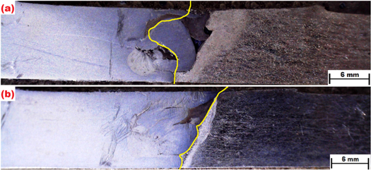
Figure 13. Schematic of the path of fracture of the AZ91C Mg–AA6061 Al joints possessing (a) well-proportioned inter–infiltrating component and (b) disproportioned inter–infiltrating component.
Download figure:
Standard image High-resolution imageWell-proportioned IIC (as seen in figure 13(a)) displays a lengthier and highly complicated, curved path of fracture when correlated with that of the disproportioned IIC (as illustrated in figure 13(b)), which displays a comparatively linear, shorter path of fracture. So, the joints possessing intricate and lengthier path of fracture demonstrates larger strength when compared with that the joints possessing linear and curtailed path of fracture.
It was recorded by researchers [21, 38, 42] that the failure of the distinctive metal joints takes place fractionally by the mechanism of MVU in the region of IIC retaining larger contents of aluminium. From these observations, it can be determined that the parameters of the FSW process that stimulate the generation of a dimensionally intricate interface are the tool rotational speeds (in the range of 1100–1850 rpm) and the tool traverse speeds (ranging from 1.5 to 2.85 mm s−1).
5. Investigations on the fractured surfaces
5.1. EDS-based analysis
Graphs being attained during the employment of the EDS (i.e., Energy dispersive based x-ray spectroscopy) based analysis of the Mg side and Al side surfaces of tensile fracture specimen attained during the employment of 1850 rpm and 2.85 mm s−1 are illustrated in figures 14(a) and (b) respectively. XRD graphs attained for the tensile-based fracture surfaces on the side of Mg alloy (figure 14(a)) exhibits zenithal peaks of magnesium-abundant Mg2Al3 metallic precipitates and teeny peaks of Al12Mg17 constituents. Likewise, XRD graphs attained for the tensile-based fracture surfaces (figure 14(b)) on the side of Al alloy exhibits lofty peaks of aluminium rich intermetallic based Al12Mg17 constituents, along with tiny peaks of Mg2Al3 metallic precipitates. From these graphs, it can be inferred that the magnitude of the peaks associated with the intermetallic constituents on the fractured surfaces seems to be tinier when compared with that of the peaks of reference.

Figure 14. EDS graphs of the tensile fracture specimen attained during the employment of 1850 rpm and 2.85 mm s−1 in the sides of (a) Mg alloy and (b) Al alloy.
Download figure:
Standard image High-resolution imageThis would have been occurred mainly because the presence of volume of these intermetallic constituents on the fractured surfaces is very much lower and they can be observed to exist as a very slim layer of about little μm thickness. Identical results were also found to be attained during the EDS analysis of the fractured surfaces of the specimen obtained during the employment of other parameter combinations. Inferences derived from analysis of the EDS graphs undeniably affirm the existence of both the categories of metallic precipitates namely Mg2Al3 and Al12Mg17 at the region of the interface of the joints including IIC [48].
5.2. SEM-based analysis
During FSW of distinctive metals, the efficiency of the joint was usually recorded lower than 100% due to the lower tensile-related strength of the joints when compared with their parent metals [49]. SEM images of the fractured surfaces of the AZ91C Mg–AA6061 Al joints fabricated during the employment of 1850 rpm and 2.85 mm s−1 illustrating the presence of intermetallic related cracks and the brittle natured facets nearer the heat impacted region are displayed in figures 15(a) and (b) respectively. From these images, it can be apprehended that these fractured surfaces have exhibited a brittle category of fracture in the majority of their region together with little ductility in their mid-portions and root edges of their fracture region, related to IIC. From these SEM images of the fractured surfaces, it can be understood that the Al side TMIZ was the weakest portion where the brittle category fracture occurred during the tensile tests, owing to the existence of brittle and hard intermetallics in this zone.

Figure 15. SEM images of the fractured surfaces of the AZ91C Mg–AA6061 Al joints illustrating (a) the presence of intermetallic related cracks (b) the brittle natured facets nearer the heat impacted region; ductile category micro–void unification (MCU) in the zones of IIC on the sides of (c) Al alloy and (d) Mg alloy.
Download figure:
Standard image High-resolution image
In figure 15(a), we can visualize the existence of trans-granular based cracking of the brittle type intermetallic constituents and wave-like patterns resembling cleavage-type facets. The structures portraying the brittle mode of fracture can be seen to fill up the majority of the fracture surfaces. Surfaces of the fractured specimen nearer the uppermost regions can be observed to exhibit some whirl-like structures, which seem to be distinctive from the remaining structures of the fractured surfaces. SEM images of the surfaces of fracture on the side of the Mg alloy (figure 15(c)) and Al alloy (figure 15(d)) seem to be present with the micro–void unification (MVU) through the entire thickness of the fractured region.
From these images, it can be apprehended that the MVU on the tensile-related fractured surfaces have taken place in the portions where constituents of aluminium have penetrated the structures which generated mechanical relevant locking. In these portions, the tensile-related failure has occurred through the aluminium alloy parent metal extending into the inter–infiltrating component (IIC) [50, 51].
6. Conclusions
An attempt was made to weld together 6mm thick plates of distinctive metal alloys namely AZ91C Mg alloy and AA6061 Al alloy using the FSW process. The main objective of this experimental work is to understand the complicated interface of plasticized materials in the nugget zone and the distribution, role of Al12Mg17 and Al3Mg2 intermetallic aggregates in influencing the mechanical relevant properties of the fabricated Mg-Al alloy joints. Experimental observations being inferred, as a part of this investigation is listed below:-
- AZ91C Mg–AA6061 Al joints fabricated at lower speeds of tool rotation (<1100 rpm) were found to be present with human stomach shaped inter–infiltrating components (IICs).
- Employment of tool rotational speeds higher than 1100 rpm have fabricated AZ91C Mg–AA6061 Al joints possessing inter–infiltrating structures along with curved junctures, promoting micro-void unification (MCU) on the fractured regions owing to mechanical-related interlocking.
- Tensile-related strength of the fabricated joints escalated with the escalation in the length of the interface, thickness of inter–infiltrating structures and fractional area of the micro-void unification (MCU) and declines with the increase in the thickness of the intermetallic structures.
- Escalation in the tensile strength of the AZ91C Mg–AA6061 Al joints with the simultaneous rise in the length and intricacy of the interface was due to the impact of the superior mechanical-related interlocking which has led to the generation of larger self-clamping impact amidst the interfaces of the joints and with the length & path of the fracture region, with the capability for the formation of MCU.
- AZ91C Mg–AA6061 Al joints exhibiting superior tensile-related strength have been attained due to the generation of an intricate interface at the joint region, which in turn have contributed to the mechanical-based interlocking.
- Tensile-related failure of the AZ91C Mg–AA6061 Al joints have taken place mainly along the layer of intermetallic (where the steady layer is visualized) and in the regions of inter–infiltrating component nearer to the side of Al parent metal.
- Employment of tool rotational speeds in the range of 1100 rpm–1850 rpm and tool traverse speeds of 1.75 mm s−1–2.85 mm s−1 has resulted in the fabrication of AZ91C Mg–AA6061 Al joints possessing intricate interface structures in their nugget zone and the generation of Al12Mg17 and Al3Mg2 intermetallic structures are unavoidable during these parameter conditions.
Data availability statement
The data cannot be made publicly available upon publication because no suitable repository exists for hosting data in this field of study. The data that support the findings of this study are available upon reasonable request from the authors.
Conflict of interest
All the authors hereby confirm that there is no conflict and competing interest between them.