
Abstract
We investigate an all-dielectric metasurface to mimic the electromagnetically induced transparency-like phenomenon in the microwave. The unit cell is comprised of two hollow split ring resonators with different parameters, which form an asymmetric structure. The proposed metasurface acquires a high transmission efficiency at 17.17 GHz, which is caused by magnetic resonance. The corresponding physical mechanism is discussed and analyzed by the distributions of the electric and magnetic fields. The experiment result of the transmission spectra is well in agreement with the simulation data. The geometric parameter of hollow split ring resonators has deep influences on transmission spectra which leads to transparency peak variation. Concurrently, the imaginary parts of the effective permittivity and permeability for the proposed metasurface are presented to explain the low-loss property. Furthermore, the transparency peak is sensitive to the surrounding environment, which exhibits potential application in refractive index sensor.
Export citation and abstract BibTeX RIS

Original content from this work may be used under the terms of the Creative Commons Attribution 4.0 licence. Any further distribution of this work must maintain attribution to the author(s) and the title of the work, journal citation and DOI.
1. Introduction
Metasurfaces are the two-dimensional structure of metamaterials with a subwavelength scale unit cell with a periodic arrangement [1–3]. These exhibit anomalous electromagnetic properties that cannot be found in natural materials, like negative refractive [4, 5], superlens [6, 7], and reversals of both the Doppler shift and Cherenkov radiation effects. On the other hand, some physics phenomenon is able to observe in metasurfaces that are difficult to realize in normal situation, for example, electromagnetically induced transparency [8, 9]. In general, electromagnetically induced transparency (EIT) is created from three levels atomic system, which has destructive interference between different energy levels [10]. Nevertheless, the strict experiment conditions, which are high-intensity laser or ultralow temperature, become large obstacle to achieve EIT phenomenon. With the emergency of metasurfaces, it provides a convenient and novelty method to realize EIT-like phenomenon under normal temperatures and pressures. In the research of metasurface, there are two approaches to mimic EIT phenomenon. One is the coupling between bright and dark modes [11], and the other is make structure of metasurfaces symmetry to break down [12]. For instance, Zhang et al [13] designed a hybrid metal-graphene EIT-like metamaterial with two orthogonally twisted split ring resonators. The EIT-like is caused by the near-field coupling between two resonators. Bagci et al [14] proposed a four-fold symmetric EIT-like metamaterial, which is generated coupled between quasi-dark and bright resonators. Du et al [15] utilized vertical cut wire as the dark mode and V-shaped cut wire as the bright mode to realize EIT-like metamaterial. Chen et al [16] demonstrated EIT metamaterial in asymmetric waveguide systems with two identical cavities in THz. In the references of EIT metasurfaces, the majority of these are primarily comprised of metal patterns and dielectric slabs [17, 18] that generates high Ohm loss because of metal structure. It is main obstacle to construct low-loss metasurface. Therefore, researcheres propose that utilizing all-dielectric designs metasurface to avoid metal loss [19, 20]. Diao et al [21] investigated an EIT-like metasurface with an asymmetric S-shaped silicon resonator in optics, which can be applied in low-loss slow-light devices.
In this paper, the all-dielectric metasurface has been modeled, fabricated, and measured to validate the EIT-like phenomenon. The two split ring resonators is slotted on the dielectric slab with different locations, which breaks down the symmetry of the unit cell. When the geometric parameters vary, the transmission spectra have a certain degree of changed. The physical mechanism of the EIT-like is analyzed by the electric and magnetic field distributions. In addition, the low-loss property of the transparency peak is verified by effective electromagnetic parameters. Finally, the proposed all-dielectric metasurface can be applied to design the refractive index sensor.
2. Design, simulation, and experiment
The unit cell is made up of 1.27 mm thick dielectric slab of Arlon 1000, and permittivity is 10.2 with the loss tangent of 0.0023. There are two hollow split ring resonators (HSRR) in the dielectric slab, as shown in figure 1(a). Due to the locations of part I and II, the unit cell becomes asymmetric structure. The detailed geometric parameters are following: L = 16 mm, l = 9 mm, p = 3 mm, d = 1.5 mm, and m = 2 mm. In the process of design and simulation, the unit cell is accomplished by CST Microwave Studio with Frequency Domain Solver. The boundary condition of the period is applied to the x- and y- directions, which satisfies to construct of the infinite structure in the simulation. The z-direction is set as open space (add) which means the electromagnetic wave is perpendicular incident to the proposed metasurface. The experiment sample is shown in figure 1(b), which is fabricated by the Laser Engraving Technique (LET). The LET is able to cut the dielectric slab and form slot of HSRR. The experiment sample is composed of 10 × 10 unit cells that the dimensions are 160 × 160 mm2. In order to measured transmission spectra, a pair of horn antennas and a vector network analyzer (Agilent E8362B) are used to acquire experiment data. Figure 1(c) is the schematic diagram of the measurement. The two horn antennas are connected with vector network analyzer, which act as emitter and receiver, respectively. The experiment sample is put into the middle of the two horn antennas to obtain the transmission coefficient.

Figure 1. (a) The schematic of the unit cell, (b) The photography of the experiment sample, (c) The diagrammatic drawing of measurement.
Download figure:
Standard image High-resolution imageTo explain the necessity of breaking symmetric, we simulate and investigate the unit cell of symmetric structure, as shown in figure 2(a). All geometric parameters of figure 2(a) are the same as that in figure 1(a), expect for the locations of part I and II. It exhibits that part I and II are put into the middle of the unit cell to construct symmetry structure. The corresponding transmission spectrum is shown in figure 2(b). It exhibits a transmission dip located at 17.40 GHz in whole frequency range where the transparency window isn't formed. This result manifests that the symmetric structure of the unit cell to design metasurface cannot achieve the EIT-like effect.

Figure 2. (a) The unit cell with the symmetric structure, (b) the transmission spectra with the symmetric structure.
Download figure:
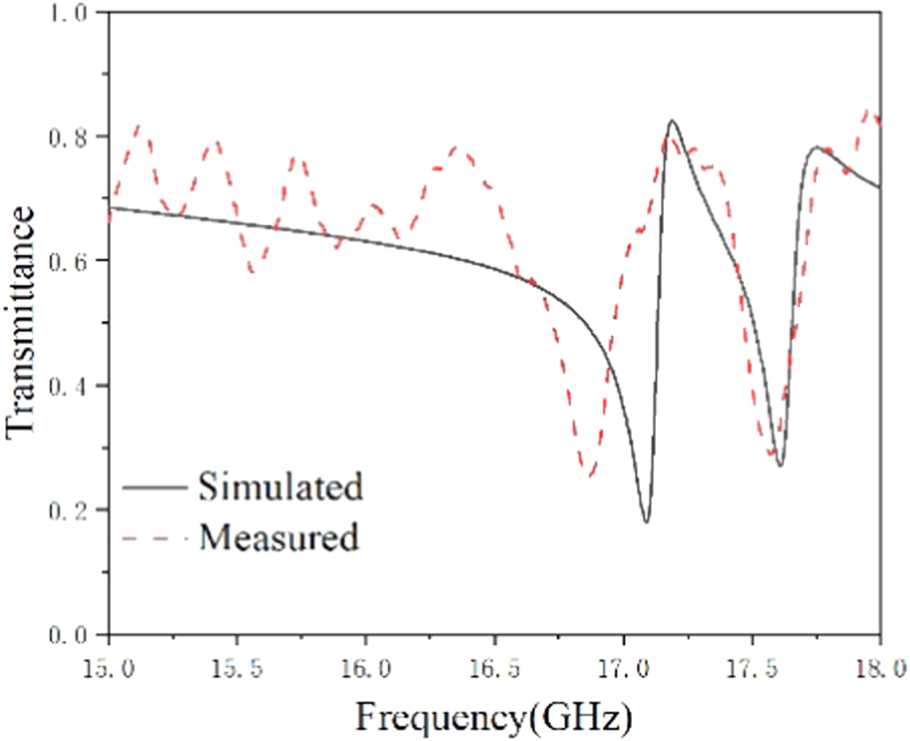
Standard image High-resolution imageWhen breaking symmetric of the dielectric slab to create the unit cell as figure 1(a), the corresponding simulation result is exhibited in figure 3. There is a transparency window between 17.07 GHz and 17.59 GHz in the solid line. The frequency of the transparency peak is 17.17 GHz, and the transmission coefficient is 0.84. It reflects that the proposed asymmetric all-dielectric metasurface is able to mimic the EIT-like phenomenon. The quality factor (Q-factor) is used to explain the property of the transparency peak, which is calculated by the resonance frequency (f) dividing the full width at half maximum. The corresponding mathematical formula is the following:  [22]. Therefore, the Q-factor of the transparency peak is 39.02. Furthermore, the dotted line is measured result of the transmission spectra in figure 3. It can observe that the transparency peak' frequency and amplitude are 17.13 GHz and 0.81, respectively. The two transmission dips locate at 16.76 GHz and 17.54 GHz, which is well agreement with the simulation result. Such a slight disparity between the two curves may primarily derive from the fabrication error of the LET, and the permittivity of the Arlon 1000 exists a little deviation between the simulation model and experiment sample.

Figure 3. The transmission spectra of the proposed metasurface with simulation and experiment results.
Download figure:
Standard image High-resolution image3. Result and discussion
To elucidate the physical mechanism of the EIT-like phenomenon in the all-dielectric metasurface, the distributions of electric and magnetic field at three specific frequencies (two transmission dips and a transparency peak) have been observed and analyzed. The magnitude scale of the electric and magnetic fields chooses same range, respectively. At 17.09 GHz, and 17.61 GHz, it observes that the power of electric field is both mainly focusing on the four corners of the two HSRRs, as shown in figures 4(a), and (c). In figure 4(b), the intensity of electric field is very weak that reflects no electric resonance at the transparency peak. At 17.17 GHz, the magnetic field is gathered on the central of the all-dielectric slab, which is enclosure by the two etched split ring resonators. Meanwhile, the intensity of the magnetic field is very strong at the transparency peak, which is shown in figure 4(e). Figure 4(d) is the distribution of the magnetic field in the first transmission dip. It shows very weak magnetic field around the etched split ring resonators, and there is some magnetic field appearing at the central of the all-dielectric slab. In the second transmission dip, figure 4(f) shows similar magnetic field distribution with figure 4(d). Comparing these three figures, the intensity of the magnetic field in transmission dips is obviously weaker than that of transparency peak. It reflects that the transparency peak is caused by the magnetic resonance in the all-dielectric slab.

Figure 4. The electric field distributions (a) 17.09 GHz, (b) 17.17 GHz, (c) 17.61 GHz, The magnetic field distribution (d) 17.09 GHz, (e) 17.17 GHz, (f) 17.61 GHz.
Download figure:
Standard image High-resolution imageThe variation of geometric parameters of HSRRs has significant effect on the transmission spectra. Here, we select two parameters of width of HSRRs (d) and the gap of HSRRs (p) to discuss. When d varies from 0.5 mm to 1.5 mm with the step of 0.5 mm, and others keep fixed. The corresponding transmission spectra are shown in figure 5(a). The transmission window locates between 15.77 GHz and 16.09 GHz since d is 0.5 mm. Meanwhile, the frequency and coefficient of transparency peak are 15.82 GHz and 0.68, respectively. Apparently, there is a resonance peak at 16.16 GHz. But it hasn't formed a transmission window that cannot be generated EIT-like. The frequency of the transparency peak has blue-shifted when the value of d is 1 mm, which is 16.54 GHz. The transmission coefficient is increased to 0.78. When d = 1.5 mm, the transparency peak locates at 17.17 GHz, and the transmission coefficient is 0.84. The above results verified that d affects frequency variation with a blue-shift phenomenon, and the transmission coefficient has increased with d enlarging. Figure 5(b) is the transmission spectra with different p. When the value of p varies from 2 mm to 4 mm with step of 1 mm, the frequencies of the transparency peak have red-shifted, which are 17.42 GHz, 17.17 GHz and 17.02 GHz. On the other hand, the transmission coefficient almost keeps unchanged. When p = 2 mm, the amplitude of the transparency peak is 0.81. When p increases to 3 mm or 4 mm, the transmission coefficient is around 0.84. It proves that p mainly affects frequency variation. Therefore, the optimized results of the d and p are 1.5 mm and 3 mm, respectively.

Figure 5. The simulation results of transmission spectra with different geometric parameters (a) d, (b) p.
Download figure:
Standard image High-resolution imageThe EIT-like metasurface have many practical application, for instance sensing, slow-light device. The refractive index sensor is one of the most useful application that can be detected the refractive index changes in the electromagnetic environment. Figure 6(a) shows the transmission spectra with refractive index (n) of the surrounding environment changing. When n varies from 1.0 to 1.3 with a step of 0.1, the transmission window moves to the low frequency, and the transmission coefficient of the transparency peak is almost unchanged. To quantify sensing ability of the proposed EIT-like metasurface, the sensitivity (S) is calculated through the frequency shift of the transparency peak divided by the refractive index unit (RIU) [23]. Figure 6(b) exhibits the frequency variation of the transparency peak with n changing. Through the data fitting, the S of the proposed metasurface is 2.8 GHz/RIU. This reflects that the proposed metasurface can realize refractive index sensing through EIT-like effect.

Figure 6. (a) The transmission spectrum with different refractive index, (b) The transparency peak frequency with different refractive index.
Download figure:
Standard image High-resolution imageThe effective medium theory is the classical analytical method to elaborate the property of low loss in metasurfaces. The effective electromagnetic parameters are calculated reflection and transmission parameters [24]. To illustrate the loss property of the proposed metasurface, the imaginary parts of permittivity (ε) and permeability (μ) of the metasurface is computed and exhibited in figure 7. The imaginary part of the effective permittivity Im (ε) reaches zero at the transparency peak and goes to the high value at the two transmission dips. The imaginary part of the effective permeability Im (μ) has two dips at 17.07 and 17.59 GHz and nearly reaches zero at 17.17 GHz. This result indicates that the proposed metasurface has low loss property at the transparency peak. Therefore, it has potential application to design low loss devices.

Figure 7. The imaginary parts of the effective permittivity (ε) and permeability (μ).
Download figure:
Standard image High-resolution image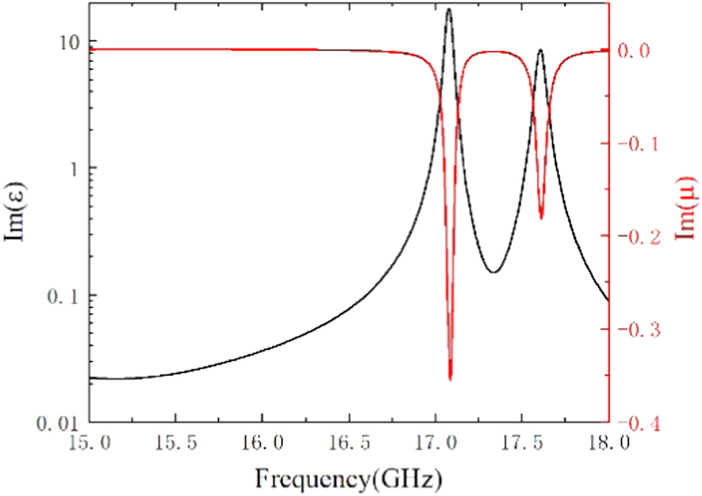
4. Conclusion
In summary, an all-dielectric EIT-like metasurface has been designed, simulated, and measured. Due to the breaking symmetric, the proposed metasurface shows high transmission efficiency at 17.17 GHz, which is sensitive to the geometric parameters of the HSRRs. The distributions of the electric and magnetic fields are used to analyze the physical mechanism of the EIT-like phenomenon, which is caused by magnetic resonance in the all-dielectric slab. By calculating effective electromagnetic parameters, the designed EIT-like metasurface exhibits low loss property at the transparency peak. Meanwhile, the proposed EIT-like metasurface exhibits good performance in the refractive index sensor.
Acknowledgments
This work was supported by the Hubei Provincial Department of Education scientific research plan guiding project (No. B2021311), and the Special Fund of Advantageous and Characteristic Disciplines (Group) of Hubei Province.
Data availability statement
The data that support the findings of this study are available upon reasonable request from the authors.