
Abstract
The utilization of natural fiber composites has been increased in replacing various parts in the automobile sector made up of synthetic fiber due to its degradability nature and environment friendliness. In this work, the naturally available Asna fiber was processed and the composites were prepared without and with steel wire mesh in various volume fractions (vf) of the fiber. In the present experimental investigation, the influence of different composite on the thermal, mechanical, and water absorption characteristics. Various properties such as tensile, flexural and impact strength were tested for the multiple composites. Subsequently, a simulation model of a car front bumper was prepared using ANSYS to test it while defining the determined properties of the composites. The test results showed that when vf was increased from 0.4 to 0.5%, the tensile and flexural were decreased by 0.72% and 59%, respectively, whereas impact strength was increased by 5.9% for the composite without wire mesh. The tensile and flexural strengths were decreased by 18.2%, whereas impact strength was increased by 1.6% for 0.5 vf of the composite when steel wire mesh was added to the composite. The investigation of composite's thermal behavior showed that when the temperature range comes within 330 °C–370 °C, the composites started decomposing. Various images were captured using Scanning Electron Microscope to investigate the fibers' dispersion in epoxy polymers and its interfacial bonding. The simulation results showed that the bumper made up of the composite with wire mesh provides a better impact strength as compared to other composites and steel.
Export citation and abstract BibTeX RIS

Original content from this work may be used under the terms of the Creative Commons Attribution 4.0 licence. Any further distribution of this work must maintain attribution to the author(s) and the title of the work, journal citation and DOI.
1. Introduction
At this moment, the thrive of utilizing natural fibers instead of synthetic fibers has been increased due to increasing environmental concerns. Animals, plants or geological processes produce natural fibers due to the presence of cellulose and protein in plant and animal fibers, respectively. It offers several advantages such as renewable and decomposable within a short span of time compared to synthetic fibers and thus exhibits an environmentally friendly characteristic. Natural fiber production results in the reduction in greenhouse gas emission and energy requirement as compared to the production of synthetic fiber such as glass fiber [1, 2]. Utilizing natural fiber provides the required property of a material to reinforcements such as recyclability, lower density, better strength, lower cost, non-toxic, required toughness, flexibility, ease to process, fatigue resistance and non-corrosive [3]. All these properties make natural fiber pose a great potential to substitute synthetic fibers to manufacture eco-friendly composites. Natural fiber composites, also known as bio-composites, can be utilized as insulation, the body of an automobile, noise-absorbing panels, furniture, building and body of aircraft and railway coaches [4]. The plant fibers are mainly classified into bast, leaf, seed, grass, core, wood pulp, root and fruit fibers, whereas the animal fibers are classified into silk, avian and animal hair fibers [5].
However, development efforts are required in natural fibers to meet the future requirement in various sectors such as vehicles and air crafts by improving thermal, mechanical, vibration, acoustic and viscoelastic properties [6]. There are various ways such as surface modification, blending, hybridization and addition of nanoparticles to further improve the properties of natural fibers to meet the requirements for future technologies [7], and out of which hybridization is the popular one. Hybridization is the process of preparing a composite utilizing two or more reinforcement materials. This method will account for all the required properties for future material. The development effort increased to meet the above mentioned properties of a material using the hybridization method as it is a suitable method to combine the properties of two or more different materials. The preparation of hybrid composite by adding wire mesh to the natural fibers enables the enhancement of properties that can be suitable for various applications such as construction and automotive applications.
Within last few years the efforts have been increased on the utilization of hybrid natural or synthetic fibers, as reviewed further. Aghchai and Khatami [8] and Khalili et al [9] have performed Charpy impact, bending, tensile, special stiffness and strength tests on the hybrid composite of glass and aluminium. The authors found that the hybrid composite has better stiffness, displacement and energy absorption than the natural fiber. The special strength and stiffness were higher for the hybrid composite as compared to natural fibers. Saktivel et al [10], Karunagaran and Rajadurai [11] and Sarlin et al [12] utilized a hybrid of fiber and stainless steel and investigated tensile, flexural, impact, shear and inter delamination properties of the composites. They found that the limit of load to crack the composite and stiffness have been increased for the hybrid composite. Also, they improved the resistance of hybrid composite from the environmental factors with the help of ethylene propylene diene monomer rubber. Singh and Brar [13] prepared leaf spring of hybrid composites using aluminium and carbon epoxy for automobile applications. The result showed that the hybrid composite has high strength and low density along with better corrosion resistance and high peel strength as compared to the single fiber. The study on the hybrid composite of glass and mild steel was performed by Lee et al [14] to test its mechanical behavior such as tensile, impact, shear and compressive strength. They observed that the hybrid composites have better mechanical properties stiffness and strength as compared to the glass fiber. Gupta et al [15] investigated the effect of hybrid composite of shape memory alloy and glass fiber on its damping ratio and stiffness. The authors compared the composite with steel and found that the damping and stiffness were enhanced for the hybrid composite as compared to steel as well as glass fiber. Qeshta et al [16] focused on the concrete beam performance by using hybrid composite of carbon, concrete and wire mesh. They found that the increase in the number of layers of wire mesh improved the energy absorption, cracking behavior and flexural strength characteristics. Wan et al [17] worked on the hybrid composite of glass fiber and wire nets to understand its impact behavior. They showed an increase in the threshold of perforation velocity and energy absorption ability of the hybrid fiber. The abovementioned works are mainly focused on the utilization of synthetic fiber, and works focusing on natural fibers are discussed ahead. Krishnasamy et al [6] and Krishnasamy et al [18] investigated the mechanical properties (such as interlaminar, impact, flexural and tensile) of hybrid composites consist of natural fiber-like jute and wire mesh with epoxy resin. They have changed the orientation of mesh and found the best mechanical properties for 45° oriented wire mesh composite. Loganathan et al [19] also focused on the hybrid composite of natural fiber i.e. banana fiber and steel wire mesh and examined the characteristics of vibration and mechanical. This led to an increase in the tensile and flexural strength of the hybrid composites as compared to the banana fiber.
Asna Fibre are not mostly involved in the fabrication of composite materials, since it is natural and is biologically degradable, the involvement of Asna fiber would reduce the exposure of pollutants into the atmosphere. So from the vast literature study underwent, the usage of Asna fiber composite would place itself as a replacement for plastic or any other material used in many other applications. Based on the gap identified and knowledge from the literature in the present work, hybrid composites utilizing natural fiber. Asna fiber is one of the common natural fibers found in Asna tree with elliptical shaped leaves at the twigs' end, known for its strength durability. This species is commonly found in the deciduous forest of India, Thailand, Vietnam, Cambodia, Laos, Bangladesh and Nepal [20], thus it is of interest.
In the present work, hybrid composite was prepared using Asna fibers and steel wire mesh to investigate the effect of fiber dimensions, fiber volume fraction of 0.4 and 0.5, and alkaline treatment of fibers on the mechanical, thermal, and water absorption characteristics of the composites. The natural fiber was processed and the reinforced fibers were made like long shaped fibers. Subsequently, the hybrid fibers were tested for mechanical properties such as flexural, tensile, and impact strength.
2. Specimen farication and experimental set-up
2.1. Materials
In this work, Bisphenol A diglycidyl ether (BADGE) was used as a matrix, which is a transparent and flexible resin. A colourless organic compound i.e. Triethylenetetramine (also called trientine) was used as hardener. A homogeneous mixture of 1% (by volume) trentine and 99% BADGE was prepared. Long fibrous strands were extracted from the Asna tree. These strands contain water vapor which need to be removed by drying it for seven days under sunlight. The natural fiber is hydrophilic and thus it is required to change its nature to hydrophobic via chemical treatment such as alkaline treatment. This treatment is the removal of hydrogen bond from the natural fiber in which the fiber is soaked in 2% NaOH solution at room temperature for an hour. Finally, the fibers were thoroughly washed with distilled water and allowed them to dry for 3 weeks in sunlight.
2.2. Methods of processing
Initially, the mould of 300 mm length, 300 mm width and 3 mm height was prepared and cleaned thoroughly with solution of thinner and kept to dry [20–24]. Afterwards, a definite quantity of fibers were organized in the above-prepared mould while placing steel mesh at the height of 1.5 mm, as shown in figure 1. Then, the thorough mixture of 90% epoxy and 10% hardener was obtained by using mechanical stirrer and poured slowly on the fibers' mat. This layer of epoxy-hardener was allowed to soak by the fibers' mat, which is necessary to remove air-bubbles and it was distributed uniformly over the mat by using roller. For curing purpose, the mould was kept at room temperature and pressurized under 50 bar for a day, and laminate was ready [21–24]. Further, the laminate was kept in the air for a day to cure it and preparing fiber reinforced composites.
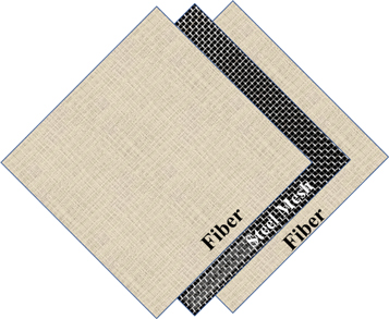
Figure 1. Schematic of fiber and steel mesh orientations in hybrid composite.
Download figure:
Standard image High-resolution image2.3. Characterisation
After preparing the composite, it is required to determine characteristics such as tensile, flexural, thermal and hydrophilic of the material. Regarding this, mechanical testing, thermal analysis and water absorption testing were performed on the composite, as discussed in the following sub-sections.
2.3.1. Mechanical testing
Initially, as per ASTM: D3039, samples of dimension  were prepared for tensile testing purpose. A universal testing machine with 2 mm min−1 cross head speed was utilised for tensile test. Also, as per ASTM: D790, samples of dimension
  were prepared for flexural testing purpose with 1 mm min−1 cross head speed, as shown in figure 2. Lastly, as per ASTM: D246, samples of dimension
  were prepared for impact testing purpose using Izod impact testing machine. The test results were the average of 5 to 3 specimens have to be prepared for testing but availability and dependency of the material available is very much intermittent so 3 specimens have been prepared and tested for mechanical analysis
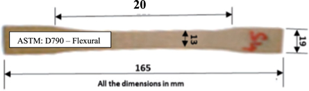
Figure 2. Flexural test sample.
Download figure:
Standard image High-resolution image2.3.2. Thermal analysis
The composite material can be exposed to the heat during their application. Thus, it is important to perform thermal analysis on the composite for the better understanding of heat impact on the composite. Regarding this, thermogravimetric (TG) analysis were used in the present investigation for thermal analysis using STA 409 PL Luxx instrument. In which, a mass of the sample is measured while varying the sample temperature to provide information about various physical phenomena such as desorption, adsorption, absorption and phase transition and about chemical phenomena such as solid-gas reactions, thermal decomposition and chemisorption [25–30]. Various samples of 10 mg were kept on the platinum pan where temperature was increased from 30 °C to 550 °C. The TGA analysis provided the onset of degradation and residue mass.
2.3.3. Water absorption test
As per ASTM: D570, circular disc samples of 50 mm diameter were prepared for water absorption testing purpose. The samples were placed in an oven maintaining 50 °C and weighed after cooling of it at room temperature. It was then dipped into the water for various durations at room temperature. The immersed sample was taken out from the water after a desired number of days and wiped with clean dry cloth to remove excess water. The geometrical dimension and mass of the sample was recorded instantly. The similar process was performed after 1, 2, 3, 4, 7, 8, 9, 10, 15, 20, 25, 30, 35, 40, 45 days of water immersion till the sample mass reached to a constant level. The mass difference of sample after water immersion and initial weight is defined as its moisture absorption capacity.
2.3.4. Scanning electron microscope analysis
Scanning electron microscope (SEM) is a feasible equipment to investigate the composite surface after each test. In this work, Zeiss Supra 55 with 3 kV accelerator voltage was utilized to capture SEM images for fibers dispersion in hybrid composite after every test and fiber and matrix interface bond. After flexural and tensile test of the composites, the images of fractured surface of fiber were captured. A small sample of the fractured surface was coated with gold vanadium to avoid charging.
3. Results and discussion
3.1. Mechanical properties
The prepared specimen of the reinforced composites without and with steel mesh were tested for tensile strength. Figure 3 shows the comparison of tensile testing trend for 0.4 volume fraction ( ) composite without and with steel mesh. It can be clearly observed that the tensile strength required for the composite having wire mesh is lower as compared to the composite without wire mesh for the same percentage of strain. However, fracture point is same for both the composites, i.e. one with wire mesh and another without wire mesh, for 0.4
  composite.

Figure 3. Comparison of tensile stress curve of 0.4 volume fraction composite for without and with steel mesh.
Download figure:
Standard image High-resolution imageThe variation of tensile strength ( ) for different ratio of Asna fibers and epoxy as well as without and with steel mesh is shown in figure 4. It is to be noticed that the
  was slightly decrease with an increase in the
  of fiber and epoxy without steel mesh. This can be due to the reason that blending of epoxy and fiber gets insufficient when fiber volume increased [3]. The
  decreased from 13.4 MPa to 11.86 MPa for 0.4
  when wire mesh was introduced in the composite [31–35]. The
  decreased from 13.1 MPa to 12.5 MPa for 0.4
  when wire mesh was introduced in the composite. With an addition of a steel mesh, the
  was decreased by 11.2% as compared to without steel mesh for 0.4
  of fiber, whereas
  was decreased by 2.5% as compared to without steel mesh for 0.5
  of fiber. However, the
  was increased with an increase in the
  of the fiber in the composite. The specimens with wire mesh has more tensile stress withstanding capacity when compared to the remaining specimens this is because of the involvement of the strength and its distribution over the composite. The steel wire mesh have high strength and was more efficiency than all other wire mesh composites and thus support more tensile strain withstanding ability. When conclusively stating the tensile stress values of composites involving steel wire has more efficacy than the composites without steel wire mesh.

Figure 4. Variation of tensile strength with fiber volume fraction for without and with steel mesh.
Download figure:
Standard image High-resolution imageThe prepared specimen of the reinforced composites without and with steel mesh were tested for flexural strength. The variation of flexural strength ( ) for different ratio of Asna fibers and epoxy as well as without and with steel mesh is shown in figure 5. It is to be noticed that the
  was decreased with an increase in the
  of fiber with epoxy without steel mesh. The
  decreased from 67.8 MPa to 46.5 MPa for 0.4
  when wire mesh was introduced in the composite. With an addition of a steel mesh, the
  was decreased by 44% as compared to without steel mesh for 0.4 [36–41].
  of fiber. The
  decreased from 28.7 MPa to 23.8 MPa for 0.4
  when wire mesh was introduced in the composite. With an addition of a steel mesh, the
  was decreased by 17.9% as compared to without steel mesh for 0.5
  of fiber. As explained for tensile ability of the specimen, the specimen with steel wire mesh involves more flexural strength than the specimen without steel wire mesh. Conclusively stating that the involvement of steel wire mesh reinforcement improves the mechanical ability of the composite.

Figure 5. Variation of flexural strength with fiber volume fraction for without and with steel mesh.
Download figure:
Standard image High-resolution imageThe prepared specimen of the reinforced composites without and with steel mesh were tested for impact strength. The variation of impact strength  for different ratio of Asna fibers and epoxy as well as without and with steel mesh is shown in figure 6. It is to be noticed that the impact strength was increased with an increase in the
  of fiber with epoxy without steel mesh. Also, the similar trend was observed for the hybrid composite, which consisted of wire mesh. It clearly showed that the absorbing capacity of composite increased with an increase in the volume fraction of fiber with epoxy, which further significantly increased with addition of a wire mesh in it. The
  increased from 12.6 MPa to 13.1 MPa for 0.4
  when wire mesh was introduced in the composite. With an addition of a steel mesh, the
  was increased by 4% as compared to without steel mesh for 0.4
  of fiber. The
  increased from 13.2 MPa to 13.4 MPa for 0.5
  when wire mesh was introduced in the composite. With an addition of a steel mesh, the
  was increased by 1.6% as compared to without steel mesh for 0.5
  of fiber.
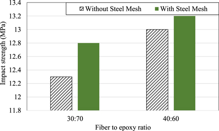
Figure 6. Variation of impact strength with fiber volume fraction for without and with steel mesh.
Download figure:
Standard image High-resolution image3.2. Thermal analysis
Figures 7 and 8 shows the thermogravimetric analysis of the composite with or without wire mesh for 0.4  of fiber, respectively. Also, figures 9 and 10 show the thermogravimetric analysis of the composite with or without wire mesh for 0.5
  of fiber, respectively. It can be clearly observed from the figure that mass the composites with and without steel mesh decreased with an increase in the temperature. This trend showed the multistage decomposition of the composite with and without wire mesh. The onset temperatures for composites without and with steel mesh were 333 °C and 332 °C, respectively for 0.5
  of the natural fiber, whereas for 0.52
  onset temperatures for composites without and with steel mesh were 338 °C and 332 °C, respectively [42–44]. The first peak of weight derivative occurred at 358 °C and 324 °C for composites without and with steel mesh, respectively for 0.4
  of the fiber, whereas for 0.5
  it occurred at 351 °C and 358 °C for composites without and with steel mesh, respectively. The mass of the composites decreased corresponding to the onset temperature, which is due to the decomposition of hemicelluloses and cellulose of fiber. The composites are thermally stable and can be used up to the onset temperature loss associated with evaporation of moisture present in the fiber. The second peak at 462 °C and 402 °C for composites without and with steel mesh for 0.4
  respectively. Moreover, the second peak for 0.5
  occurred at 506 °C and 434 °C for composites without and with steel mesh, respectively. This peak occurred because of fiber degradation due to the breakage of chemical bonds. Mass losses corresponding to these temperature intervals are observed in the curves. Also, the completion temperatures for composites with and without steel mesh are 577 °C and 572 °C for 0.5
  and 595 °C and 567 °C for 0.4
  respectively. Above these temperature residue mass can be observed constant.
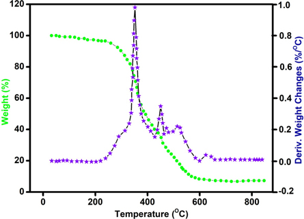
Figure 7. Thermogravimetric analysis of the composite having 30 volume fraction of Asna without steel mesh.
Download figure:
Standard image High-resolution image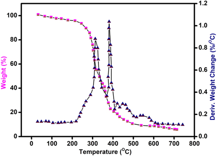
Figure 8. Thermogravimetric analysis of the composite having 30 volume fraction of Asna with steel mesh.
Download figure:
Standard image High-resolution image
Figure 9. Thermogravimetric analysis of the composite having 40 volume fraction of Asna without steel mesh.
Download figure:
Standard image High-resolution image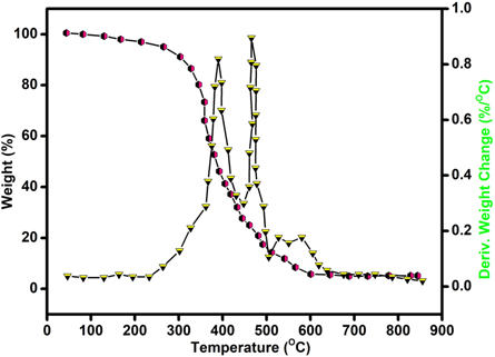
Figure 10. Thermogravimetric analysis of the composite having 40 volume fraction of with Asna fibre steel mesh.
Download figure:
Standard image High-resolution image3.3. SEM analysis
In this SEM study, only various volume fractions of Asna fiber with epoxy has been considered. Figure 11 shows the SEM images for 0.4 and 0.5 volume fractions of Asna fiber after the flexural test. It can be observed that the void spaces get reduced with an increase in the  from 0.4 to 0.5, which reflected in the adhesion and bonding between the epoxy and fiber and thus improved mechanical properties. It can be observed from the figure that due to the arrangement of the fiber, it got broken and came out from the epoxy. This is the reason behind decreasing the mechanical properties, whereas energy dissipation got improved and hence impacted strength increase. Figures 12 and 13 show the magnified views of epoxy and breaking of single fiber for 0.5 and 0.4
  during the tensile test, respectively. It can be clearly observed that scattering of fiber is more for 0.5
  as compared to 0.4
  The fibers were detached from the epoxy surface due to lesser bonding with interface bond. Figures 10 and 11 show the magnified views of epoxy and breaking of single fiber for 0.5 and 0.4
  during the tensile test, respectively. Figures 14 and 15 show the SEM images of composite having 0.5 and 0.4
  of Asna fiber for impact test, respectively. It can be clearly seen that the interfacial adhesion between the fiber and epoxy is slightly weak as a result the fibers of Asna were pull out during the impact test. This adhesion resulted in the composite capacity to bear load and provided higher stiffness and strength as well as bending resistance inner stress.

Figure 11. SEM images of flexural fracture surface for composite having Asna fiber in (a) 0.5 (500×) and (b) 0.4 (500×) volume fractions.
Download figure:
Standard image High-resolution image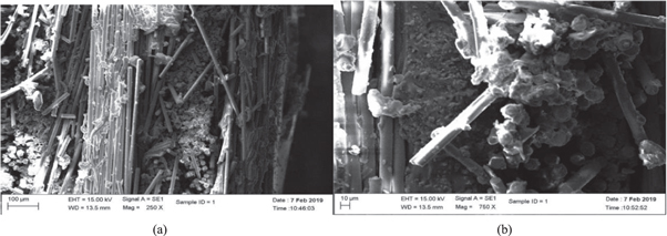
Figure 12. SEM images of tensile-ruptured Asna fiber for 0.5 volume fraction (a) thin, d = 0.04 mm and (b) thicker, d = 0.2 mm.
Download figure:
Standard image High-resolution image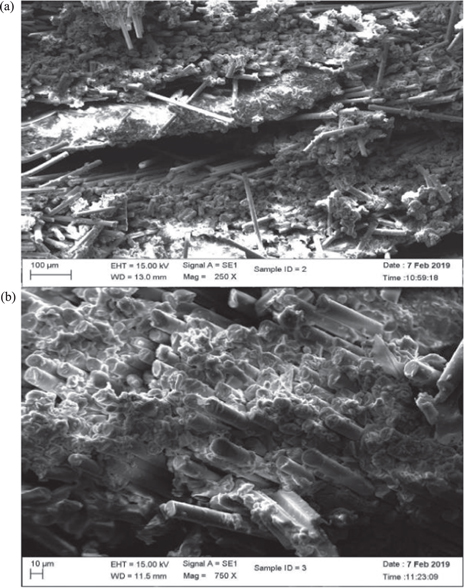
Figure 13. SEM images of tensile-ruptured Asna fiber for 0.4 volume fraction (a) thin, d = 0.04 mm and (b) thicker, d = 0.2 mm.
Download figure:
Standard image High-resolution image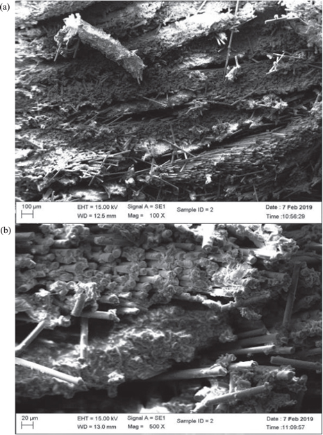
Figure 14. SEM images of impact test surface for composite having 0.5 volume fraction of Asna fiber having different resolution of (a) 200 μm and (b) 20 μm.
Download figure:
Standard image High-resolution image
Figure 15. CAD model of car front bumper.
Download figure:
Standard image High-resolution image3.4. Simulation of car bumper
After understanding of properties of the Asna fiber and its composite without and with wire mesh, it becomes important to check its application in automobile such as bumpers. The car front bumper is used to protect radiator and engine by absorbing the collision energy. In general, aluminium or steel were used for these bumpers. However, with the introduction of natural fiber composite, nowadays, it has been made up of the composite due to its high capacity to absorb collision energy and degradability.
In the present investigation, a CAD model of a bumper of a car has been designed in Solidworks and converted into standard igs format. The CAD model was imported into the Static Structural Analysis tool of the ANSYS software for simulation purpose, as shown in figure 16. It is a tool to analyse the material's ability to bear the maximum load in static condition. The CAD model was transformed into mesh domain using ANSYS Mesh tool, as shown in figure 17. The determined properties of composite without and with wire mesh were implemented for material properties. The next step was to provide boundary condition to the model by putting fixed points, location and magnitude of force. A quantum of properties such as deformation, stress and strain energy were tested under the influence of steady load.

Figure 16. Mesh domain of car front bumper.
Download figure:
Standard image High-resolution image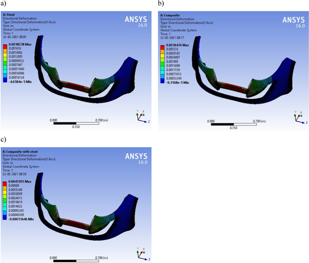
Figure 17. Deformation of car front bumper for (a) steel, (b) composite without wire mesh and (c) composite with wire mesh.
Download figure:
Standard image High-resolution imageFigure 18 shows the deformation of the bumper when a force applied on it for various types of material such as Steel, the composite without steel mesh and the composite with steel mesh. It can be clearly seen that the composite with steel mesh has more deformation as compared to other types of material. It can be evident from the tensile strength where for the same load strain in higher for the composite with steel mesh.
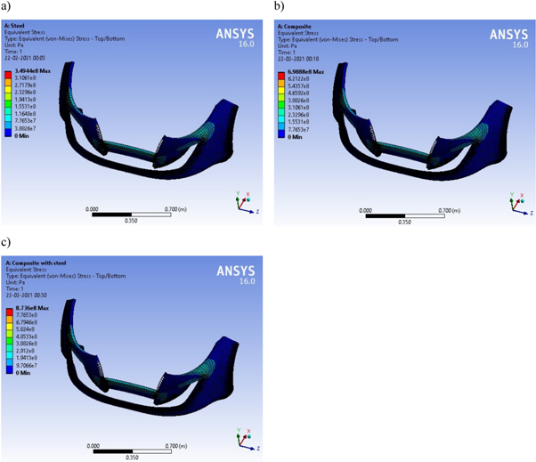
Figure 18. Stress variation on car front bumper for (a) steel, (b) composite without wire mesh and (c) composite with wire mesh.
Download figure:
Standard image High-resolution imageFigure 19 shows the stress on the bumper when a force applied on it for various types of material such as Steel, the composite without steel mesh and the composite with steel mesh. The stress is highest for the Asnafiber with steel wire mesh composite.
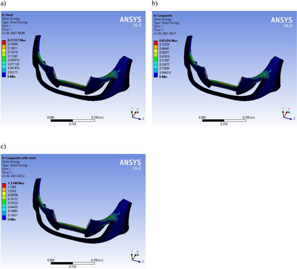
Figure 19. Strain energy variation on car front bumper for (a) steel, (b) composite without wire mesh and (c) composite with wire mesh.
Download figure:
Standard image High-resolution image
4. Conclusions
In the present experimental investigation, the influence of various composites on the thermal, mechanical, and water absorption characteristics. Various properties such as tensile, flexural and impact strength were tested for the various composites. Subsequently, a simulation model of the car front bumper was prepared using ANSYS to test while defining the determined properties of the composites. The test results showed that when vf was increased from 0.4 to 0.5%, the tensile and flexural were decreased by 0.72% and 59%, respectively, whereas impact strength was increased by 5.9% for the composite without wire mesh. The tensile and flexural strengths were decreased by 18.2%, whereas impact strength was increased by 1.6% for 0.5 vf of the composite when steel wire mesh was added. The thermal behavior of the composites being investigated in an inert atmosphere revealed that the composites decomposed within the temperature range of 330 °C–340 °C. The dispersion of fibers in epoxy polymers and their interfacial bonding were also investigated using Scanning Electron Microscope images. It showed that the composite got broken and came out from the epoxy. This is the reason behind decreasing the mechanical properties, whereas energy dissipation got improved and hence impacted strength increase. Moreover, the simulation results showed deformation on the bumper made up of steel, the composite and the composite with steel wire mesh were 1.8 mm, 3.6 mm and 4.5 mm, respectively. The strain energy on the bumper was highest for the composite with steel wire mesh compared to other materials. The strain energy was increased from 0.21 J to 0.85 J and to 1.13 J when steel material was replaced with the composite and with composite with wire mesh, respectively. As a result, the bumper made up of the composite with wire mesh provides a better impact strength than other composites and steel.
Achnowledgment
Acknowledgment: The authors extend their appreciation to the Deanship of Scientific Research at King Khalid University, Saudi Arabia for funding this work through Research Group Program under Grant No: R.G.P. 2/133/43. The authors would also like to thank Karpagam College of Engineering and Indian Institute of Technology Madras for helping this work in conducting experiments and utilizing various equipments.
Data availability statement
The data that support the findings of this study are available upon reasonable request from the authors.