
Abstract
To evaluate the Thomson effect on the temperature increase in Ge2Sb2Te5 (GST)-based phase-change random access memory (PCRAM), we created new dimensionless numbers based on Buckingham's П theorem. The influence of the Thomson effect on the temperature increase depends on the dominant factor of electrical resistance in a PCRAM cell. When the effect is dominated by the volumetric resistance of the phase-change material 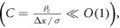 the dimensionless evaluation number is
  where ρc is the contact resistance, Δx is the thickness of PCM, σ and k are the electrical and thermal conductivities, μT is the Thomson coefficient, and Δϕ is the voltage. When the contact resistance cannot be ignored, the evaluation number is B/(1 + C). The characteristics of hexagonal-type crystalline GST in a PCRAM cell were numerically investigated using the defined dimensionless parameters. Although the contact resistance of GST exceeded the volumetric resistance across the temperature range, the ratio of contact resistance to the whole resistance reduced with increasing temperature. Moreover, increasing the temperature of GST enhanced the influence of the Thomson effect on the temperature distribution. At high temperatures, the Thomson effect suppressed the temperature increase by approximately 10%–20%.
Export citation and abstract BibTeX RIS

Original content from this work may be used under the terms of the Creative Commons Attribution 4.0 licence. Any further distribution of this work must maintain attribution to the author(s) and the title of the work, journal citation and DOI.
1. Introduction
Phase-change materials (PCMs) are characterized by largely contrasting physical properties, such as electrical resistance and optical reflectance, between their amorphous and crystalline phases. The large electrical-resistance contrast between the highly resistive amorphous and lowly resistive crystalline phases of PCM has been exploited in non-volatile memory such as phase-change random access memory (PCRAM) [1, 2]. In PCRAM, an electrical pulse induces Joule heating, enabling data writing. In the amorphization process, a short, high-intensity pulse heats the PCM to above its melting point, whereas in the crystallization process, a relatively long and intermediate-intensity pulse heats the PCM to above its crystallization temperature [1, 2]. In general, amorphization requires more energy than crystallization, so the power consumption of PCRAM operation is dominated by the amorphization process.
Ge–Sb–Te (GST) compounds have been widely studied as practical PCMs. GST shows fast resistive switching and large resistance contrast, which enhances the reliability of data reading. The main concern with GST compounds is the high power consumption originating from the low resistance of the crystalline phase and the high melting point (690 °C) [3], which requires a large current for Joule heating [4]. To reduce the power consumption of operating a GST-based PCRAM, many research groups have proposed new PCM replacements of GST [5–13] or have optimized the device structures to enhance their thermal efficiency [14–17]. Enhancing the thermal efficiency is especially important for reducing the power consumption in PCRAM because only 1% of the generated heat is invested in the phase change of PCM; most of the energy is lost during the operation [18]. As a general strategy, increasing the cell resistance can enhance the efficiency of Joule heating [8, 19, 20], but given the measurement limit on reading the cell resistance of PCRAM [21], other ways of reducing the power consumption are expected. Some recent studies have focused on the thermoelectric effect for lowering the power consumption [22–24]. This heating effect originates from the thermoelectric properties of the materials in the memory cell, including the PCM and electrode metal.
The thermal efficiency is mainly contributed by two thermoelectric effects: Peltier heating and Thomson heating. Their contributions depend on the current direction [25]. When the current flows in the positive direction (top to bottom electrode), these effects enhance the thermal efficiency [25], but when the current flow is negative (bottom to top electrode), they lower the thermal efficiency [25]. In this study, we focus on the thermoelectric effects in the positive direction to understand the mechanism of enhancing the thermal efficiency. The Peltier heating qPeltier is induced by the difference between the Seebeck coefficients of the PCM and the contact electrode metal, ∆S [24]. The qPeltier is expressed as

where T and j indicate the temperature and current density, respectively. As PCM generally shows p-type semiconductor characteristics and the S of metal is negligibly small, ∆S is usually a positive quantity. Therefore, Peltier heating should enhance the thermal efficiency in the positive direction. Meanwhile, the Thomson heating, qThomson, operates through the gradient of S with respect to temperature T. qThomson is expressed as

where the Thomson coefficient μT [24] is defined as T∂S/∂T. Therefore, the sign of μT is determined by the temperature dependency of S in the PCM. μT is known to be positive in amorphous GST, but the determination of μT in crystalline GST is complex because ∂S/∂T is negative in the face-centered cubic phase but positive in the hexagonal phase [24]. Therefore, in contrast to the Peltier effect, the Thomson effect to the thermal efficiency during the amorphization process is complex, but it has been pointed out that the programming current reduction due to the Thomson effect is larger than that due to the Peltier effect in devices with small electrode contact area, for instance, below 100 nm × 100 nm [24].
Although the contribution of the Thomson effect to the thermal efficiency has been investigated in numerical simulations [24–26], previous numerical simulations overlooked the importance of contact resistance between the PCM and electrode, which exerts a considerable influence in highly scaled PCRAM cells [8, 27, 28]. To accurately evaluate the contribution of the Thomson effect, numerical analysis should incorporate the contact resistance. When the contact resistance is introduced, the contribution of the Thomson effect on the temperature distribution and operating energy is also changed. It means that we need to evaluate the influence of Thomson effect with contact resistance. Also, for minimizing the operating energy of PCRAM, a new PCM to replace GST must be developed. For example, as promising PCMs enabling a low operating energy, Cu2GeTe3 [5] and Cr2Ge2Te6 [8] have been proposed. Even if the Thomson coefficient is the same, its contribution to the energy efficiency and temperature distribution would be different for different PCMs due to other physical properties. Therefore, a methodology to evaluate the contribution of Thomson effect in a unified manner is necessary. For this purpose, we require a generalized rule to evaluate the Thomson effect, also considering the contact resistance.
In this study, we introduce dimensionless numbers for evaluating the contribution of the Thomson effect on the temperature increase in a PCRAM cell in a generalized form. The physical meanings of the defined dimensionless numbers are revealed in numerical simulations of the Thompson effect with contact resistance. Using the defined dimensionless numbers, we finally evaluate the characteristics of GST alloy and propose a clear generalized rule for evaluating the various causes of temperature increase in PCRAMs.
2. 2. Numerical analysis
2.1. PCRAM cell structure
Our analyses were performed on a simplified two-dimensional PCRAM cell (see figure 1). The PCM lay on a SiO2 layer enclosing a TiN heater. Tungsten (W) layers formed the top and bottom electrodes. The calculation domain was a rectangle with dimensions of 1500 nm × 450 nm (width × height). The W top electrode, PCM, SiO2 and TiN layers were 150, 100, 50, and 50 nm thick, respectively, and the TiN heater was 34 nm wide. The current flowed from the top to the bottom electrode.

Figure 1. Calculation domain of the PCRAM unit.
Download figure:
Standard image High-resolution image2.2. Governing equations
To investigate the balance between the Thomson effect and Joule heating, we simulated the following governing equations:


where ρ and cp are the density and heat capacity, t denotes time, k and σ are the thermal and electrical conductivities, respectively, and ϕ is the electric potential. The current is given by

We solved the above equations for the composed materials of the PCRAM cell. The used physical properties are shown in table 1.


2.3. Boundary conditions
At the side boundaries, an adiabatic temperature condition was imposed, and the normal gradient of the electric potential was set to zero. At the top and bottom boundaries, the electrical potential was set as

and the temperature was fixed at 298 K. The thermal boundary resistance was neglected in the present simulation. The heat flux was balanced at all boundaries between the materials:

where the subscripts a and b indicate the adjacent materials at the interface, and n is the normal unit vector to the boundary. The boundary conditions of the electrical potential at the W/PCM, PCM/SiO2, TiN/SiO2, SiO2/W, and TiN/W interfaces were set as

At the TiN/PCM interface, the contact electrical resistance was imposed as

where Δϕi is the contact electrical potential and ρc is the contact resistance.
2.4. Other calculation conditions
The physical properties of the materials in the present numerical simulation are listed in table 1. All properties were assumed at room temperature, and the crystalline and amorphous phases of GST were designated as C-GST and A-GST, respectively. In order to be consistent with the experimental results (Supplementary Information), the physical properties of the hexagonal-type crystalline GST were used as C-GST parameters. Note that we ignored the temperature dependence of thermal conductivity (k), pseudo-contact resistivity (ρc), density (ρ), and heat capacity (cp). The ρc incorporates the contact resistance into the numerical analysis. This parameter will be explained in the following section and the supplementary information.
The governing equations were discretized by the finite volume method. The spatial and temporal derivatives were discretized by the second-order linear interpolation scheme and the first-order implicit Euler scheme, respectively. The discretized algebraic equations were weakly coupled by an outer iteration of each component. At each time step, the Laplace equation for the electrical potential was solved until it converged. The calculation time step and duration time were set to 1 ns and 100 ns, respectively. A constant voltage was applied at t = 0 s and the temperature variation was evaluated at 1-ns intervals. The phenomena were evaluated at 100 ns. At this time, the system was assumed as steady state because the temperature distribution was stabilized at approximately 50 ns. The computational grid was structured and uniform. The side-length of each grid cell was 2 nm. These calculation models were incorporated into the open-source software, OpenFOAM (v1812). As the standard OpenFOAM solver cannot solve the above thermoelectric phenomena, we created a new solver based on the multi-region function of OpenFOAM.
3. Results and discussion
3.1. Definition of dimensionless numbers
3.1.1. Buckingham's Π theorem
We first classified the phenomena into two cases: (I) without contact resistance, and (II) with contact resistance. In the case without contact resistance, one can define seven independent physical variables as

where Δϕ is the applied voltage and Δx is the PCM thickness. In this system, the physical variables can be described by five independent physical units:

Applying Buckingham's П theorem, the phenomena in this system can be represented by two dimensionless numbers.
In the case with contact resistance, one can define eight independent physical variables as

These variables are described by five independent physical units as shown in equation (11). Again applying Buckingham's П theorem, the phenomena in the case of contact resistance can be described by three dimensionless numbers.
3.1.2. Dimensionless numbers without contact resistance
To non-dimensionalize the governing equations (3) and (4), we define the following dimensionless numbers:

where the asterisk indicates a dimensionless variable. Substituting expressions (13) into equations (3) and (4), the dimensionless governing equations are respectively obtained as


In these dimensionless governing equations, we define the dimensionless numbers as follows:


As predicted by Buckingham's П theorem, we could define two dimensionless numbers in this system.
To evaluate the influence of the Thomson effect on the temperature increase in PCRAM, we require another normalized temperature. Considering the thermal diffusion and Joule heating terms, the governing equation in steady state is written as

Here, the dimensionless governing equations were normalized under the following assumptions:
- The steady-state temperature is linearly distributed along the vertical direction
- The steady-state electrical potential is linearly distributed along the vertical direction
- The contact resistances except at the PCM/TiN interface are sufficiently small
Substituting equation (5) into equation (18), we obtain the following equation:

Finally, the temperature increase is given by

The dimensionless temperature can be normalized by equation (20). Taking the dimensionless temperature as  the steady-state dimensionless energy equation transforms into

As seen in this equation, the influence of the Thomson effect on the temperature variation in PCRAM can be evaluated by a single dimensionless number, B.
3.1.3. Dimensionless numbers with contact resistance
In the case with contact resistance, we must consider three dimensionless numbers as discussed in section 3.1.1 The contact resistance is non-dimensionalized as

Substituting equation (9) into equation (22), we obtain

An additional dimensionless number is defined as

Equation (23) can be physically interpreted as

We decided that contact resistance dominates the effect when C is higher than O(1) (i.e., order 1). In this case, the magnitude of the electric current is determined not by the volumetric resistance of PCM but by the contact resistance. Under this condition, the effective electrical voltage (Δϕeff) in the PCM is calculated as

The electric potential applied at the PCM–electrode interface is given by

Equation (27) is finally transformed as

The current density and temperature increase are respectively given by


Using equations (28)–(30), the dimensionless variables are defined as

Substituting equation (31) into equations (3) and (4) in steady-state, the dimensionless governing equations are given as


Finally, the equation is described in terms of the dimensionless numbers:

In the case with contact resistance, the contribution of the Thomson effect on the temperature distribution can be evaluated by the ratio of two dimensionless numbers, B/(1 + C).
3.2. Validation of defined dimensionless numbers
To validate the above-defined dimensionless numbers, we conducted numerical simulations with and without contact resistance while varying the electric potential (voltage). First, the influence of Thomson effect on the temperature increase was evaluated in the absence of contact resistance. The dimensionless number B under the different applied potentials is listed in table 2. Amorphization in C-GST was confirmed under applied voltages of 0.2–0.3 V in a preliminary numerical simulation. Therefore, the B value in this case is shown only at 0.1 and 0.5 V. In A-GST, the dimensionless number was much smaller than 1, so the Thomson effect on the temperature increase was assumed negligibly small. Conversely, in C-GST, the B approached 1 and increased with voltage.
Table 2. Dimensionless number B at different applied voltages.
| A-GST | C-GST | |
|---|---|---|
| Δϕ = 0.1 V |

|

|
| Δϕ = 0.5 V |

|

|
| Δϕ = 1.0 V |

| — |
| Δϕ = 2.0 V |

| — |
| Δϕ = 4.0 V |

| — |
To confirm the relationship between the B and temperature increase, we simulated the temperature distribution of C-GST for various B values. The Thomson coefficient was varied from 0 to 10 μT. Figure 2 shows the simulated temperature distribution at 100 ns and 0.2 V in the C-GST without contact resistance. Increasing B decreased the maximum temperature. When B exceeded O(1), the Thomson effect largely affected the temperature increase. According to the simulation results, the influence of the Thomson effect on the temperature increase can be evaluated through B, as derived in section 3.1.2.

Figure 2. Simulated temperature distribution of C-GST at 100 ns under an applied voltage of 0.2 V without contact electrical resistance: (a) without the Thomson effect (B = 0), (b) with a Thomson effect of 0.1μT ( ), (c) with a Thomson effect of 1μT (
 ), and (d) with a Thomson effect of 10μT (
 ).
).
Download figure:
Standard image High-resolution imageSecond, we validated the classification of dimensionless numbers in the case of contact resistance. Prior to the numerical simulation, we investigated the incorporation of contact resistance into the system. In classical theory, the contact resistance is calculated by dividing the contact resistivity by the contact area between the PCM and electrode. However, when the contact resistance was defined in this way, the temperature was hardly increased under the applied voltage because the contact resistance was large and blocked the current flow (Supplementary Information). In a highly scaled PCRAM cell, the device resistance was reportedly dominated by the contact resistance [8, 27, 28]. However, the device resistance calculated using the contact resistance is known to exceed the experimentally obtained device resistance because the latter is lowered by leakage current [34, 35]. Therefore, when including the contact resistance, we should also consider the leakage current. To extract the influence of contact resistance and apply it to the numerical simulation, we introduced and experimentally determined a new parameter called the pseudo-contact resistivity, ρc, which brings the contact resistance into the numerical simulation. The details are given in the Supplementary Information.
When contact resistance is present, the current flow requires a larger voltage than in the case without contact resistance. Therefore, in the numerical simulations with contact resistance, the voltage in the C-GST was set to 4.0 V. To evaluate the contribution of the Thomson effect on the temperature increase, we set four Thomson coefficients: 0, 0.1μT, 1.0μT, and 10 μT, giving dimensionless number ratios B/(1 + C) of 0, 1.37 × 10⁻¹, 1.37, and 1.37 × 101, respectively. Figure 3 shows the temperature distributions at 100 ns in the contact resistance cases with the four values of B/(1 + C). Through the parameter ratio B/(1 + C), we can estimate the contribution of the Thomson effect under the influence of contact resistance. When the ratio was smaller than O(1) (figure 3 (a) and (b)), the temperature increase was independent of the Thomson coefficient because the Thomson effect was much smaller than Joule heating. Conversely, when the ratio exceeded O(1), the Thomson effect noticeably lowered the maximum temperature (see figure 3 (d)).

Figure 3. Simulated temperature distributions in C-GST with contact electrical resistance at 100 ns under an applied voltage of 4.0 V for various dimensionless number ratios B/(1 + C): (a) 0, (b) 1.37 × 10⁻¹, (c) 1.37, and (d) 1.37 × 101.
Download figure:
Standard image High-resolution imageIn addition, the dimensionless parameters can locate the maximum temperature in the GST. Figure 4 shows the temperature distributions along the central vertical line of the C-GST for different evaluation parameters in the cases without contact resistance (panel (a)) and with contact resistance (panel (b)). The origin of the x coordinate was set at the bottom surface of the C-GST. The maximum temperature shifted downward as B or B/(1 + C) increased, reflecting an increased cooling effect by the Thomson effect in the PCM component.

Figure 4. Temperature distributions along the central vertical line of C-GST with different evaluation parameters: (a) without contact resistance at 0.2 V and (b) with contact resistance at 4.0 V.
Download figure:
Standard image High-resolution imageFigure 5 is a flowchart of the method for evaluating the contribution of the Thomson effect in PCM. The first step calculates the dimensionless number C, which determines whether the evaluation method changes. When C is much smaller than 1, the contribution of the Thomson effect on the temperature increase can be evaluated using B = μT σΔϕ/k, but when C is closer to 1, the contribution of Thomson effect can be evaluated by the ratio of dimensionless numbers, B/(1 + C). In both cases, the Thomson effect alters the temperature increase when the evaluation parameter exceeds O(1), and its contribution increases with increasing dimensionless evaluation parameter.

Figure 5. Flowchart of the method for evaluating the contribution of Thomson effect on phase- change memory.
Download figure:
Standard image High-resolution image3.3. Characterization of crystalline GST
Following the flowchart in figure 5, we evaluated the characteristics of C-GST in PCRAM; especially, the influence of the Thomson effect on the temperature increase. We first evaluated the dominant resistance factor through C. The temperature-dependent electrical conductivity and Thomson coefficient [33] were respectively determined as follows:


The temperature-dependent resistivity is positive (equation (35)), indicating metallic characteristics of C-GST[33]. That is, the temperature-elicited change in the electrical characteristics originates from a mobility change rather than a carrier-density change. As the temperature dependence of carrier density is assumed negligible in C-GST, the temperature dependence of the contact resistivity was ignored in the calculation. This assumption is based on the contact resistivity measurements of Roy et al [36] and Deshmukh et al [37], who demonstrated a near-negligible temperature dependence of the contact resistivity in both face-centered cubic and hexagonal closest packed crystalline forms of GST. The temperature dependence of C in the C-GST is shown in figure 6. The C was a decreasing function of temperature. The contact resistance exceeded the volumetric resistance of C-GST across the temperature range, but (as shown in figure 6) its contribution reduced with increasing temperature.

Figure 6. Temperature dependence of the dimensionless number C of C-GST.
Download figure:
Standard image High-resolution imageTo establish the relationship between B/(1 + C) and temperature, we must understand the relationship between the temperature change and voltage, which is roughly estimated by equation (30). We thus simulated the temperature distribution at different voltages. Figure 7 plots the maximum temperature increase versus voltage in the C-GST with contact resistance. As the approximation curve differed from that given by equation (20), it was multiplied by a constant and fitted. When weighted by 0.02, the temperature increase calculated by equation (30) well agreed with the simulated curve. The analytical solution (equation (30)) was derived in a one-dimensional configuration, so its results differed from the simulated results and the value of weighting factor was meaningless. This result also indicates that the temperature increase can be roughly estimated from the physical properties using the dimensionless numbers. From the temperature change versus voltage relationship, the B/(1 + C)–temperature relationship was calculated and is plotted in figure 8. In C-GST at low temperature, the Thomson effect was negligibly small because the B/(1 + C) was lower than O(1). In contrast, the B/(1 + C) exceeded 1 in the higher temperature range, and the Thomson effect in the C-GST dominated the temperature increase. As estimated from figure 4, the Thomson effect suppressed the temperature increase by approximately 10%–20% in the high-temperature range. The present study confirmed that the Thomson effect increased the operating energy in C-GST, especially in the high-temperature range.

Figure 7. Simulation result of maximum temperature difference versus voltage in the C-GST without contact resistance.
Download figure:
Standard image High-resolution image
Figure 8. Temperature dependence of B/(1 + C) in C-GST.
Download figure:
Standard image High-resolution imageIn the present study, we investigated the contribution of the Thomson effect on the thermal efficiency using dimensionless numbers. Thus far, evaluating the contribution of Thomson effect on the thermal efficiency has been difficult, because this effect depends on the relationship between the electric potential and temperature fields. Using the proposed dimensionless numbers, we can easily evaluate the contribution of Thomson effect on the temperature increase and hence understand the phenomenon.
4. Conclusions
We created new dimensionless numbers for evaluating the Thomson effect in GST-based PCRAM. Which number is appropriate depends on the contribution of the contact resistance. The main results are summarized below.
- The contribution of contact resistance was evaluated by a dimensionless number
 which indicates the ratio of contact resistance to volumetric resistance.
 - When C is small (C ≪ 1), the Thomson effect can be evaluated by the dimensionless number, B = The Thomson effect significantly changed the temperature distribution in the PCRAM cell when the dimensionless number B was larger than O(1).
- In the alternative case (C closer to or larger than 1), the Thomson effect can be evaluated by the ratio of dimensionless numbers B/(1 + C). The Thomson effect significantly changed the temperature distribution in the PCRAM unit when the ratio of dimensionless numbers B/(1 + C) was larger than O(1).
- The maximum temperature in the PCM shifted toward the TiN heater when either B or B/(1 + C) increased.
- In crystalline GST, the contact resistance exceeded the volumetric resistance of GST across the temperature range, but the ratio of contact resistance to volumetric resistance reduced at higher temperatures.
- The Thomson effect negligibly influenced the temperature distribution in crystalline GST at low temperatures, but exerted a large effect at high temperatures, affirming that the operating energy was increased by the Thomson effect in the high temperature range.
- Using the present dimensionless numbers, we can evaluate the contributions of contact resistance and Thomson effect on the temperature distribution in a PCRAM cell.


Acknowledgments
This work was supported partly by JSPS KAKENHI, Grant-in-Aid for Scientific Research (A), Grant number 21H04604, and partly by JSPS KAKENHI, Grant-in-Aid for Scientific Research (S), Grant number 21H05009. The authors thank Prof. J. Hong (Hanyang University, Korea) for help with the preparation of substrates.
Data availability statement
The data that support the findings of this study are available upon reasonable request from the authors.
Author's contributions
These authors contributed equally to the manuscript: Takuya YAMAMOTO and Shogo HATAYAMA.