

Abstract
In the current work, applying a rotating magnetic field (RMF) is an innovative approach to improve the microstructure features and creep resistance of Sn-2.0Ag-2.0Zn (SAZ) alloy. The results revealed that RMF does not change intermetallic compounds (IMCs) constituents furthermore SAZ alloy with applying a magnetic field (SAZ-B) exhibited microstructure refinement and homogeneous distribution of IMCs. Moreover, SAZ-B displayed more creep resistance (∼366%) and greater creep rupture time (∼56.4%) than those of SAZ alloy. These results have great implications in improving the alloy's performance for industrial applications.
Export citation and abstract BibTeX RIS

Original content from this work may be used under the terms of the Creative Commons Attribution 4.0 licence. Any further distribution of this work must maintain attribution to the author(s) and the title of the work, journal citation and DOI.
1. Introduction
Due to the environmental and human health problems regarding the inherent toxicity of Pb-containing solders, the use of Pb has been forbidden in the microelectronics industry, water piping, cans of food and beverage, and automotive products in the last decade [1–5]. The ban of Pb-solders use in electronic applications has been strongly promoted to conserve the environment and creating a lead-free solder (LFS) has become a critical issue [6, 7]. Indeed, the complete implementation of novel LFS involves thorough knowledge and understanding of their microstructure, mechanical, and wettability. From this motivation, scientists strive to produce novel LFS systems that are identical or superior to the conventional Pb-Sn solder alloy. Considering soldering cost, performance, reliability, and good mechanical properties among the LFS alloys, the Sn-Ag binary LFS has been recommended as an alternative for Pb-Sn eutectic solder [8–10]. Nevertheless, the presence of the coarse Ag3Sn particle contributes to the nucleation of microcracks induced by the decohesion along with the matrix, which can speed up the failure process and harms the reliability [11, 12]. To solve these drawbacks and develop LFS reliability, adding minor alloying elements is one of the potential approaches [13, 14]. Zn received plenty of attention as a commonly used alloying element because of its slowing down IMCs growth rate, Kirkendall voids creation, and whisker growth on the surface [15]. Ervina Efzan et al showed that adding 1% Zn to Sn-Ag eutectic alloy enhanced mechanical strength while maintaining an identical value of ductility. Conversely, adding Zn >1% worsens the mechanical properties [16].
Literature review revealed that doping Zn into Sn–Ag solders could hinder the growth of Ag3Sn phase [12, 17]. Also, Zn addition drastically suppressed the Cu6Sn5 and Cu3Sn IMCs, causing an enhancement of the reliability joints of LFS [18]. Witkin concluded Bi enhances the creep resistance of Sn-Ag and Sn–Ag–Cu LFS [19]. Hwang et al showed that Cu addition into Sn–Ag changes the microstructure and consequently enhances the joining properties [20]. Also, adding 8 wt% Sb to Sn–Ag alloy leads to the phase transformation AgSn ↔ AgSb because of the rest reaction of Ag-atoms with β-Sn matrix, resulting in improving the strength of solder alloys [21, 22]. Moreover, adding 2 wt% Bi to Sn-3.5Ag refined the grain size, decreased the strength, and enhanced creep resistance [23].
In the last decade, because of the pursuit of ideal LFS, several alloys' compositions have been produced. However, less attention was paid to the property's improvement using a magnetic field. The RMF characteristic is controlled by two parameters: the angular frequency and the magnetic intensity B [24, 25]. Generally, the main axis of the sample (solidification direction) and the RMF rotation axis are aligned. RMF creates an azimuthal liquid flow around the main axis of the sample recognized as the primary flow, which causes a flow parallel to the main axis of the sample identified as the secondary flow [24–26]. Luo et al studied the influence of the magnetic stirring on the microstructure features and mechanical characteristics of Mg-alloy and Al-alloy [27, 28]. Lanin et al showed that a rotating magnetic field allows different processes to work with high- efficiency [29]. Moreover, El-Daly et al showed that applying RMF improved the hardness and elastic modulus of Sn-Bi-Cu LFS [30]. In our recent work, results showed that RMF improved mechanical strength by ∼110% and ductility by ∼108% for Sn–Ag–Cu–Zn LFS [31]. Also, Yang et al demonstrated that applying RMF could affect the growth and orientation of Cu6Sn5 IMCs in the microstructure of LFS [32].
Applying RMF is an innovative approach in the LFS. pplying RMF through solidification of solders can influence the transfer of heat and solute in the melt which enhances the microstructure. Thus, using magnetic fields has become a crucial interest in various metallurgy applications, growth of crystal for obtaining both high-quality products and efficient manufacturing processes [33]. In more detail, the applied magnetic field produces a more homogeneous melt, which promotes heterogeneous nucleation of IMCs. Stirring IMCs inhibits their growth and agglomeration. Also, the uniform distribution of IMC precipitates prevents crack propagation, dislocation and improves the solder joint strength [32–34]. Furthermore, Sun et al reported that the electromagnetic stirring results in rapid IMC growth [35]. Meng et al found that applying RMF produces dendrites fragmentation, microstructure homogeneity of Pb-Sn solder alloy, and macrosegregation elimination [36]. Moreover, RMF reduced Gibbs free energy for Pb-Sn, therefore improving the nucleation rate [37].
Recently, a lot of studies indicated RMF has significant effects on the microstructures and material performances of alloys [38, 39]. Also, Çadırlı et al showed that applied RMF altered the microstructure, electrical resistivity, and tensile properties of Al-Cu-Co alloys [40]. Liotti et al studied the impact of a pulsed electromagnetic field on dendrite fragmentation in Al-Cu alloy [41]. Shevchenko et al demonstrated that the applying electromagnetic field on Ga-In alloy produced unstable primary dendrites development and promoted secondary and tertiary arms growth [42]. The impact of the magnetic field resulted in strain increasing of Al-Mg-Si alloy to 35% [43]. Au-20Sn alloy under magnetic field effect displayed strain and fracture stress 64% and 1456.7 MPa [44]. The microstructure of Sn-Zn-Bi alloy was studied under different high magnetic fields [45].
Despite the many experiments investigating the effect of applying RMF on the properties of lead-free solders, enhancement of properties of novel LFS was predicted by applying RMF. To investigate the properties of LFS and to develop novel ones, it is very crucial to unveil the interaction between the alloy elements and mechanical properties under applying RMF in LFS. Thus, a question arises: What is the effect of applying the magnetic field to Sn-2wt%Ag-2.0wt%Zn. Especially, how do you predict applying RMF improves the microstructure and creep properties of novel Sn-2wt%Ag-2.0wt%Zn LFS?
Up to now, no research had studied the effect of magnetic field on properties of Sn-2.0wt%Ag-2.0wt%Zn (SAZ) alloys. Also, creep is the most important controlling deformation mechanism to understand the overall deformation and failure behaviors of the electronic package. Hence, attempts have been made to improve the creep properties of alloys. Thus, this study aims to enhance the microstructure and creep resistance of novel SAZ LFS by applying RMF. Furthermore, it is achievable to produce SAZ alloy with identical phase content, composition, but different grain sizes that have significant effects on the performance and properties of alloys. Moreover, it analyzes creep lifetime and resistance that will be beneficial for microelectronic devices assembled with the examined alloys. Also, the relation between microstructure features and creep behavior of solder has been prospected and discussed. Finally, this work can aid in understanding the mechanisms of RMF effects on alloy properties and guidelines for obtaining high-quality alloy.
2. Materials and experimental techniques
Sn-2.0wt%Ag-2.0wt%Zn without applying a magnetic field (SAZ) and Sn-2.0wt%Ag-2.0wt%Zn with applying a magnetic field (SAZ-B) were generated by melting of Sn, Ag, and Zn ingots (purity of 99.99 wt%) in a quartz tube producing rod-like sample with a diameter ∼of 25 mm and height 50 mm. Under the safety of an anti-oxidizing flux (KCl + LiCl (1.3:1)), the melting was carried out in a moderate electrical resistance furnace at 600 ± 2 °C at a rate of about 10 K min−1 for 60 min. The molten alloys were poured into a steel mold to prepare the cast ingot. The cast ingot then was air-cooled to room temperature (T = 25 °C) to form a SAZ alloy. For the alloy homogeneity, a mechanical stirring with a glass rod was used.
To produce SAZ-B alloy, the molten alloy is then subjected to rotating permanent magnets during the complete solidification period. The magnetic field was generated by attaching a permanent NdFeB disk-liked magnet face to the N, S poles with 0.5 T field strength. The permanent magnets are 60 mm × 30 mm × 20 mm respectively with their poles. The distance between the two faces was 30 mm. Rotating permanent magnets are driven by an adaptable speed motor attached to the power supply, giving a speed rotation of 120 r min−1. The size of the as-solidified sample was 25 mm in diameter and 50 mm in height. The electromotive force ε and electric current J will emerge in the molten alloy as the magnetic field rotates. Furthermore, Lorentz force F will also exist owing to the mutual influence of J and magnetic field B, where B is decomposed into radial component Br and tangential component Bθ , and J is decomposed into radial component Jr, tangential component Jθ and axis component Jz. Consequently, the F directions are radial component Fr = Jz · Bθ , tangential component Fθ = Jz · Br and axis component Fz = Jr · Bθ + Jθ · Br. The alloy melt can flow horizontally under the influence of Fr and Fθ and perpendicularly under the influence of Fz. Therefore, RMF causes three-dimensional flow. The RMF cannot only eliminate gravity-induced perpendicular macrosegregation but also eliminate the horizontal macrosegregation, resulting in uniform concentration and temperature fields in the alloy melt. More details on the experimental setup of the rotating magnetic field were explained previously in our lab published work [46]. Table 1 displays alloy compositions analyzed using x-ray fluorescence (XRF). Samples were heat-treated at 130 °C for 30 min. The temperature and time of heat-treatment were selected according to many tests permitting the elimination of residual stress and defects.
Table 1. Alloy compositions, wt%.
| Alloy | abbreviation | Sn | Ag | Zn | Fe | As | Pb | In |
|---|---|---|---|---|---|---|---|---|
| Sn-2.0Ag-2.0Zn | SAZ | Bal. | 2.002 | 2.0 | 0.002 | 0.001 | 0.002 | 0.002 |
| Sn-2.0Ag-2.0Zn with a magnetic field | SAZ-B | Bal. | 2.002 | 2.0 | 0.002 | 0.001 | 0.002 | 0.002 |
The phase composition of the examined alloys was analyzed by Phillips X'pert X-ray diffractometer (XRD) with filtered Cu Kα radiation (λ = 0.178901 nm). Dispersing angle (2θ) varied between 10° and 100° with 6 °C min−1 scanning rate.
FE-SEM, model: S-4800, HITACHI, scanning electron microscope (SEM) was used to study the microstructure of alloys. An energy dispersive spectrometer (EDS) identified the chemical constituents of the as-cast alloys.
For tensile creep tests, the ingot casting was machined in wire samples with length 4 × 10⁻² m and diameter 2.5 × 10⁻³ m at temperatures 25, 70, and 110 ◦C and different loads using a standard testing machine described elsewhere [47, 48]. The temperature control accuracy was within ±2.0 °C. The extension of the sample is measured using a very sensitive extensometer having a sensitivity of 10–4 m. Each datum represents an average of five tests.
3. Results
3.1. XRD analysis
XRD analyzed the phase composition of the samples at room temperature, as seen in figure 1. The XRD patterns show four phases within the LFS alloys: β-Sn solid solution as a matrix phase and three IMCs (Ag3Sn, AgZn, and Ag5Zn8). The concentrations of Sn, Ag and Zn are markedly different in the examined alloys. β-Sn body-centered tetragonal phase was identified with high intensity because of the high Sn concentration. Besides, Ag3Sn, AgZn, and Ag5Zn8 IMCs were detected with small diffraction patterns because of their low concentrations in the selected LFS alloys. The findings are in good agreement with earlier studies [31, 49, 50]. The peak intensities slightly shifted caused by the solidification process.

Figure 1. XRD analysis of SAZ and SAZ-B alloys.
Download figure:
Standard image High-resolution image3.2. Microstructure evolution
Microstructure evolution of the as-cast LFS was examined to identify how RMF affects the morphology of the SAZ alloy by using SEM/EDS analysis. Figure 2(a)–(b) shows the microstructure of SAZ and SAZ-B alloys. As demonstrated, the microstructure of both alloys comprises dendrite β-Sn phase and dot-shaped IMCs. The IMC's particles are dispersed throughout the Sn matrix.
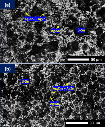
Figure 2. Microstructure of (a) SAZ and (b) SAZ-B alloys.
Download figure:
Standard image High-resolution imageEDS analysis of the as-fabricated alloys identified the IMCs phase structures, as shown in figure 3 and table 2. The IMCs phases are a mixture of Ag3Sn, ζ-AgZn, and γ-AgZn (Ag5Zn8). The IMCs formed in the studied alloys are worthy consistent with those published earlier [11, 49, 51]. XRD analysis proved the existence of these IMCs phase in the alloys. As mentioned recently, for SAZ alloy, the primary β-Sn phase changes to γ-AgZn [52]. As compared to the softer nature of the Sn matrix, the IMCs are stronger and more brittle, consequently, affect the creep properties of LFS [53, 54]. Besides, as seen in figure 2(b), SAZ-B solder exhibited microstructure refinement and homogeneous distribution of IMCs caused by applying RMF. As well, the particle's lamellar spacing was reduced [55]. Moreover, RMF decreased the gradient (imbalance) of the solution within the melt and the melt stirring accomplishes this using electromagnetic force. Also, using the magnetic field produces a more homogeneous melt, which contributes to the heterogeneous nucleation of IMCs. Moreover, a further stirring of the IMCs in the melt prevents their agglomeration and extra growth. Regular distributions of IMC precipitates and their ability to hinder crack propagation and dislocation improve the creep resistance of LFS [32]. As noticed, the RMF does not change the phase component for SAZ solders, however, it can remarkably alter the size, shape, and distribution of the phases in the alloys. Results are in good agreement with that obtained by Wu et al [55]. Similarly, Liu showed that the chemical compositions of the formed IMCs of Sn-Bi/Cu with applying magnetic field were identical to those founded without applying a magnetic field [56]. Moreover, Zeng et al showed that permanent magnet stirring produced decreasing surface pinholes, inducing melt agitation, central porosity, grains refinement, and tensile properties improvement of the Sn-20wt%Pb ingots [57]. Obviously, RMF increased the coarse eutectic regions while diminished the fine eutectic regions. Moreover, the forced melt convection in SAZ alloy with RMF eliminates the macro-caused by gravity and enriches the large dendrite's vibration resulting from the periodic convection around the dendrites. Interestingly, the IMCs break down and change into smaller ones with RMF. These results are consistent with the previous results for Sn-Bi alloy [58].

Figure 3. The identified phases structures: β-Sn matrix, Ag3Sn, and AgZn IMCs for SAZ and SAZ-B solder alloys.
Download figure:
Standard image High-resolution imageTable 2. EDS analysis of the elemental composition of IMCs phases.
| at% | ||||
|---|---|---|---|---|
| Spectrum | Sn | Ag | Zn | Phase identification |
| Spectrum 1 | 100.00 | — | — | β-Sn |
| Spectrum 2 | 86.64 ± 1.46 | 11.61 ± 1.35 | 1.75 ± 1.04 | Ag3Sn |
| Spectrum 3 | — | 32.52 ± 1.12 | 67.48 ± 1.55 | γ-AgZn + ζ-AgZn |
In brief, the advantages of the present approach technique will become beneficial for improving the microstructure and creep characteristics of LFS.
3.3. Tensile creep behaviors
As well-known, creep has been used to model many essential engineering processes that include health monitoring of bridges and buildings, metal forming, and welding [59, 60]. Also, creep is the most important controlling deformation mechanism to understand the deformation and breakdown behaviors of the microelectronic packages. As well, the creep performance of LFS is pivotal to assess the lifetime. Heterogeneous microstructural coarsening regions are preferable locations for initiation creep cracks hence, stabilization of uniform and fine microstructures is one method for enhancing solder reliability. Hence, attempts have been made to improve the creep properties of LFS. Figure 4 shows a compilation of representative creep curves of the as-cast SAZ and SAZ-B alloys at temperatures T = 25, 70, and 110 °C and stress, σ ranging from 13.6 to 17.5 MPa. Results exhibited typical creep behavior with primary, steady-state, and tertiary creep regimes for both alloys. Clearly, under constant temperature and stress, the differences in the strain rate,  propose a vital variation in the internal stress of SAZ and SAZ-B alloys. The creep strain and strain rate increased while rupture times decreased with increasing temperature and/or stress. Besides, the creep strain level for SAZ-B alloy is typically lower than that of SAZ alloy under the same test conditions. Specifically, figure 5 demonstrates the comparison between the creep behavior of SAZ and SAZ-B alloys at T = 25 °C and σ = 19.5 MPa. SAZ-B alloy with applying magnetic field displayed a higher creep resistance and greater creep rupture time than SAZ alloy without a magnetic field. Similarly, Ren et al showed that the magnetic field-aided solidification process enhances the creep lifetime of superalloys [61]. Likewise, Xuan et al revealed that under applying a magnetic field, the nickel-based single crystal superalloy exhibited a superior rupture lifetime because the magnetic field produced the elemental diffusivity enhancement during heat treatment, which resulted in a regular arrangement and uniformity size [62]. Moreover, the reduction in grain size decreases the concentrations of stress, and delays nucleation of the cavity, thus, the microstructure refinement of β-Sn and more dispersion homogeneously of IMCs were the primary reason for the improvement of creep resistance when applying RMF. It was also reported that the improvement in creep properties can be ascribed to the reduction of creep damages and the change of microcrack propagation locations through the fracture process, which relies on the IMCs refinement [63].

Figure 4. Creep strain-time curves at different stresses and constant temperatures (a) T = 25, (b) T = 70 and (c) T = 110 °C of SAZ and SAZ-B alloys.
Download figure:
Standard image High-resolution image
Figure 5. Comparison of creep strain versus time curves of SAZ and SAZ-B alloys at T = 25 °C and σ = 19.5 MPa.
Download figure:
Standard image High-resolution imageFigure 6 also shows the creep strain rate versus time at T = 25 °C and σ = 19.5 MPa for SAZ and SAZ-B alloys. It is noticed that the creep lifetimes are 178.6 and 316.7 min for SAZ and SAZ-B alloys. SAZ-B alloy depicted a greater creep lifetime of 56.4% than that of SAZ alloy. The results reveal RMF can prolong the thermal creep lifetime of SAZ alloy. Figure 7 illustrates the relationship between creep strain and creep strain rate for the examined alloys. The minimum creep strain rate of about 3.4 × 10⁻⁵ for SAZ and 9.3 × 10⁻⁶ s−1 for SAZ-B alloy at T = 25 °C and σ = 19.5 MPa described the steady-state creep strain rate. As seen, SAZ-B has the lowest creep rate whereas the SAZ alloy showed the highest creep rate. The SAZ-B alloy exhibited more creep resistance (∼366%) than that of SAZ alloy. Therefore, RMF enhanced the creep resistance caused by the IMCs refinement generated through solidification besides small β-Sn grains under the Lorentz force effect during melt growth [64]. The refined IMCs and grain size produce inhibition of the dislocation movement [65, 66].

Figure 6. Comparison of creep strain rate versus time curves of SAZ and SAZ-B alloys at T = 25 °C and σ = 19.5 MPa.
Download figure:
Standard image High-resolution image
Figure 7. Comparison of creep strain versus creep rate curves of SAZ and SAZ-B alloys at T = 25 °C and σ = 19.5 MPa.
Download figure:
Standard image High-resolution image3.4. Stress exponent, n, and activation energy, Q, parameters
The stress exponents, n, together with the activation energy, Q, values have been frequently used to identify the mechanisms controlling the deformation process and the operating lifetime of the alloy. n and Q values are calculated by the most common formula, Garofalo hyperbolic sine law, which is describing creep deformation at low and high stresses [67, 68]:

Where  is the steady-state strain rate, A and
  are constants,
  is the applied stress, R is the universal gas constant and T is the absolute temperature. The constant α can be determined from Eq.
  where
where  values are determined from the slope of relation σ versus ln
 (figure 8) and
  values calculated from the slope of relation ln (σ) versus ln
 (figure 9). The values of n and Q are shown in figures 10 and 11, respectively, and listed in table 3. It is noted that n values were 6.1–4.2 for SAZ and 7.4–5.5 for SAZ-B alloys at temperatures 25 °C–110 °C, respectively. In comparison, these values are well with studies on Sn, where n values ranged from 4.5 to 8.0 [69] and with those n values of SAC alloys [1]. In addition, a significant reduction of n values with increasing temperature is noticed. This shows that the impact of precipitation-strengthening is better at low temperatures, and the thermal instability of microstructure is at high temperatures. The decline of the stress exponent values with increasing temperature is due to the material's microstructure instability at elevated temperatures [70, 71]. The SAZ-B with RMF showed the highest n values consequently the best creep resistance, while SAZ without RMF showed the lowest n values subsequently the worst creep resistance. Results of the RMF effect are consistent with those reported recently [72]. Also, Drienovsky et al revealed that the mechanical improvement of the induction Sn-1.0Ag-0.8Cu alloy is owing to the homogeneous distribution of IMC phases [73]. According to the range of stress exponents estimated, dislocation climb is often the prevalent creep mechanism controlling deformation [74–76].

Figure 8. Plots σ versus ln
 at (a) T = 25, (b) T = 70 and (c) T = 110 °C for SAZ and SAZ-B alloys.
Download figure:
Standard image High-resolution image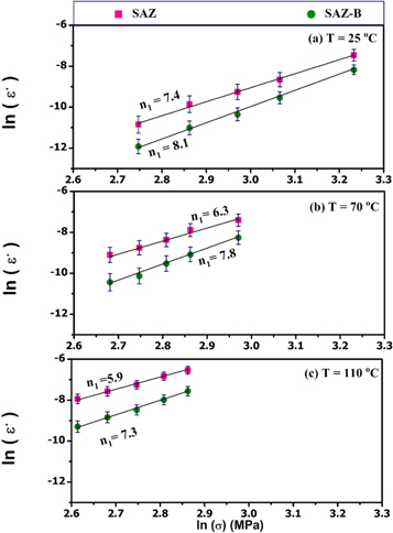
Figure 9. Plots of ln (σ) versus ln
 at (a) T = 25, (b) T = 70 and (c) T = 110 °C for SAZ and SAZ-B alloys.
Download figure:
Standard image High-resolution image
Figure 10. Stress exponent values for SAZ and SAZ-B alloys at (a) T = 25, (b) T = 70 and (c) T = 110 °C.
Download figure:
Standard image High-resolution image
Figure 11. Activation energy values for SAZ and SAZ-B alloys.
Download figure:
Standard image High-resolution image
Table 3. The stress exponent, n, and activation energy, Q, values for SAZ and SAZ–B alloys.
| Alloy | Activation Energy (kJ mol−1) | Temperature (oC) | n |
|---|---|---|---|
| SAZ | 58.3±3.0 | 25 | 6.1±1.5 |
| 70 | 5.1±1.5 | ||
| 110 | 4.2±1.5 | ||
| SAZ-B | 69.7±3.0 | 25 | 7.4±1.5 |
| 70 | 6.5±1.5 | ||
| 110 | 5.5±1.5 |
The experimental activation energies are 58.3 and 69.7 kJ/mol for SAZ and SAZ-B, respectively, as shown in figure 11 and table 3. It is remarked that the calculated Q values are lower than the Q values (100–130 kJ/mol) for tin controlled by lattice self-diffusion [77, 78]. Moreover, the values were higher than the Q values (30–40 kJ/mol) for tin controlled by grain boundary diffusion [79]. However, the Q values investigated in the present study are relatively close to that (70 kJ/mol) for the creep controlled by pipe diffusion of tin [75, 80].
4. Conclusions
The present work studied the microstructure and creep properties of SAZ alloy under applying RMF through the solidification process. The results are briefed as:
- (1)By applying RMF, SAZ-B alloy exhibited microstructure refinement and the homogeneous distribution of IMCs caused by RMF hence influences the creep properties of LFS.
- (2)SAZ-B alloy with applying magnetic field displayed a higher creep resistance and greater creep lifetime than those of SAZ alloy without the magnetic field at all tested temperatures and stresses. SAZ-B alloy depicted more creep resistance (∼366%) and creep lifetime (56.4%) than those of SAZ alloy at room temperature.
- (3)The stress exponent parameter was 6.1–4.2 for SAZ and 7.4–5.5 for SAZ-B alloys at temperatures 25 °C–110 °C, respectively.
- (4)The activation energy parameter was 58.4 and 69.3 kJ/mol for SAZ and SAZ-B alloy, respectively. Q values are relatively close to that (70 kJ/mol) for the creep controlled by pipe diffusion of tin.
The RMF as a viable approach may have excellent prospects for improving creep behaviors of LFS.
Acknowledgments
The authors extend their appreciation to the Deanship of Scientific Research at King Khalid University for funding this work through research groups program under grant number R.G.P. 2/69/42.
Data availability statement
All data that support the findings of this study are included within the article (and any supplementary files).
Conflict of Interest
The authors have declared no conflict of interest.