
Abstract
Dielectric elastomer actuators draw great interest in the emerging technology of soft actuations. The drifting of resonance frequency and variable stiffness are commonly existed in soft actuations. This work studied the dynamic performances of a cylindrical dielectric elastomer actuator with coupled loads of tensile forces and variable voltages. The equation of motion for the axial are derived from Euler–Lagrange equation and are reduced into linear ordinary differential equations by the weighted average equivalent linearization method. It is found that the resonant frequency as well as the dynamic behavior can be tuned by variable electrical stimulus on the actuator. An analytical solution of the resonant frequency and equivalent stiffness have been derived in this paper, and have been verified by numerical simulations and experimental measurements. By changing the excitation voltages, the stiffness can be tuned as variable and controllable, which paves the way for future applications of the DE actuators with better performances and resilience.
Export citation and abstract BibTeX RIS

Original content from this work may be used under the terms of the Creative Commons Attribution 4.0 licence. Any further distribution of this work must maintain attribution to the author(s) and the title of the work, journal citation and DOI.
1. Introduction
The dielectric elastomer actuator (DEA), known as 'artificial muscles', is a promising artificial muscle technology, which can deform under the stimuli of voltage [1, 2]. For the application of soft actuation, DEAs exhibit many desired properties, e.g., large deformation, high energy density, fast response, low weight, variable stiffness, and low cost [3, 4]. These properties of DEAs impart them with potential uses such as artificial muscles, tunable optics, generators for harvesting energy, tactile sensors for Braille display, and membrane resonators [5–8]. In the mechanical design of soft actuators, there are many studies recently. However, there still remains challenges to get precision actuation control for DEAs [9, 10].
DEAs have large deformation bandwidths and hopefully can be used in dynamic excitations, e.g., frequency tuning, pumps, acoustic actuators and vibrotactile displays. There have been some noticeable studies in the dynamic behaviors of DEAs. Li et al [11] presented the dynamic equations for the visco-hyperelastic DE thin film structures, and the effect of viscoelastic and strain hardening properties on resonance frequency as well as vibration amplitude of the system are analyzed. Under the assumption of uniform deformation, Zhang et al [12] peoposed an analytical model for the dynamic performance of a homogeneously deformed viscoelastic dielectric elastomer under equal-axial, uniaxial and pure shear state. Sheng et al [13] studied the influence of material damping on the resonance frequency when a small excitation was appied under the strain equilibrium state. It is shown that the resonance frequency and excitation response of the system can be changed by applying prestress, material damping and excitation voltage to the film. The research results of Wang et al [14] showed that when the film pre-stretch value and the excitation voltage were small respectively, the film actuator could gradually reach the strain equilibrium state; otherwise, the electromechanical instability may happen. Zhang et al [15] found that for cylindrical DEAs, spring stiffness and excitation voltage can both change the resonant frequency and vibration amplitude of the actuator, but the former has a more significant effect. The above research results show that the viscoelasticity of material, the mode of action of mechanical force, and the voltage will all have an impact on the dynamic output characteristics of the DEA, e.g., affecting the output stability, resonance frequency and vibration amplitude of the DEA.
Existing literature shows that the natural frequency of dielectric elastic materials can be adjusted actively through structural design and excitation voltage, different types of dielectric elastic soft actuators have potential application advantages. Dubois et al [16] succeeded in actively adjusting the resonant frequency of the actuator by changing the excitation voltage value, and modeled the resonant frequency of the first order mode of the actuator. Zhu et al [17, 18] calculated the natural frequency of the small-amplitude oscillation around the state of equilibrium, and verified that the natural frequencies can be tuned by varying the pre-stretch, pressure and voltage. Feng et al [19] studied the oscillation of a DE-based microbeam resonator and derived the resonant frequencies of the resonator using Raleigh's method for small amplitude vibration. The above modeling of the resonant frequency of the DEA shows that the resonance frequency can be adjusted by changing the external excitation. However, it is difficult to get the analytical solutions of the resonance frequencies and thus it is hard to concern resonance frequency in actuation control algorithms.
To calculate the resonance frequency of the DEA, conventional method is using the equilibrium position of tiny perturbation method, which can only get the resonance frequency and stiffness values when the strain is stable. However, in practical applications, the actuator is in dynamic vibration process, and the resonance frequency and stiffness change with the deformation of the actuator. Therefore, the variable stiffness characteristics of the actuator can be considered from the perspective of dynamics, and the dynamic model of resonance frequency and stiffness of the actuator can be obtained.
Rolled actuators have many advantages that have been recognized previously, such as large strain and force, and uniaxial deformation. Zhao et al [20] fabricated a rolled DEA and optimized the conbinations of different elastomers and CNT electrodes to achieve large strain and force. The bandwidth of the actuator is up to 200 Hz, the blocking force and free displacement are 1 N and 1 mm respectively, all within a volume of less than 1 cm3. By carefully selecting and processing ultrathin carbon nanotube electrodes, Wood et al [21] reported a soft composite DEA, which has a peak energy density of 19.8 J kg−1, higher electric fields can be applied to membrane without risking dielectric breakdown. In this paper, we modeled the resonance frequency and stiffness of the cylindrical DEA. We derive the governing equation of cylindrical DEA using the Euler–Lagrange equation. The Taylor expansion of the governing equation of motion and the equivalent linearization combined with the weighted average are used for solving equivalent stiffness and resonance frequency of the cylindrical DEA. The effectiveness and accuracy of these two methods are compared. Experiments are carried out. The experimental measurements indicate that this model quantitatively expresses the dynamical factors of cylindrical DEA, and results in the solutions of stiffness and resonance frequency for further actuation control.
2. Dynamics model of a viscoelastic cylindrical DEA
2.1. Fabrication process
The fabrication process mainly incledes two parts: (i) pre-stretching and coated electrode (figure 1(b)), (ii) multilayering (figure 1(c)) and rolling (figures 1(d), (e)). Start by cutting out a piece of tape (3 M, VHB4910). On the surface of the tape, mark the areas with length and width of  and
and  respectively. The biaxial stretching of the film is carried out by a stretching mechanism, and the length and width of the calibration region in this state are
  and
and  respectively. The pre-strains in the three main directions of the membrane are defined as
  where
where  The compliant electrode is manually coated in the marked area on the upper surface of the film, the wire is connected at the right end. Stretch the second film with the same pre-stretch value. Similar to the sandwich structure, two membrane are superimposed on top of each other. The upper surface of the second film is coated with a compliant electrode and connected with a wire. The spring is compressed axially to length
  The films are then around the pre-compressed spring. Silk thread is wound at the end cover to secure the film and spring. Cut off the excess film to get a cylindrical actuator.

Figure 1. (a) A DE of dimensions: length  width
width  and thickness
  in the reference state. (b) Under the external stimuli of forces
  and
and  the DE deforms to pre-stretch state with length
  width
width  and thickness
  the flexible electrode is coated in a rectangular frame on the upper surface of the film. (c) Stack the pre-treated films on top of each other. (d) The stacked double layer film is rolled on the pre-compressed spring. (e) Cut off the excess film to get a cylindrical actuator. (f) Under the external excitation voltage
  the cylindrical DEA deforms in the axial direction.
Download figure:
Standard image High-resolution image2.2. Dynamics model
Figure 1(a) shown that the size of DE membrane in the reference state are length  width
width  and thickness
  in the Z, X and Y directions, respectively. Figure 1(b) illustrates that the DE membrane is pre-stretched by mechanical forces
  and
and  in the
  and
and  directions, respectively. Define the pre-stretches as
  Two films of the same treatment are glued together. As shown in figure 1(d), a spring with a stiffness of K, radius r, and free length of
  is axial pre-compressed to
  A double layer of dielectric elastomer is rolled around the spring to form a cylindrical dielectric elastomer actuator.
When voltage  is applied, the actuator will deform, and the stretches of the film in the three direction of length, width and thickness change to
  and
and  respectively. In continuum mechanics, the material coordinate (X, Y, Z) and the spatial coordinate (x, y, z) label a certain material point in the reference state and the deformable material point, respectively. For incompressible dielectric elastomer membrane(
 ), the motion of the actuator can be written as:

The dynamic governing equation of cylindrical DEA is expressed by the Euler–Lagrange equation:

where  is the derivative of
  with respect to time.
  is the Lagrange, T is the kinetic energy of the system, U is the potential energy produced by the conservative forces in the system.
The kinetic energy of the system is as follows:

 is the density of the membrane,
  is the volume of the membrane,
  and
and  are the deformation velocities of the film in three directions respectively. It is assumed that the mass of the spring is negligible.
The rheological model was used to characterize the deformation process of dielectric elastomer materials [22–24]. As shown in figure 2, the model is divided into two parallel parts. The first part contains a reversible deforming spring  and the second part contains a series spring
  and damping. The free energy of cylindrical DEA consists of three parts: membrane elastic energy, electric energy and spring elastic potential energy. Based on the assumption of uniform deformation, the elastic energy of the membrane is obtained by multiplying the free ennergy density of the menbrane by the volume.

Figure 2. Standard rheological model.
Download figure:
Standard image High-resolution imageIn which  and
and  are the shear moduli of spring
  and spring
  respectively,
  and
and  are a constant associated with the tensile limit of DE material,
  and
and  are the damping strains in two directions of the film plane respectively.
  is the permittivity of the material,
  is the normal electric field. The strain of spring
  in the two directions of the film plane is
  which is obtained from the strain of spring
  in the corresponding direction and the strain of damping (
 ). Damping is regarded as Newtonian fluid in this paper, and the strain rate of damping is
  and
and  the relation between the strain rate of damping and the strain rate of spring
  is [25, 26]:


Where  is the viscosity of the dashpot.
Previous research data of our research group shows that the axial deformation of the actuator is influenced by the number of winding loops of the film N. When other conditions are determined, the largest axial deformation of the actuator is obtained when N = 6. Therefor the number of winding loops of the actuator studied in this paper is N = 6. The length of the film in the first circle satisfies:  The thickness of the film after pre-stretching is
  and the double layer film is superposition during winding. The length of the film in the second round is
  and so on, the circumferent length of the film after six rounds of winding is
  Because the film is tightly attached to the spring, within the safe deformation range of the film, the deformation of the film in the circumferential direction can be ignored, so that
  According to the incompressibility of the material,
  Therefore, according to equation (2–3), the kinetic energy of the system is simplified as:

and the potential is obtained from equation (2–4) as:
Combined with equations (2–7) and (2–8), the dynamic governing equation of the system can be obtained from the Euler–Lagrange equation:
The rate of deformation in the dashpot can be simplified by equations (2–5) and (2–6) as:


3. Nonlinear dynamic analysis
3.1. The taylor expansion of the governing equation
In order to improve the axial strain capacity of the actuator and restrain the circumferential strain, the pre-stretching of the film is satisfied  In calculation, the following material parameters are used:


 . The material parameters are substituted into the equation (2–9), and the nonlinear stiffness term in the equation (2–9) is expanded by Taylor third order at
  to obtain a new governing equation. Before voltage is applied, the cylindrical DEA has been static treated for 3–5 h, and the film strain is considered to be completely relaxed.

Where 

It is easy to understand that when the pre-stretching forces  and voltage
  are static, the axis strain of the cylindrical DEA may reach a stable state. In the equilibrium state, the governing equation equation (3–1) can be reduced to:

3.2. Linearization of the nonlinear governing equation
For equation (3–1), the coefficient of damping nonlinear term differs from other coefficients in the equation by more than 104 order of magnitude, so this term can be ignored in the governing equation:

With the initial conditions:

The linearized equation of equation (3–3) is:

The difference between equations (3–3) and (3–5) is:

According to the mean square error criterion, the unknown coefficient  is:
is:

It yields:

The periodic solution of equation (3–5) is:

Where  Based on weighted average [27]:

where s is constant.
According to the calculation criterion of equation (3–10), the average operator in equation (3–8) is:


In case s = 2, substituting equations (3–11)–(3–13) into equation (3–8), and then substituting equation (3–8) into equations (3–5) and (3–9) we get the equivalent resonance frequency and solution of the governing equation as follows:


where m = 14.08 g is the mass of the cylindrical DEA.
Equation (3–16) shows that the equivalent resonant frequency of the actuator is a function of the excitation voltage when the other parameters of the actuator are given. To further explain and explore how the viscoelasticity affects the system's dynamic response, we used Matlab to simulate the voltage curve of equivalent resonant frequency and equivalent stiffness (figure 3).
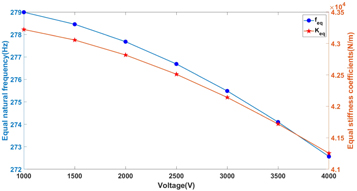
Figure 3. Equivalent resonant frequency and equivalent stiffness as a function of voltage.
Download figure:
Standard image High-resolution imageAs can be seen from figure 3, with the increase of excitation voltage, the equivalent stiffness value of the cylindrical DEA decreases. The reason for this is that electrostatic pressure causes the film to deform, making the overall actuator more 'soft' [28].
3.3. Dynamic response analysis
In the following, we study the dynamic response of the cylindrical DEA under sinusoidal voltage excitation. It can be seen from equation (3–1) that the voltage appears in the coefficient of the governing equation.The dynamic response of cylindrical DEAs is driven by dynamic system parameters of specific frequencies. Therefore, the dynamic excitation response of the actuator is a typical parametric excitation problem. Next, we study the vibration of the actuator under the condition that the harmonic voltage and the pre-stretching of the membrane are constant:

where  is DC voltage amplitude,
  is AC voltage amplitude and f is excitation voltage frequency. According to equation (3–2), when the DC voltage
  is applied to the cylindrical DEA, the axial strain of the actuator reaches a stable value,
  Similarly, when
 when
when 
 These states of equilibrium will be substituted into the following simulation process as the initial strain value. The influence of sinusoidal voltage with different excitation frequencies on the dynamic response of cylindrical DEA will be analyzed theoretically.
Measurements of the amplitude at frequencies from 1 to 500 Hz are made for three different combinations of  and
and  (figure 4). The amplitude is the half the difference between the maximum vibration strain and the minimum vibration strain under the equilibrium state. The equivalent resonant frequency is obtained by third order Taylor expansion (figure 3). When the voltage is set as
  the equivalent resonant frequency is obtained in equation (3–16) with a value of
  Similarly, when
 when
when 
 Among the three simulations, all of them exhibit one resonant frequency
  When the DC voltage is set as
  the resonant frequency is obtained in equation (2–9) with a value of
  Similarly, when
 when
when 
 The difference between the two is caused by the following two reasons: first, when the governing equation is expanded by third-order Taylor, part of the higher-order terms is discarded, resulting in some errors; second, some errors will occur in the equivalent linearization of the nonlinear governing equation. Moreover, the dynamic change process of figures 3 and 4 is same: the resonant frequency decreases with the increase of the excitation voltage.
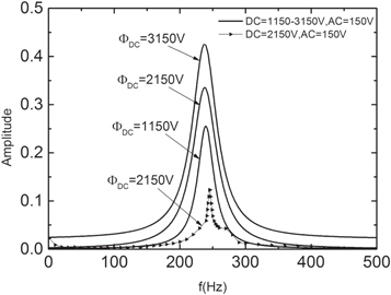
Figure 4. Frequency-domain dynamic responses of cylindrical DEA for different DC voltages.
Download figure:
Standard image High-resolution imageWhen the DC voltage amplitude is 2150 V and AC voltage amplitude is 150 V, figure 5 illustrates time-varying curve of axial strain  at super-harmonic frequency
  harmonic frequency
  and super-harmonic frequency
  Figure 5(b) indicates that when the sinusoidal voltage frequency is close to the resonant frequency
  the vibration of the cylindrical DEA is the strongest and the phenomenon of 'beating' occurs [29]. When the frequency is 1/2 the resonant frequency
  and twice the resonant frequency
  the phenomenon of 'beating' does not exist.

Figure 5. Time-varying curve of axial strain  at different excitation frequencies: (a) super-harmonic frequency
  (b) harmonic frequency
  and (c) sub-harmonic frequency
  under
under 
Download figure:
Standard image High-resolution image4. Experiment verification
Below we prepare the experiment to verify the resonance frequency value of the actuator obtained from the simulation analysis. The experimental diagram is as follows (Figure 6):
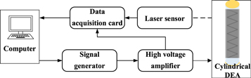
Figure 6. Schematic diagram of axial strain test for cylindrical actuator.
Download figure:
Standard image High-resolution imageThe software LabVIEW was used to generate sinusoidal signal, which was amplified by the voltage amplifier (TREK MODEL 20/20C-HS) and applied to the actuator. The free vibration displacement of the actuator was measured by the laser displacement sensor (LK-G400), and the voltage signal applied and the axial displacement of the actuator were collected by NI signal acquisition device PXIe-6361. When the sinusoidal voltage  is applied, measurements of the strain at frequencies from 1 to 500 Hz are made for the cylindrical DEA (figure 4). The actuator exhibited severe damping, because it has overdamped responses with longer response times and no overshoots as shown in figure 7.

Figure 7. Experimental response of the cylindrical DEA subject to sin voltage 
Download figure:
Standard image High-resolution image
As can be seen from figure 4, when the excitation frequency gradually approaches the theoretical resonance frequency, the strain of the actuator gradually increases and the peak appears near the theoretical value.
5. Conclusion
Using Euler–Lagrange equation, the dynamic model of axial deformation of cylindrical actuator is established. The equivalent resonant frequency and equivalent stiffness of the actuator are obtained by means of Taylor expansion and linearization of the governing equation. The equivalent resonant frequency is characterized by the materials parameters, geometric dimension. Figure 3 demonstrates the variation of the equivalent resonant frequency and equivalent stiffness with the voltage. The drift with excitation voltegies can express the nonlinear properties in dynamic responses, which cannot be concerned in any model based on Linear Time Invariant system. The reason is that higher voltage causes more soft membrane. The experimental results verified that this model is able to express the nonlinear factors of soft actuator in dynamic response process. We use the Matlab to simulate the frequency sweep of amplitude at different  values. When
  the simulation value is
  and experimental value is
  This result verifies the accuracy of the dynamic model. For the soft actuators, the nonlinear behaviours and the physics behind dominate the driving performances. So that the present method is hopefully used in future soft applications, and paves the way for future applications of the DE actuators with better performances and resilience.
Acknowledgments
This work was supported in part by the National Nature Science Foundation of China (Grant No.52075172), and Natural Science Foundation of Shanghai (19ZR1413300).
Data availability statement
All data that support the findings of this study are included within the article (and any supplementary files).