
Abstract
The remote Laser spiral welding was utilized to zero-gap lap welding of galvanized steel. The relationship between pores in the weld zone and process parameters were investigated. The combination of high keyhole velocity and small spiral spacing was found to be essential for eliminating porosity in the weld area. As the spiral pitch decreases from 0.7 mm to 0.3 mm, the porosity decreases rapidly from approximately 20% to 0%. When the spiral spacing of 0.3 mm, the porosity reaches an acceptable quality level of less than 1%. The porosity tends to decrease as the keyhole velocity increases from 3 m min−1 to 9 m min−1. At the spiral pitch of 0.3 mm and keyhole velocity of 9 m min−1, the porosity in the weld area is almost completely suppressed. The peak shear strength of the spiral weld without porosity was 8819.8 N and the peak shear strength of the spiral weld with porosity was 5104.3 N. The tensile shear performance was increased by 72.8%. The low porosity caused by the spiral laser beam improves the tensile shear strength of the oscillating weld.
Export citation and abstract BibTeX RIS

Original content from this work may be used under the terms of the Creative Commons Attribution 4.0 licence. Any further distribution of this work must maintain attribution to the author(s) and the title of the work, journal citation and DOI.
1. Introduction
In the automotive industry, galvanized steel was widely used in automotive body-in-white(BIW) manufacturing because of its superior corrosion resistance [1]. The number of spot welds in a single-vehicle ranges from 2000 to 5000, which indicated the importance of spot welding in automotive assembly [2].
Resistance spot welding of galvanized steel sheets incurs high electrode maintenance costs due to high current, long welding time, and the tendency of the zinc coating to adhere to the electrode. An experimental study showed that the electrode surface diameter expansion, whether axially or radially, was much faster for welding galvanized DP600 than for ungalvanized steel [3]. After 1200 welds on 0.8 mm thick DP600 steel, the electrode diameter expanded by 1.9 mm, while after 1500 welds on steel without zinc coating, the electrode diameter expanded by only 0.52 mm. The presence of zinc coating significantly reduces the service life of the electrode.
Therefore, there has been a great deal of research in searching better performing alternative connection methods. Remote laser welding (RLW) has become an attractive research technology in the field of welding due to its faster welding speed, lower heat input, and higher manufacturing flexibility [4]. Changing the resistance spot welding structure to the corresponding laser welding structure could significantly reduce the weight of the body-in-white structure by 12.2 kg [5]. Remote laser welding (RLW) can maximize structure integrity by performing custom-shaped welds, which can not only reflect the original intent of the assembly designer but also improve production efficiency [6]. However, due to the excessive difference between the evaporation temperature of zinc of 906 °C compared the melting temperature of steel of 1538 °C, highly pressurized zinc vapor tends to be generated at the melt interface. Therefore, successful laser welding of galvanized steel in a zero-gap lap joint structure is extremely challenging. A substantial amount of research efforts have been carried out to solve the above issues and several solutions have been proposed. To allow the high-pressure zinc vapor to escape readily, the usual solution is to create an appropriate gap between the lap surfaces of the galvanized steel sheets. To create a gap, Chen, G et al [7] suggests placing shims between the top and bottom sheets, or stamping the upper sheet to form a projection to create an interfacial gap. Gu, H et al [8] proposed using a pulsed laser to generate a hump in the base plate to create a gap. The above methods put forward ideas to solve problems related to the evaporation of the zinc coating during the welding process, but when these solutions were used in actual production, new problems arose. The existence of gaps can seriously affect the waterproofness and airtightness of the product.
Maintaining the gap between the base materials conflicted with the waterproof performance required by the product design [9]. Besides, even in a laboratory environment, it is difficult to maintain consistent tolerance levels between parts.
To achieve welded joints under zero-gap conditions, Ma, Kong et al [10] proposed a double-pass laser pre-scanning and welding process. The process uses a defocused laser beam with a wider beam diameter and reduced intensity during the preheating process. The experimental results showed that the zinc layer was melted or part of the zinc was vaporized off during the preheating process. Although the method of removing the zinc coating gives the steel sheets better weldability, at the same time, it also increases the susceptibility to corrosion.
Therefore, to solve the porosity problem in the lap joint process of galvanized steel sheets, this article adopts a new type of laser spot welding method-remote laser spiral spot welding for zero-gap lap joint of galvanized steel sheet. The spiral scanning form is conducive to the escape of gas and reduces the defects caused by the unsatisfactory escape of zinc vapor [11]. The remote laser welding has the advantage of high efficiency and energy saving, and is increasingly valued by automotive assembly lines [12]. Compared with traditional laser spot welding, the diameter of the fusion surface formed by spiral laser spot welding is larger, and the upper and lower dimensions of the nugget are more consistent. The remote laser welding applications offer significant improvements in terms of cycle time and equipment utilization. The main contribution comes from the almost instantaneous positioning of the laser beam between two geometries [13]. Yang et al [9] studied the application of remote laser welding in a zero-gap lap configuration of galvanized steel. The results show that remote laser welding can stabilize the melt pool and facilitate the escape of zinc vapor.
This paper studies the mechanism of the new laser spiral spot welding method to suppress the porosity, and analyzes the weld joint formation and mechanical properties under different spiral parameters, thereby forming a good and excellent lap joint process window.
2. Materials and methods
The welding system used for remote laser spiral spot welding was equipped with a Blackbird intelliWELD II FT galvanometer scanner, an IPG YLS-5000 fiber laser, and an ABB IRB 4600 robot in ambient air at room temperature. Figure 1(a) is a schematic diagram of a spiral scanning path used to generate spot welding. The scan path has an outer diameter of 7 mm and consists of an Archimedean spiral and a circle with a radius r of 3.5 mm. A point rotating along an Archimedean path has its angular velocity ω proportional to its line velocity v. Equivalently, in polar coordinates (r, θ), an Archimedean spiral can be described by the equation (1):

where α is selected as a parameter that turns the spiral and b controls the distance between Successive turnings. For a given b, the distanced between turning curves is constant. Because the distance D is constant, one advantage to a weld path that is an Archimedean spiral is that heat conduction through the welded material is equally spaced.
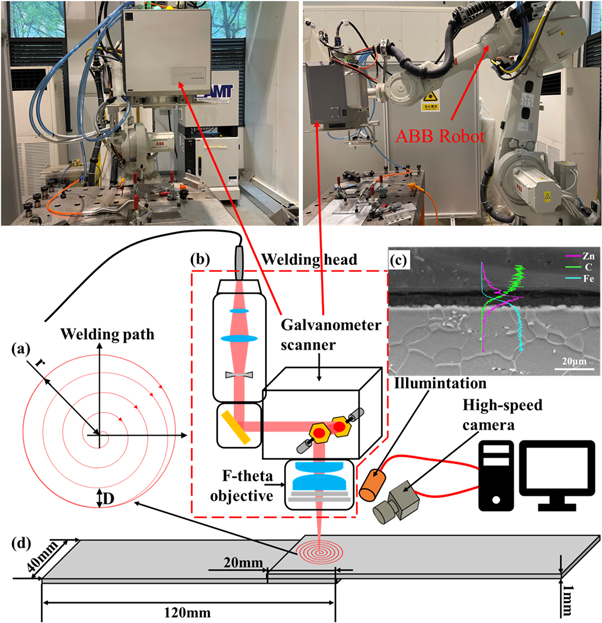
Figure 1. Schematic diagram of the remote laser spiral welding experimental set-up. (a) Laser scanning path; (b) Scanning the weld head; (c) Microstructure and EDS analysis of the zinc coatings. Purple line: Zn; green line: C; blue line: Fe; (d) The size of the specimen for tensile shear test.
Download figure:
Standard image High-resolution imageThe laser beam wavelength is 1060 nm and the fiber diameter is 200 μm. The scanner includes a collimating lens with a focal length of 450 mm and an f-θ focusing objective with a focal length of 150 mm. The focal diameter R of the laser beam is 0.6 mm, as shown in figure 1(b).
The material used in this test is a double-sided galvanized ST12 low-carbon steel sheet with a size of 120 mm × 40 mm × 1 mm. The mechanical properties and chemical composition are shown in table 1. The base material galvanized steels with a plating thickness of about 10 μm were used for all experiments, as shown in figure 1(c). The focusing plane of the laser beam was set on the upper surface of the top sheet. The appropriate welding power and scanning speed were selected to ensure sufficient nugget dimensions at both upper and lower surfaces. Process parameters are shown in table 2. For the optimization of formation and poor porosity, the parameters were optimized. To investigate the reason that the remote laser spiral welding had good porosity suppression capability, high-speed video observation of the welding process was carried out. The high-speed charge-coupled device (CCD) camera used was a Phantom VEO 640 with a resolution of 1280 × 600 and a frame rate of 5000 fps.
Table 1. Mechanical properties and chemical components of ST12 galvanized steel sheets.
| Chemical components(wt%) | ||||||||
|---|---|---|---|---|---|---|---|---|
| Material mark | Material thickness (mm) | Yield strength (MPa) | Tensile strength (MPa) | C≤ | Si≤ | Mn≤ | P≤ | S≤ |
| T12 | 1 | 130 ∼ 260 | ≥270 | 0.1 | — | 0.5 | 0.035 | 0.035 |
Table 2. Welding parameters used in this study.
| Laser beam scanning Speed, v (m min−1) | Laser power, P (W) | Spiral pitch, D (mm) |
|---|---|---|
| 3 | 2000 | 0.3 |
| 3 | 2000 | 0.5 |
| 3 | 2000 | 0.7 |
| 5 | 2500 | 0.3 |
| 5 | 2500 | 0.5 |
| 5 | 2500 | 0.7 |
| 7 | 3000 | 0.3 |
| 7 | 3000 | 0.5 |
| 7 | 3000 | 0.7 |
| 9 | 3500 | 0.3 |
| 9 | 3500 | 0.5 |
| 9 | 3500 | 0.7 |
Before welding, the surface of the steel plate was ultrasonically cleaned in acetone for 15 min to remove the contaminants adhering to the surface and then dried in a drying oven at 150 °C for 2 h. Each metallographic specimen was ground, polished, and etched with 4 ml of HNO3 and 96 ml of CH3CH2OH solution. The microstructure and fracture morphology of the joints were analyzed by optical microscopy, scanning electron microscopy (SEM), and energy spectroscopy (EDS). The uniaxial shear tensile test was performed on an AG-25TA Electromechanical universal tensile tester at a constant strain rate of 2 mm min−1 at room temperature. The tensile specimens, as shown in figure 1(d).
3. Results and discussion
3.1. Reduction and suppression of porosity in the weld area
Figure 2 shows the top view of the spiral spot weld with different process parameters. It can be observed from figure 2, as the keyhole speed v increases, the number, and diameter of pores on the weld surface show a decreasing trend. However, when the spiral pitch D = 0.7 mm, although the keyhole speed increases, the change of pore diameter and number of pores on the weld surface was not obvious, as shown in figures 2(a)–(d). Therefore, when the spiral pitch D is large, simply increasing the scanning speed is unable to obtain a weld with a porosity-free surface. With the same other welding parameters, a decrease in the spiral pitch D shows a rapid decrease in the number and diameter of pores on the weld surface, which is better than the results obtained by increasing the keyhole velocity. Figure 2(g) shows that the pore diameter of the weld surface pore reduces to 0.5 mm or less when v = 7 m min−1 and D = 0.5 mm. As shown in figure 2(k), when v = 7 m min−1 and D = 0.3 mm, the weld surface porosity is completely eliminated. Decreasing the spiral pitch D, both the number and diameter of the pores were reduced, and at the same time, the weld surface morphology was improved, the spiral line traces faded, and the weld surface was smoother as shown in figures 2(d), (h), and (l).
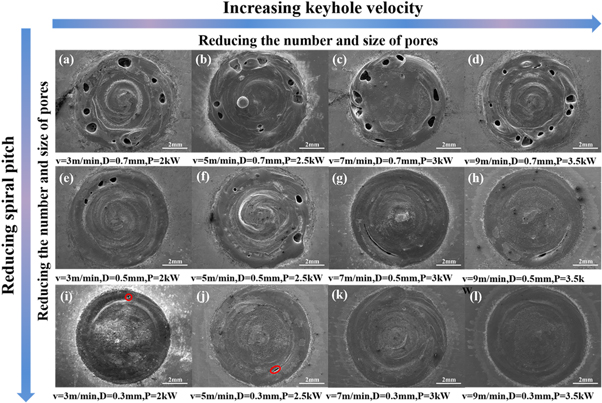
Figure 2. Top surface morphology of spiral spot welding under different process parameters.
Download figure:
Standard image High-resolution imageX-ray non-destructive tester was used to further determine the porosity of the sample welds in figure 2, and the results are shown in figure 3. In the defective samples, except for the sample with spiral pitch D = 0.7 mm where pores existed in the middle of the weld, the pores of other samples were almost all located at the edge of the weld, and most of the pores were irregular in shape and chain-like in distribution, which was typical of the pores caused by unstable keyhole. The Keyhole interrupted by flowing molten metal evolve into porosity because there was no time to overflow the molten pool.

Figure 3. The results of x-ray nondestructive testing under different process parameters.
Download figure:
Standard image High-resolution imageIn figure 3, it can be seen that the porosity of the weld shows a decreasing trend with the improvement of the welding parameters. When the spiral pitch D is set smaller and the keyhole velocity v is set larger, the porosity decreases further. Figure 3(j) shows that the pores were almost eliminated in the weld for the spiral pitch of 0.3 mm and v = 5 m min−1. With the further decrease in spiral pitch and the further increase in v, the porosity of the weld zone remains at a low level, and the grayscale of x-ray non-destructive testing is more consistent. Therefore, it means that the weld surface is smoother and the upper and lower dimensions of the nugget are more consistent.
Samples with different parameters were selected for further precise pore localization analysis. Metallographic specimens along the lap center section and transverse section were used to analyze the distribution of porosity in the depth direction and horizontal direction of the weld, as shown in figure 4. As shown in figures 4(a) and (b), the horizontal direction pores of the weld were concentrated on the outermost part of the circular weld, and the depth direction pores were distributed in the upper half of the weld. Based on the principle of pore suppression by laser-induced absorption of bubbles by keyhole, this result could be explained as follows. The outermost side is the last stage of welding, adjacent to the unmelted plate, the molten pool heat dissipation rate is very fast, liquid metal exists for a short time and solidifies quickly, so the bubbles were no time to escape from the molten pool. During the welding process, the molten metal fluid moves to the lower part of the keyhole due to gravity, forcing the bubbles to move upward, but the bubbles fail to escape due to the solidification of the liquid metal, so pores are formed in the upper sheet. Although it is difficult to suppress the porosity on the outside of the weld, it could be suppressed within a certain range by reducing the spiral pitch D and increasing the welding speed v, as shown in figures 4(c) and (d).
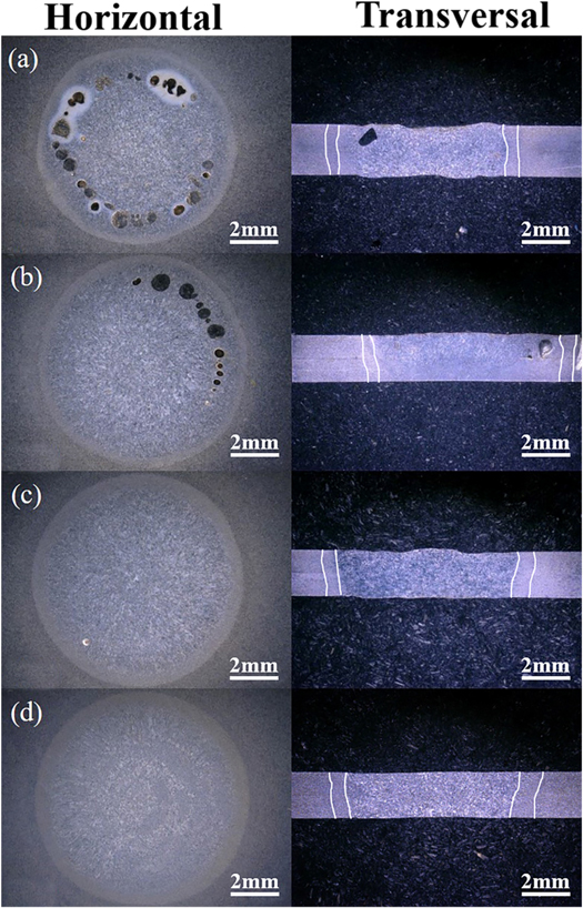
Figure 4. Metallographic specimens of horizontal section and cross section under different welding parameters; (a) P = 3.5 Kw, v = 9 m min−1, D = 0.7 mm; (b) P = 2 kW, v = 3 m min−1, D = 0.5mm; (c) P = 2.5 kW, v = 5 m min−1, D = 0.3 mm; (d) P = 3 kw, v = 7 m min−1, D = 0.3 mm.
Download figure:
Standard image High-resolution imageThe porosity, the total number of pores, and the number of pores with a diameter greater than 0.5 mm were counted for x-ray non-destructive testing with different laser parameters in figure 3. The specific method was as follows: microscopy software was used to count the number of pores and calculate the diameter and area of each pore and the area of the weld zone. Then, the sum of all porosity areas was divided by the area of the weld area to obtain the percentage of porosity of the weld. The porosity can be expressed by equation (2)

The relationship between the pores and the spiral pitch D was shown in figure 5. Figure 5(a) shows that the effect of spiral pitch D on porosity. The porosity decreases rapidly from about 20% to 0%, As the spiral pitch D decreases. When the spiral spacing D = 0.3 mm, the porosity reaches an acceptable quality level of less than 1%. Since micron-level pores are difficult to be detected by ordinary resolution x-ray non-destructive testing, the weld that detects 0% porosity may be distributed in the blue zone of the figure. Figures 5(b) and 5(c) show the effect of spiral spacing on the number of pores and pore diameter, respectively, both of which show a decreasing trend as the spiral spacing reduces. The number and diameter of the holes are significantly reduced when the spiral pitch decreases from 0.7 mm to 0.5 mm. With the further reduction of the spiral pitch to 0.3 mm, the pores were almost eliminated. The spiral pitch of 0.3 mm is a very important parameter. These results indicate that the spiral pitch plays a key role in suppressing the pores.
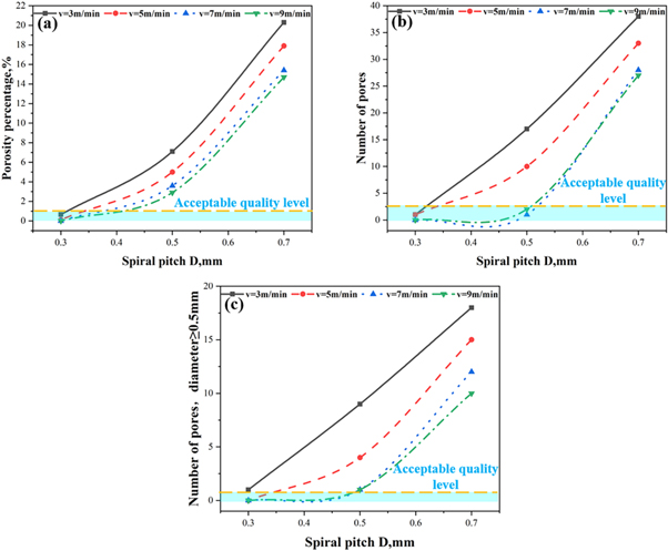
Figure 5. The relationship between spiral pitch and pore size for different keyhole velocities. (a) effect of spiral pitch on porosity; (b) effect of spiral pitch on the number of pores; (c) the effect of spiral pitch on the number of holes larger than 0.5 mm.
Download figure:
Standard image High-resolution imageFigure 6 shows the effect of keyhole velocity v on the pore. the porosity tends to decrease as the keyhole velocity increases. But just increasing the scanning speed is no way to eliminate the pores. As shown in figures 6(a)–(c), at the spiral pitch of 0.7 mm, even if the scanning speed was increased to the maximum value of 9 m min−1, the porosity remained above 14% and the number and diameter of pores were maintained at a high level. However, the pores were significantly suppressed when the spiral spacing was reduced to 0.5 mm. The results show that reducing the spiral spacing has a greater effect on pore suppression than increasing the keyhole velocity.

Figure 6. The relationship between keyhole velocity and pore size for different spiral pitches. (a) effect of keyhole velocity on porosity; (b) effect of keyhole velocity on the number of pores; (c) the effect of keyhole velocity on the number of holes larger than 0.5 mm.
Download figure:
Standard image High-resolution image3.2. Mechanism to suppress porosity
From the research above, it was found that when the spiral pitch D is smaller than the laser beam focus diameter, using the spiral pitch together with a faster welding speed can significantly suppress the formation of porosity in the weld area. The porosity was eliminated when the welding speed v is greater than 7 m min−1 and the spiral pitch D of 0.3 mm. To determine the welding mode of the spiral laser beam, the literature on deep penetration laser welding were presented below. P/d is a more appropriate threshold for evaluating keyhole mode laser welding than power density, where P is the laser power and d is the spot diameter of the laser beam on the upper surface of the plate [14]. The threshold requirement of steel is 1.33 kW mm−1. In our research, the minimum value of P/d is 2.8 kW mm−1. According to the results of the above literature, the parameters used in this paper were all-sufficient to generate keyholes in the laser welding process. Katayama, Kawahito et al [15] confirmed by x-ray transmission observation results that low welding speed is prone to the formation of porosity. It identified the faster welding speed (6 m min−1) as a key factor in eliminating porosity in laser welding. The porosity eliminating mechanism was that the faster welding speed created a specific melt flow to stabilize the keyhole. A stable keyhole means that it is difficult to create pores. The keyhole velocity of low porosity in this study is about 9 m min−1, which is higher than the result of Katayama.
To confirm the porosity reduction and elimination mechanism, the progress of the weld pool and keyhole development should be investigated. High-speed camera equipment was used to photograph the welding process. Figure 7 shows the high-speed photographic images of the welding process with different parameters. All samples scanned at a speed of 5 m min−1 showed different degrees of spattering, as shown in Figures 7(a3), (b4), and (c3). This indicates that at low welding speeds the keyhole is unstable the keyhole is interrupted by the flow of molten metal. With the keyhole closed, there is no channel for zinc vapor to escape and these vapors will cause spattering and porosity. The reason for this result can be explained as follows: the low keyhole velocity leads to the laser in a restricted area continuous heating the overlapping zinc layers, resulting in rapid evaporation of zinc in this area and the formation of highly pressurized zinc vapor, which produces explosive escape and increases the instability of the melt pool. Then, the laser beam irradiates the ruptured keyhole liquid wall that due to the recoil pressure of evaporation from the ruptured wall, causes the melt to flow downward. This phenomenon may cause large bubbles to form larger pores. When the keyhole speed is further increased to 9 m min−1, the whole spiral welding process is very stable and the keyhole is always open. After forming a stabilized keyhole from top to bottom, the zinc vapor escapes from the melt pool through the keyhole, thus no obvious sputtering is generated.
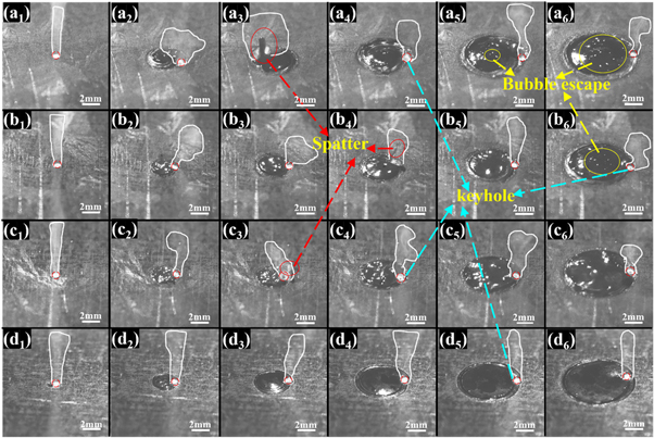
Figure 7. High-speed photographic photographs of the welding process with different parameters (a1) ∼ (a6) v = 5 m min−1, D = 0.7 mm, P = 2.5 kW; (b1) ∼ (b6) v = 5 m min−1, D = 0.5 mm, P = 2.5 kW; (c1) ∼ (c6) v = 5 m min−1, D = 0.3 mm, P = 2.5 kW; (d1) ∼ (d6) v = 9 m min−1, D = 0.3 mm, P = 3.5 kW.
Download figure:
Standard image High-resolution imageAlso, reducing the spiral pitch reduces the area of overlapping areas that are directly laser-heated by the laser beam. Therefore, the evaporated zinc vapor will have a temperature that is close to the melting temperature of steel (1809 K) rather than the boiling temperature (3133 K). The critical point temperature of zinc is about 2930 K, close to the boiling point temperature of steel, and the critical point pressure of zinc is about 2460 bar [16]. this pressure is about 49 times higher than at 1800 K. At this very high pressure, the keyhole will be extremely unstable and splash and porosity will inevitably form. This indicates that avoiding prolonged heating of the zinc coating in the overlapping areas by the laser beam and reducing the area directly heated by the laser beam are important factors in maintaining the stability of the keyhole.
The difference between the special spiral welding trajectory and traditional laser spot welding is another key factor in eliminating porosity. For conventional laser spot welding, the keyhole is always in the center, which makes it difficult for the edge zinc vapor to escape through the keyhole, resulting in spatter and holes. At the end of conventional laser spot welding, the keyhole disappears, and once the molten pool solidifies, the pores will not have a second chance to escape and become pores. However, this is not the case with spiral spot welding, where the weld pools created by adjacent spiral paths merge with each other due to heat transfer around the keyhole. Furthermore, heat conduction can increase the liquid melt pool existence time and slow down the solidification rate of the liquid metal to allow sufficient time for the generated bubbles to escape, as shown in Figures 7(a5), (a6), and (b6). The whole process is shown schematically in figure 8.
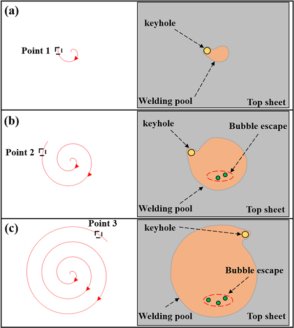
Figure 8. The spiral welding melt pool evolution and bubble escape diagram.
Download figure:
Standard image High-resolution imageDuring the spiral welding process, the pores also change considerably when the value of the spiral pitch D changes. Assuming that the laser is transferred from any position in the spiral to a position adjacent to the next spiral, the formation of the weld cross-sectional shape can be illustrated in figure 9. The keyhole of the previous spiral is A, and the keyhole of the next spiral is B. When the spiral pitch is 0.7 mm, there will be no overlap between position A and position B because the pitch is too large. When the laser beam reaches the B position, the vortex caused by the keyhole cannot affect the bubble created in the A position, and then the melt pool solidifies and forms a hole, as shown in figure 9(a). This indicates that the keyhole engulfment bubble does not work at this gap. When the spiral spacing is reduced to 0.5 mm less than the laser spot diameter, the upper part of the melt pool at position A and position B will overlap. Therefore, the bubbles generated in the upper part of position A will be caught in the vortex caused by the keyhole in position B. The vortex caused by the keyhole drives the bubble to move with itself [17]. If the bubbles do not escape from this vortex, they will inevitably encounter the keyhole and will be absorbed, and the whole process is shown in figure 10. As the spiral spacing is further reduced to 0.3 mm, it is obvious that the melt pools in positions A and B will overlap from top to bottom, and any bubbles generated in any part of position A will be captured by the vortex in position B and swallowed by the keyhole. The strong stirring effect ensures that bubbles do not escape. Therefore, the stronger stirring effect enhances the interaction between the bubbles and the keyhole, thereby enhancing the pore suppression effect. Then the stirring effect can be evaluated by the stirring Reynolds number Re expressed in equation (2):

where d is the diameter of the stirring device; μ is the density of the melt; ρ is the viscosity of the melt, and n is the stirring speed. In the spiral welding process, the keyhole caused by the laser is equivalent to the stirring device. However, as shown in figure 11, in the scanning welding process, not all the keyholes are in the molten pool. Thus, only the part of the laser beam in the melt pool can act as an agitation. The width of the keyhole part overlapping with the melt pool is called the equivalent agitation diameter dk . d and n can be converted to dk (equivalent stirring diameter) and v (keyhole velocity). Bringing the converted dk and v into equation (2), it is converted to equation (3):

where dk is related to the spiral spacing D as in equation (4):

where R is the laser beam speckle radius; D is the spiral pitch. Equation (4) is brought into equation (3) to obtain the relationship between the stirring Reynolds number Re and the spiral pitch D. as shown in equation (5):

Figure 12 shows that the calculated Re using the spiral pitch parameter. Re decreases with increasing spiral spacing, which indicates that a smaller spiral pitch can cause a greater stirring effect.
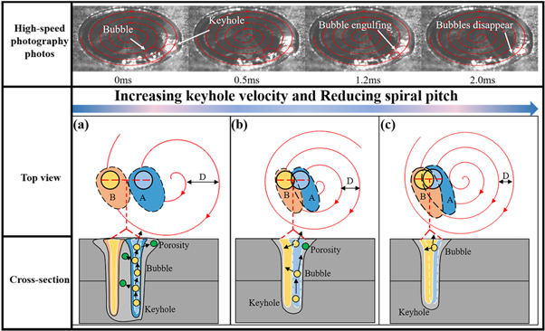
Figure 9. Schematic diagram of the formation of pore bubbles under different spiral spacing conditions and the principle of reducing the spiral spacing to suppress the pores; (a) D = 0.7 mm, v = 5 m min−1; (b) D = 0.5 mm, v = 5 m min−1; (c) D = 0.3 mm, v = 5 m min−1; the parameter of high-speed photography is D = 0.3 mm, v = 5 m min−1.
Download figure:
Standard image High-resolution image
Figure 10. Schematic diagram of the vortex caused by the melt pool and melt flow driving the bubbles to move together.
Download figure:
Standard image High-resolution image
Figure 11. Schematic diagram of the influence of the spiral pitch D on the equivalent stirring diameter dk .
Download figure:
Standard image High-resolution image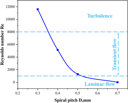
Figure 12. The keyhole speed v = 9 m min−1, the relationship between the Reynolds number and the spiral pitch.
Download figure:
Standard image High-resolution image
Figure 13. EDS analysis of the weld cross-section.
Download figure:
Standard image High-resolution imageThe chemical composition of the weld cross-section was analyzed by EDS, as shown in figure 13. From Top to Bottom, the chemical composition of the weld remains constant. The main element is Fe, and there is almost no Zn element. This shows that during the spiral welding process, the zinc element evaporates at a high temperature and is discharged through the laser keyhole without remaining in the weld. At the same time, it also shows that the optimized spiral parameters can make the zinc vapor escape quickly and effectively inhibit the generation of zinc pores.
3.3. Effect of the spiral beam on mechanical properties
Tensile shear tests were performed on samples without significant macroscopic porosity on the weld surface to assess the impact. All load-displacement curves are put together for comparison, as shown in figure 14. Obviously, the spiral pitch and the keyhole speed had a significant effect on the tensile shear performance. When the scanning speed increased from 3 m min−1 to 9 m min−1, the peak load gradually increased. In which, the peak load and the corresponding tensile displacement of the sample with v = 9 m min−1 and D = 0.3 mm are the largest. Considering the effect of porosity in figures 5 and 6, there is a correlation between the tensile shear properties of the joint and the porosity in the weld zone. Apparently, the lower the porosity, the lower the number of pores, the smaller the pore size, the better the tensile shear performance. To visualize the above correlations, a statistical analysis of all peak loads on each tensile curve was summarized using a standard bar graph, as shown in figure 15. When the spiral pitch D = 0.3 mm is constant, the distribution of the peak load value also shows two levels, which are scanning speed less than 6 m min−1 and scanning speed more than 6 m min−1. When the scanning speed is less than 6 m min−1, the peak load is less than 8000 N and the maximum is 7814.9 N. At scanning speed greater than 6 m min−1, the peak load is above 8500 N, with a maximum value of 8819.8 N. 14.5% improvement in tensile shear performance compared to joints with scanning speed less than 6 m min−1. When the keyhole speed is 3 m min−1, the spiral spacing is reduced from 0.5 mm to 0.3 mm, the peak load is increased from 5104.3 N to 7699.7 N, the tensile shear performance is improved by 50.8%, and the corresponding porosity is 7.1%, and 0.65% respectively. The results show that the pores are suppressed by simultaneously increasing the keyhole velocity and decreasing the spiral pitch, which can significantly improve the shear resistance of the joint.
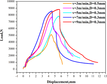
Figure 14. The relationship between load and displacement.
Download figure:
Standard image High-resolution image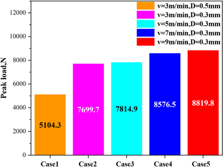
Figure 15. Peak tensile shear load of samples with different parameters.
Download figure:
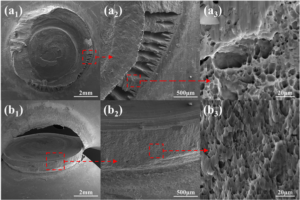
Standard image High-resolution imageFigure 16 shows the SEM images of the fracture location and the morphology of the tensile fracture surface of the tensile samples. From the figure, it can be observed that a considerable amount of pores can be observed on the fracture surface with large spiral spacing at low scanning speed, while the fracture surface with high scanning speed and small spiral spacing has no obvious pore defects. The results confirmed that the pores in the weld reduced the load area and only needed a small tensile and shear force to make it invalid. Under tensile shear, the welds with porosity failed in partial-thickness - partial-pullout (PT-PP) mode, where the cracks extend from the interface to the fusion zone, and part of the weld-thickness is removed during the separation process [18]. The dissimilarity is that welds without porosity fail in a pull-out failure (PF) mode, in which failure occurs by pulling the fusion core out of the sheet. Generally, the PF mode has a larger fracture displacement and more energy absorption, exhibiting the most satisfactory mechanical properties, making it a more desirable form of fracture in practical applications. There are more dimples on the two types of fractures. Obviously, the size of the dimple of the weld with porosity is larger than the size of the dimple without porosity, as shown in Figures 16(a3) and (b3). Only large plastic deformation and large shear stress can make small dimples. The lower porosity caused by the optimized spiral laser beam improved the tensile shear strength of the spiral weld.
Figure 16. Shear fracture characteristics for (a1) ∼ (a3) P = 2 kW, v = 3 m min−1, D = 0.5 mm and (b1) ∼ (b3) P = 3.5 kW, v = 9 m min−1, D = 0.3 mm.
Download figure:
Standard image High-resolution image
4. Conclusion
In this study, the remote laser spiral welding process was used to zero-gap lap welding of galvanized steel. A laser spot welding method was developed to eliminate welding porosity in zero-gap lap joints of galvanized steel. The main conclusions can be summarized as follows:
- (1)A mechanism for eliminating pores in zero-gap laps of galvanized steel using a spiral laser beam was investigated. The high keyhole velocity and small spiral pitch stabilize the keyhole and suppress the porosity. The corresponding porosity, number of pores, and pore size are also smaller.
- (2)In the case of other welding parameters are the same, decreasing the spiral pitch on the inhibition of pores is greater than increasing the keyhole velocity.
- (3)The spiral welding path increases the time of the liquid pool by heat conduction so that the bubbles in the pool have enough time to escape.
- (4)The reduced spiral pitch increases the equivalent stirring diameter dk leading to an enhanced keyhole stirring effect. Meanwhile, the reduced spiral pitch reduces the zinc vapor pressure, which is conducive to keyhole stability. Both together inhibit the formation of pores.
- (5)The peak shear strength of the spiral weld without porosity was 8819.8 N and the peak shear strength of the spiral weld with porosity was 5104.3 N. The tensile shear performance was improved by 72.8%. The low porosity caused by the spiral laser beam improved the tensile shear strength of the oscillating welds.
Acknowledgments
This research was supported by Foundation of Natural Science Foundation of China (52075317), the Royal Society through International Exchanges 2018 Cost Share (China) scheme (IEC\NSFC\181278), Shanghai Sailing Program (19YF1418100), Shanghai Science and Technology Committee Innovation Grant (19511106400, 19511106402), Karamay Science and Technology Major Project (2018ZD002B), Aid for Xinjiang Science and Technology Project (2019E0235), Shanghai local colleges and universities capacity building special plan project (19030501300).
Data availability statement
All data that support the findings of this study are included within the article (and any supplementary files).
Declaration
⊠ The authors declare that they have no known competing financial interests or personal relationships that could have appeared to influence the work reported in this paper.
□ The authors declare the following financial interests/personal relationships which may be considered as potential competing interests:
The authors declare that availability of data and material
The authors declare that they consent to participate.
The authors declare that they consent for publication.