
Abstract
High-performance copper-based pantograph slide materials play a crucial role in the rapid development of modern urban rail transit urgently. Herein, a full density graphite/copper-alloy matrix composite for pantograph slide has been successfully obtained by the hot powder forging process. The composite exhibits the full density when forging energy density is 307.6 J cm−3. In addition, the influence of different aging treatments on microstructure and mechanical performances of the composite has been studied in detail. The hardness and resistivity of the forged materials are greatly improved after an optimum aging treatment. Simultaneously, the friction and wear performances with or without currency current have been investigated, which demonstrates the friction coefficient can reach the minimum of 0.109 under 35 N. In current-carrying friction, the wear rate of the composite is an extremely small value of 5.5 × 10⁻⁵ mg m−1 after the aging treatment, indicating the outstanding anti-friction and self-lubricating performance. All the comprehensive analyses illustrate the full density graphite/copper-alloy matrix composite with excellent mechanical shows an enormous potential for pantograph slide.
Export citation and abstract BibTeX RIS

Original content from this work may be used under the terms of the Creative Commons Attribution 4.0 licence. Any further distribution of this work must maintain attribution to the author(s) and the title of the work, journal citation and DOI.
1. Introduction
Pantograph slide, a component of electric rail locomotives' electrical system, plays a vital role in electric locomotives' electrical power transmission and regular operation. Hitherto, many series of researches concerning pantograph slide have been emerged all over the world [1–5]. Pure carbon, metal-impregnated carbon materials, and copper-based graphite composite materials are as the primary candidates for pantograph slides. Pure carbon and metal-impregnated carbon strips, which show low impact resistance, are not suitable for electric locomotives under complex operating conditions. In contrast, copper-based graphite composite has been widely applied in urban rail transit locomotives and low-speed freight trains, owing to its superior electrical conductivity, excellent mechanical performance, self-lubrication, and anti-friction performance. However, the fabrication of full density copper-based graphite composite materials with outstanding performance invariably faces challenges.
It is well known that copper and graphite only combined by mechanical interlocking due to poor wettability of each other. The wetting angle between copper and graphite is still as high as 140°, even in a high-temperature environment of 1000 °C [6–8]. Hence, copper-based pantograph slide material manufactured by the traditional powder metallurgy (PM) method presents loose structure and relatively low densification. A host of pores remain after compression, and volume expansion is inevitable after sintering, which seriously affects materials' density and overall performance [9]. In addition, due to the large density difference between the added components and the matrix powder, component segregation is easy to occur during the mixing process [10]. Meanwhile, it's difficult for certain metal components and copper matrix to achieve complete alloying because of the low solid solution ratio, which results in reducing the materials' performance and limiting the development of copper-based pantograph slide materials. Besides, the material must overcome its deformation resistance to densify during the plastic forming process. Though several techniques have been used to produce copper-based graphite composite materials, including pre-coat on graphite [11–13], microwave sintering [14, 15], spark plasma sintering SPS [16, 17], hot pressing sintering [18, 19], these methods all could be difficult to realize high densification. Therefore, it is necessary to find a new method different from the conventional powder metallurgy process to produce fully dense pantograph slide materials, and hot powder forging is a promising choice [20, 21]. The hot powder forging adopts the powder metallurgy method to acquire initial preform, which combines the characteristics of the high utilization rate of powder metallurgy materials and compact plastic deformation of precision forging: reduction of material forming procedures and low costs; outstanding product performance and uniform phase distribution [22–26].
Herein, hot powder forging was conducted to consolidate the copper-based graphite composites for pantograph slide. Finite element simulations were employed to find suitable forging energy density. The aging treatment was used to improve the hardness of forged materials in order to meet the requirement of the practical application. The microstructure and mechanical properties of the composite could reflect the influence of the forging energy density and the aging treatments on the forged parts directly. The aim is to reference the industrial production of high-performance copper-based pantograph slide materials.
2. Experimental procedure
2.1. Preparation of materials
To obtained graphite clusters, the electrolytic copper powder (−200 mesh, ≤0.0750 mm), graphite powder (−200 mesh, ≤0.0750 mm), and E51-epoxy resin underwent mixing, drying, and sieving. Graphite clusters and several kinds of metal powder were loaded in a V-type mixer to mix for 2.5 h according to the preset ratio in the closed condition. The used powder are as follows: graphite (−200 mesh), chromium (−200 mesh), tin (−200 mesh), nickel (−200 mesh), and electrolytic copper (−200 mesh). The weight percentage of electrolytic copper is no less than 60 wt%, the rest are alloy elements. The metal powders all were purchased from General Research Institute for Nonferrous Metals, the graphite was purchased from China National Pharmaceutical Group Co., Ltd All powders are analytically purity. Subsequently, the mixture powders filled in the steel mold were uniaxially compacted by 700 MPa to obtain a preform. The green preform was sintered at argon-hydrogen mixed gas at 500 °C–900 °C to obtain sintered bodies for 3–4 h. The sintered body was preserved heat at a temperature of 600 °C–750 °C in N2 atmospheres and then forged by J58ZK-630 CNC Electric Screw Press with four kinds of forging energy density (257.9 J cm−3, 282 J cm−3, 307.6 J cm−3, 333.2 J cm−3). The samples obtained by the forging energy density above are marked as samples 1, 2, 3, and 4 from small to large. The dimension of the samples before and after the forging process are respectively 188 mm × 38 mm × 15.96 mm and 190 mm × 40 mm × 11.76 mm. The forging body samples were solid-solution treated in a GSL-1300X vacuum tube furnace at 820 °C for 1–3 h, and then water quenched, subsequently aged in a BTF-1700C-III tube furnace Processing in Ar gas protection. The temperature control accuracy is within ±3 °C. The aging process parameters are listed in table 1. The samples obtained by the forging energy density above mark as sample X (X = 1, 2, 3, 4). The samples treated by solution treatment mark as sample X-S (X = 1, 2, 3, 4). The samples treated by aging treatment mark as sample X-AT(X = 1, 2, 3, 4).
Table 1. Process parameters of aging treatment.
| Temperature/°C | Time/h |
|---|---|
| 450 | 1, 2, 3, 4 |
| 500 | 1, 2, 3, 4 |
| 550 | 1, 2, 3, 4 |
| 600 | 1, 2, 3, 4 |
2.2. Performance testing
The performance of pantograph slide material mainly refers to the mechanical and physical performance, which include the density, hardness, resistivity, impact toughness and tensile strength. The standard experimental samples were obtained by machining. MH-3005A was employed to measure the density of samples. MR5000 metallurgical microscope was used to observe the microstructure of the copper-based pantograph slider material. The hardness of the material was determined by HBV-30A Brinell/Vickers hardness apparatus. Each sample was tested at 5 points, and the final result value was taken from the mean measurement. Agilent 34401A digital multimeter was adopted to measure the resistivity of the material at room temperature (20 ± 1) °C by four-terminal method, and the distance between the current end and the potential end was ≥100 mm. NI150 metal pendulum impact tester was used to test impact toughness in accordance with national standard GB/T9096. Tensile tests of the matrix materials were measured on a velocity of 1 mm min−1 with an AGS-J tensile machine at room temperature. The density test is according to ASTM B962–2015 Standard Test Methods for Density of Compacted or Sintered Powder Metallurgy (PM) Products Using Archimedes' Principle. The tensile test is according to ISO 6892–1:2019 Metallic materials—Tensile testing—Part 1: Method of test at room temperature. The real image of the tensile test specimen with the dimensions shows in figure 1 and table 2.

Figure 1. Real image of the tensile test specimen.
Download figure:
Standard image High-resolution imageTable 2. Tensile standard specimen size.
| Symbol | b | c | Lc | Ld | Le | W | R1 | R2 |
|---|---|---|---|---|---|---|---|---|
| Size (mm) | 5.7 ± 0.02 | b + 0.25 | 32 | 81.0 ± 0.5 | 89.7 ± 0.5 | 8.7 ± 0.2 | 4.35 | 25 |
2.3. Characterization
X-ray diffraction (XRD) pattern of samples was carried out on an X-ray diffractometer utilizing radiation of Cu Kα, a tube voltage of 40 kV, and a tube current of 40 mA. Polish the optical metallographic (OM) samples and etch them with H2SO4:H2O2 (1:9) solution for 5–9 s. In order to observe the microstructure and the surface morphology of graphite/copper composite and study the wear mechanism of graphite/copper composite, Scanning Electron Microscopy (SEM) was used for understanding the microstructure of the samples after physical properties tests. The JSM-6490LV scanning electron microscope was employed to view and analyze the microstructure, impact fracture morphology, and backscatter morphology of the copper-based pantograph slide materials.
2.4. Experiments of friction and wear
MMW-1A wear tester was employed to carry out measurement of dry friction tests with a pin-on-disk method (MMW-1A wear tester was made from Jinan Yihua Tribology Testing Technology Co, Ltd). Various normal loads were set as 15 N,25 N,35 N,45 N, respectively. The timespan for each test was 2 h, and the friction coefficient was gathered by instrument per second. The wear rate of the sample was measured according to the mass difference before and after the test divided by the sliding friction distance. Electrical friction experiments were measured by a self-assembled experimental instrument, shown in figure 2, with a block-on-ring method under different current, including 10 A, 20 A, and 30 A. The calculation of the electrical friction coefficient is given by [3]:

Here, μ is the friction coefficient, P1 means load power while samples contact with the ring(W), and P0 means power under no contact among samples and ring(W), n is the count of sample blocks, F is the normal pressure applied to the sample block(N), and v means the relative linear velocity of the copper ring (m s−1). The wear test respectively bases on ASTM G77–17 Standard Test Method for Ranking Resistance of Materials to Sliding Wear Using Block-on-Ring Wear Test and ASTMG99–2017 Standard Test Method for Wear Testing with a Pin-on-Disk Apparatus. The disk radius is 31.7 mm, rotational speed of pin is 600 r min−1, and linear velocity is 0.56 m s−1. The ring radius is 125 mm, rotational speed of ring is 180 r min−1, and linear velocity is 1.178 m s−1.
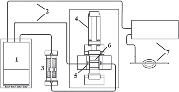
Figure 2. Schematic diagram of the apparatus for electrical friction.1-safe controllable DC power supply; 2-Wire; 3-Sliding rheostat; 4-Servo motor; 5-Sample block; 6-Copper ring; 7-Computer.
Download figure:
Standard image High-resolution image3. Results and discussion
3.1. Mechanical properties
Optical microscope (OM) images of copper-based pantograph slide composites before and after solution treatment are presented in figure 3. There is no segregation in the forged material. After forging and heat treatment, the composite material is dominated by the supersaturated α phase of the Cu-Sn alloy. The occurrence of crystal twins in certain grains was caused by the quenching treatment after solution treatment [2]. A few black-gray strips and irregular shapes around the copper crystal grains are graphite as a lubrication role, which cannot form a solid solution with the copper matrix. Graphite existing between the grain boundaries could prevent the grains from growing furtherly. No dramatic pore presents in the material. The elemental mapping image of copper-based pantograph slide materials is shown in figure 4. The elements of Cr, Sn, and Ni evenly distribute in the copper matrix, which means a network of microstructure forms after the aging process. Graphite appears as clusters. Evenly distributed Sn, Ni, Cr could promote the strength of copper matrix and obtain well-behaved mechanical performance of composite [27].
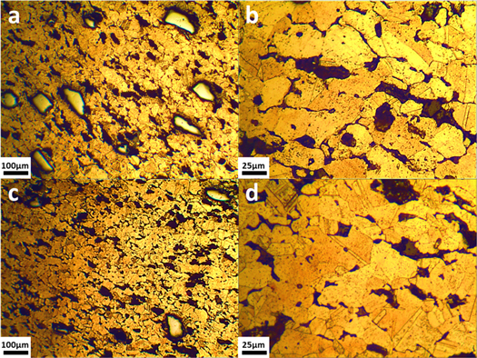
Figure 3. Morphologies of copper-based material composites forged at 750 °C without and with post solution treatment: (a), (b) as forged, (c), (d) after solution treatment.
Download figure:
Standard image High-resolution image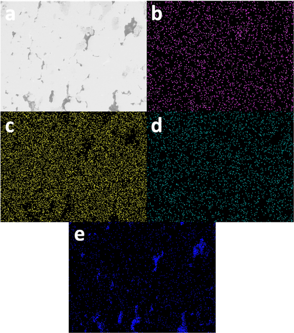
Figure 4. BSE graph elemental mapping image of hot forging copper-based pantograph slide materials. (a) BSE graph; (b) Cr element distribution;(c) Sn element distribution; (d) Ni element distribution;(e) C element distribution.
Download figure:
Standard image High-resolution imageFigure 5(a) shows the XRD patterns of copper matrix materials after solution treatment with different forging energy densities. No carbide peaks demonstrate no chemical response between graphite and other combination components, which suggests graphite is an independent phase within the composite [8]. The copper diffraction peaks shift to the direction of the angle reduction due to the variation of the copper element's lattice constant and the occurrence of lattice distortion by solid solution [28].

Figure 5. XRD patterns of copper-based materials, and Effects of aging time and temperature on hardness and electrical resistivity of copper-based pantograph slide materials (a) XRD patterns of copper-based materials (b) hardness of four kinds of samples under different forging energy density and aging temperature with 2 h (c) the diversification of electrical resistivity under different aging time and temperature for sample 3-AT (d) hardness-time curve of sample 3-AT at different temperature.
Download figure:
Standard image High-resolution imageFigure 5(b) presents the variation of hardness under different aging temperatures with 2 h for four kinds of samples. The hardness increases firstly, then falls with the ascend of temperature. The hardness of sample 3 is higher than others, which demonstrates the finite simulation result is useful for reference of the experiment. Figure 5(c) shows the variation of resistivity under different aging times and temperatures for sample 3. At the beginning of the aging process, the resistivity of the copper-based composite dramatically decreases and then slowly increases. In the initial stage of aging treatment, a number of the solute atoms transformed to the exsolution phase from the supersaturated solid solution, and the crystal lattice of the copper matrix recovered quickly. The electron scattering effect of the exsolution phase and the dislocation is much smaller than that of a solid solution, and consequently, rapid descent of the resistivity occurred. Then the resistivity decline slowly or even slightly increases due to the content reduction of solute atoms, with the exsolution dynamic gradually weaken along with the further extension of time [29]. The growth of the exsolution phase promotes lattice distortion, strengthening the effect of electron scattering, with a certain negative impact on the resistivity, resulting in a slight increase in the resistivity. From the results shown in the figure, it can be seen that the copper matrix aged at 500 °C for 3 h could obtain the lowest resistivity, which is 0.156 μΩ·m.
Figure 5(d) exhibits the variation of hardness under different aging times and temperatures for sample 3. As can be observed, the hardness of copper-based pantograph slide materials rises to the maximum value firstly and then falls. The second phase particles continuously precipitated from the copper matrix, and the precipitated phases with dispersed distribution maintained a good coherent state with the copper matrix, all of which contribute to the increment of the hardness. As the count of solute atoms remaining in the solid solution shrink, the precipitation driving force of the second phase particles became weak, the increase in the hardness of the copper alloy would correspondingly slow down. With continuous precipitation, these part particles would gradually become larger and thicker to form a stable phase, and the dispersion of particles decreases. Some precipitated phases will gradually lose the situation of coherent or semi-coherent maintenance with the matrix, and the dislocations had to pass through bypassing the coarse and non-coherent precipitate phase particles, which lead to the decline of hardness with time after reaching the peak. When the temperature of the aging treatment is too high, the decomposition of the supersaturated solid solution would be further accelerated, the crystal grains will grow and become coarser, and the increased rate of hardness became smaller. From the results shown in the figure, it can be known that the copper-based slide material aged at 500 °C for 3 h could obtain the highest hardness, 93 HB.
Figure 6 exhibits the SEM morphology of the impact fracture of the copper-based pantograph slide materials as forged and after aging at 500 °C for 3 h. As can be observed, an expansive number of dimples, which are evenly dispersed in the matrix, appear in the fracture of the material before and after the solution aging treatment. Dimples are a typical feature of ductile fracture, which indicates that the dominant mode of material fracture is ductile fracture and high plasticity of materials. Figure 6(e) suggests that the graphite cluster appears fission and extracts from the matrix. The impact toughness of composite after aging treatment is more elevated than as forged, attributed to deeper dimples than composite without heat treatment, which could absorb more energy during fracture. In addition, during the aging process, the second phase particles gradually precipitated at the grain boundaries and spread to the inside of the crystal grains, resulting in a strong pinning effect, which greatly enhanced the interfacial bonding between the grains [30].

Figure 6. Micrograph of fracture surfaces of hot forging copper-based materials without and with subsequent heat treatments (a), (c), (e) as forged and (b), (d), (f) after aging treatment at 500 °C for 3 h.
Download figure:
Standard image High-resolution imageTable 3 presents some kinds of mechanical properties of samples under different forging energy density before and after heat treatment. The density of composite increases from 8.133 g cm−3 to 8.269 g cm−3, then falls to 8.235 g cm−3 with forging energy density from 257.9 J cm−3, 282 J cm−3, 307.6 J cm−3, 333.2 J cm−3. Meanwhile, the tensile strength ascends from 179.26 MPa to 210.15 MPa then falls to 199.72 MPa after the aging process, which all higher than that of materials before heat treatment. The impact toughness shows the same tendency before and after heat treatment could achieve 8.1 J cm−2 and 10.2 J cm−2, respectively. The density of material influences the mechanical performance of materials in harmony with the simulation results. Full density material that is a material completely free of porosity, is a conceptual term. In practice, complete densification is difficult to achieve and some microporosity will generally be present. The relative density of forged material with 307.6 J cm−3 of forging energy density is 99.3% nearly fully dense with no apparent porosity in the microstructure
Table 3. Mechanical and physical properties of hot powder forging copper-based composites after forging and after aging treatment at 500 °C for 3 h.
| Tensile strength (MPa) | Impact toughness (J cm−2) | |||||
|---|---|---|---|---|---|---|
| Samples | Forging energy density(J cm−3) | Density(g cm−3) | As forged | After heat treatment | As forged | After heat treatment |
| 1 | 257.9 | 8.133 | 164.55 | 179.26 | 6.05 | 7.9 |
| 2 | 282 | 8.149 | 171.21 | 193.43 | 6.9 | 8.8 |
| 3 | 307.6 | 8.269 | 192.06 | 210.15 | 8.1 | 10.2 |
| 4 | 333.2 | 8.235 | 185.18 | 199.72 | 7.1 | 9.3 |
3.2. Wear performance
Figures 7(a), (c) is the abrasion of samples under various applied loads before and after heat treatment, respectively. With the ascend of normal load, the abrasion of samples before and after heat treatment both presents escalating trend. Sample 3 shows the lowest wear rate and friction coefficient. The abrasion of copper-based materials after heat treatment is lower than that of materials before heat treatment. Figures 7(b), (d) is the average friction coefficient of four samples before and after aging treatment under 35 N. The friction heat delivered by the load triggers an increment in nearby surface temperature, [31–33] which is beneficial for forming an oxidation layer, of which interfacial bonding with sub-surface is delicate to the variation of temperature. The interfacial bonding between the oxidation layer and sub-surface weakens rapidly, and the film will peel from the tribo-surface when the variation of temperature is too considerable. The friction coefficient of materials after heat treatment exhibits lower than that of materials before heat treatment, due to the second phase particles precipitated from the matrix during aging process strength the interfacial bonding and help material form stable lubricant film in tribo-surface. The abrasion of the composite after the aging treatment is lower than that of the composite before heat treatment because of the formation of relatively strong interfacial bonding between the oxidation layer and sub-surface after heat treatment. Before heat treatment, the matrix interface bonding force is relatively small, and the hardness of the slide material relatively low. In friction, the hard particles such as wear-resistant particles of the reinforced phase added in the material are easy to fall off from the matrix, forming abrasive grains. The existence of abrasive grains increases the abrasive wear.

Figure 7. (a) Wear rate of four forged samples under different normal load , (b) the average friction coefficient of four forged samples under 35 N, (c) the wear rate of four samples under different normal load after aging treatment under 500 °C for 3 h, (d) the average friction coefficient of four samples after aging treatment under 35 N.
Download figure:
Standard image High-resolution imageFigure 8 displays the image of tribo-surface of material in dry friction. Obvious grooves and flakey wear fragments could be seen along with the direction of friction. Plastic deformation, peeling, and adhesion pits before heat treatment could be seen. After aging treatment, there are a few microcracks and shallow furrows left by plastic deformation. The sample's friction performance before heat treatment is worse than that of the sample after treatment. It is prone to plastic deformation, confirmed by many wear debris attached to the wear surface and the irregularly shaped flaky layer. The lubricating layer will fall off from the substrate due to the weakened binding force with the subsurface and is not enough to maintain it on the contact surface and then turn into wear debris. The larger size of the lubricating layer will fall off, exposing the substrate to harsh friction [34–37]. In the friction environment, the small size of the wear debris that does not leave in time will become the abrasive particles and leave grooves on the tribo-surface, which aggravates the roughness of the tribo-surface, accelerating the wear rate of the material.
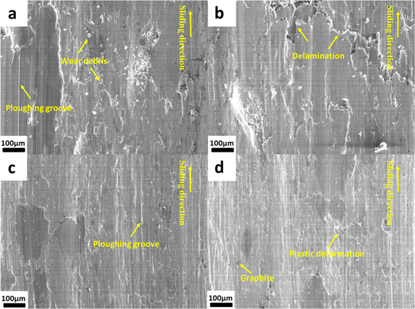
Figure 8. SEM micrographs of the worn surface of (a) sample 3 at 35 N, (b) sample 3 at 45 N, (c) sample 3-AT at 35 N, (d) sample 3-AT at 45 N.
Download figure:
Standard image High-resolution imageFigures 9(a), (c) exhibits the wear rate of copper-based materials before and after heat treatment. With the ascend of electric current, the wear rate of materials increases firstly then decreases slightly, and the abrasion of samples after aging treatment is far smaller than that of samples before heat treatment. In current-carrying friction, there is not only frictional heat but also joule heat prompted by material inherent resistance and arc heat by discharge [38]. The ascend of current accelerated the temperature rise, which promoted material softening. Material softening is a double-edged sword; on the one hand, it helps material form lubricant film on the contact surface [10, 39]. On the other hand, it reduces interfacial bonding between the contact surface and subsurface of the matrix. The heat treatment is beneficial for improving materials' mechanical performance, greatly inhibiting the abrasion of friction material in the contact sliding process. Figures 9 (b), (d) shows the friction coefficient of sample 3 before and after heat treatment with three kinds of current values. The friction coefficient of the sample falls with the ascend of current. The vertical trend of the friction coefficient demonstrates the well-lubrication layer forming with the material softening. Although the surface of the friction pair material looks flat on the naked eye, the friction surface is bumpy in the microscopic observation. The actual contact surface is more less than the nominal contact area, contact surface friction between such objects are turned into friction of protuberance like point to point, increase the contact area of the adhesive wear and the friction coefficient. With the increase of the actual contact area of friction, the lubricating components such as graphite constantly supplement the pit of contact material surface, thereby reducing the friction coefficient of the friction material. With the increase of temperature, the lubricating film is continuously produced to repair the destructed part of worn surface, prompting the lubricating film denser than beginning, and reduces the friction coefficient. However, when the temperature is high, the film destructed rate is bigger than the formed rate, and the film falls off faster, which shows that the abrasion increases and the friction coefficient increases. The friction will make lubricating film experience a virtuous cycle as destruction-formation-re-destruction-re-formation, which promotes the friction coefficient presents a gentle trend in the later stage of friction.

Figure 9. (a)The variation of wear rate of forged materials (b) the friction coefficient of sample 3-AT under 10 A,20 A,30 A (c) the variation of wear rate of copper-based materials after aging treatment under 500 °C for 3 h (d) the friction coefficient of sample 3-AT under 10 A,20 A,30 A.
Download figure:
Standard image High-resolution imageFigures 10(a), (c), (e) are the worn surface of material before heat treatment, while figures 10(b), (d), (f) show the worn surface of material after heat treatment in electric friction. Figure 11 is BSE graph elemental mapping image of copper-based pantograph slide materials after wear test. As could be observed, graphite evenly distributed to play a lubrication role. The worn surface of copper-based materials tended to be flat and smooth after aging treatment. The formation and destruction of lubricant film always occur in all stages of friction, which has a great impact on the wear and friction of materials [40]. The higher the speed of the damaging lubricant film than forming lubricant film, the higher is the abrasion of materials. What's more, the formation and destruction of lubricant film both accelerate the abrasion of friction materials. Reducing the speed of damaging lubricant film and forming lubricant film is significant for delay of friction material application life, which means developing a long-time continuous lubricant layer and an entire coverage on the contact surface [41]. Electrical-arc-induced wear refers to the phenomenon of high temperature and discharge of electric arc caused by current, undermining the contact material surface. Electrical-arc-induced wear mainly includes local melting and arc erosion caused by resistive heat, among which arc erosion is the main factor causing serious wear of materials. The abrasion of copper-based materials after aging treatment is lower than that of forged materials, indicating aging treatment is helpful for inhibiting electrical-arc-induced wear.
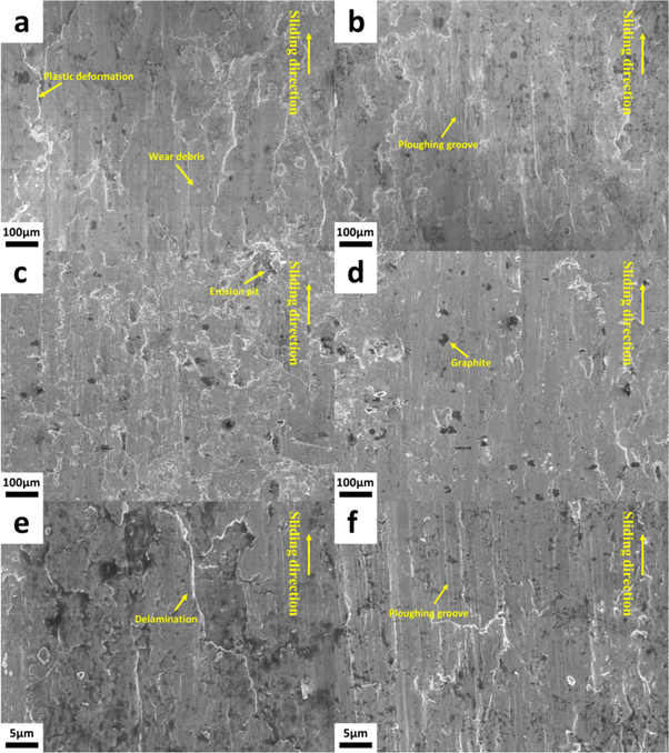
Figure 10. (a) Worn surface of sample 3 under 20 A, (b) Worn surface of sample 3-AT under 20 A, (c) Worn surface of sample 3 under 20 A, (d) Worn surface of sample 3-AT under 20 A, (e) 2000× magnified image of worn surface of sample 3 under 30 A, (f) wear surface of sample 3-AT under 30 A after aging treatment.
Download figure:
Standard image High-resolution image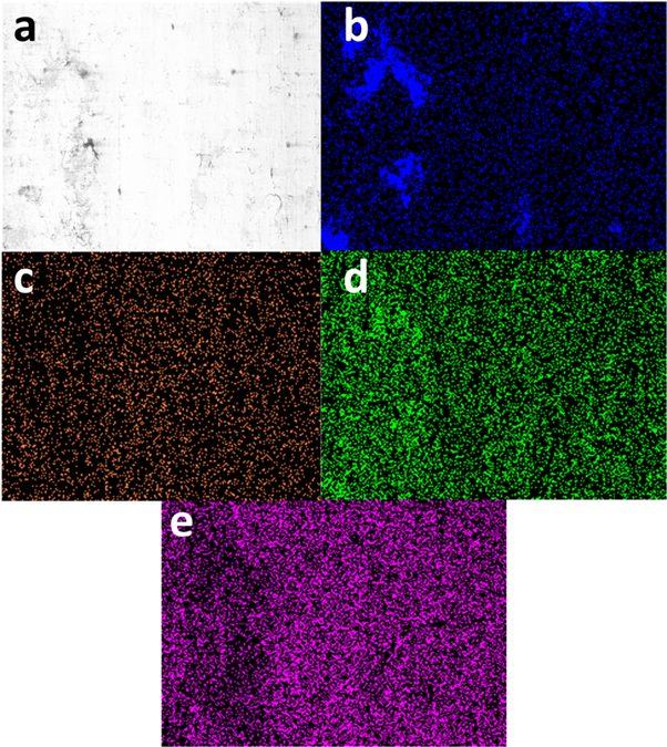
Figure 11. BSE graph elemental mapping image of copper-based pantograph slide materials after wear test. (a) BSE graph; (b) C element distribution;(c) Cr element distribution; (d) Ni element distribution;(e) Sn element distribution.
Download figure:
Standard image High-resolution image
4. Conclusions
In conclusion, full density graphite/copper-alloy matrix composites for pantograph slide were successfully manufactured by hot powder forging. The composite exhibits the full density when forging energy density is 307.6 J cm−3. The elements of Cr, Sn, and Ni evenly distributed in the copper matrix. The hardness and resistivity of materials could reach the maximum of 93 HB and the minimum of 0.156 μΩ·m under aging temperature 500 °C for 3 h, respectively. After aging treatment, the matrix interface bonding force increase, and the hardness of the slide material ascend. The copper-based graphite pantograph slide materials in this article possess low resistivity, suitable hardness, and high impact toughness, all of which meet the requirement of practical application.
Though obvious fluctuation appears in dry friction condition, the friction coefficient could reach the minimum of 0.109. In current-carrying friction, dominant mechanisms are abrasive wear and electric-arc-induced wear, and the wear rate of material could reach nearly zero after the aging process, which means longer service time. All results manifest that hot powder forging could be explored as a promising method for manufacturing copper-based graphite composite for pantograph slide.
Acknowledgments
This work was supported by grants from the National Natural Science Foundation of China (Grant No. U1632151), the Key Research and Development Project of Anhui Province of China (Grant No. 1704a0902023).
Data availability statement
All data that support the findings of this study are included within the article (and any supplementary files).