
Abstract
Inspired by the effect of angle between feather shaft and the feather vane on strength enhancement of feather structure, carbon fiber reinforced epoxy resin composites with eagle feather structure were prepared successfully. Based on liquid-phase oxidation, wettability of carbon fiber was improved, which enhanced bonding strength between reinforcement and matrix and built material base for mechanical strength of bionic composite. With the increase of carbon fiber content (0.1 wt.%, 0.2 wt.%, 0.3 wt.% and 0.4 wt.%), tensile strength and impact toughness of carbon fiber reinforced epoxy resin composites increased first and then decreased. Composites with 0.2 wt.% carbon fiber exhibited optimal mechanical properties, which was used for preparation of bionic composite. Compared with carbon fiber reinforced epoxy resin composite with the traditional vertically arranged structure, the composite material with the bionic structure owned higher tensile strength and impact toughness. The fracture and drawing out of carbon fiber and crack deflection were mechanical mechanism of bionic composite, which provided a new design and preparation method for carbon fiber reinforced epoxy resin composite.
Export citation and abstract BibTeX RIS

Original content from this work may be used under the terms of the Creative Commons Attribution 4.0 licence. Any further distribution of this work must maintain attribution to the author(s) and the title of the work, journal citation and DOI.
1. Introduction
Fiber reinforced resin composite is based on dispersing the fibers in a matrix which acts as a binder and transfers forces to the fibers across the fiber-matrix interface [1–3]. This exhibits excellent mechanical properties of composites. Due to the advantages of easy fabrication, economy and high mechanical strength, fiber reinforced resin composites are wildly used in aerospace, automotive, building and sport equipment [4, 5].
Carbon fiber, glass fiber and basalt fiber are the typical fiber materials. Compared with glass fiber and basalt fiber, carbon fiber own characteristics of high strength, elastic modulus and light weight, extending application fields of carbon fiber reinforced materials in high technology products [6–8]. Epoxy resin has been widely used in industrial fields on base of high mechanical behavior, chemical resistance, availability and light weight [9–11]. Compared with the common materials including aluminum alloys and steel, the addition of carbon fiber into epoxy resin was a useful method to improve tensile elastic modulus of composite, which built functional base for applications. [12–15]
In the practical application, the carbon fiber with relative low wettability restricted the mechanical behavior of the composites [16]. Therefore, how to improve the bonding strength between carbon fiber and matrix is the key point for mechanical strength of carbon fiber reinforced epoxy resin composites. The heat treatment [17], liquid-phase oxidation or electrochemical oxidation [18–20], plasma treatment [21–23], gas-phase oxidation [24] and high-energy radiation technique [25] are typical effective methods to improve wettability of carbon fiber. The surface energy of carbon fibers and the interface shear strength between carbon fibers and epoxy resin were increase from 76.06 MPa to 96.73 MPa via treatment of K2S2O8/AgNO3 [26]. Combined H2SO4/HNO3 treatment, sonication and temperature conditions, Zhang [27] and co-workers realized the excellent wettability of carbon fibers. Compared with other treatments, liquid-phase oxidation owns the advantages of simple operation, low cost and high efficiency. Liquid-phase oxidation have been adopted widely to enhance the mechanical strength of carbon fiber reinforced epoxy resin composites effectively. Even though many kinds of research methods have been adopted to improve mechanical properties of carbon fiber reinforced epoxy resin composites, the mechanical properties including tensile strength and impact toughness need be improved further to satisfy rigorous application demands [28, 29]. After tens of millions of years of evolution, birds evolved structures that can cope with flight, which is a highly complex movement method. Feather has been considered as a structure to provide flight power and load-bearing, exhibiting good mechanical properties [30–32]. Vasileios [33] and co-workers created a feather structure of CNT (carbon nanotube) reinforced electrospinning nanofiber interlayer system. The carbon fiber reinforced epoxy resin composite with feather structure owned high mechanical properties and light weight characteristic. The characteristics of feather structure provide a new bionic design model for improving mechanical properties of carbon fiber reinforced epoxy resin composite.
In this paper, eagle feather was treated as the bionic model to prepare bionic carbon fiber reinforced epoxy resin composite with high mechanical properties. The short carbon fiber and epoxy resin were treated as reinforcement and matrix, respectively. After liquid-phase oxidation, the optimal carbon fiber content was selected to prepare bionic composites and disclose the corresponding enhancement mechanisms of bionic structure.
2. Experimental procedure
2.1. Material
The short carbon fibers (CF) (95% purity, ∼7 μm, Shanghai Kajet chemical Co., Ltd Shanghai, China), epoxy resin (EP) (E-44, Nantong Xingchen Synthetic Material Co., Ltd Nantong, China), polyamide resin (650 curing agent, Dingyuan Danbao Resin Co., Ltd Dingyuan, China), pure water, eagle feather, H2SO4 and HNO3 (Sinopharm Chemical Reagent Co., Ltd Shanghai, China) were used as received.
2.2. Preparation of bionic composites
2 g short carbon fibers were mixed in the 3:1 (v/v) mixture of H2SO4/HNO3 under condition of ultrasonic treatment (KQ-300E, Kunshan Ultrasound Instrument Co., Ltd Kunshan, China) for 4 h to finish corrosion process. After corrosion, the mixture was placed in a high speed centrifuge with 6000 rpm (HC-3514, Anhui USTC Zonkia Scientific Instruments Co., Ltd Anhui, China) for 5 min. Then the carbon fibers were rinsed and filtrated to pH = 7. The corroded carbon fibers were put into the electric thermostatic drying oven (101A-1E, Shanghai Experimental Instrument Co., Ltd Shanghai, China) at 60 °C to remove water.
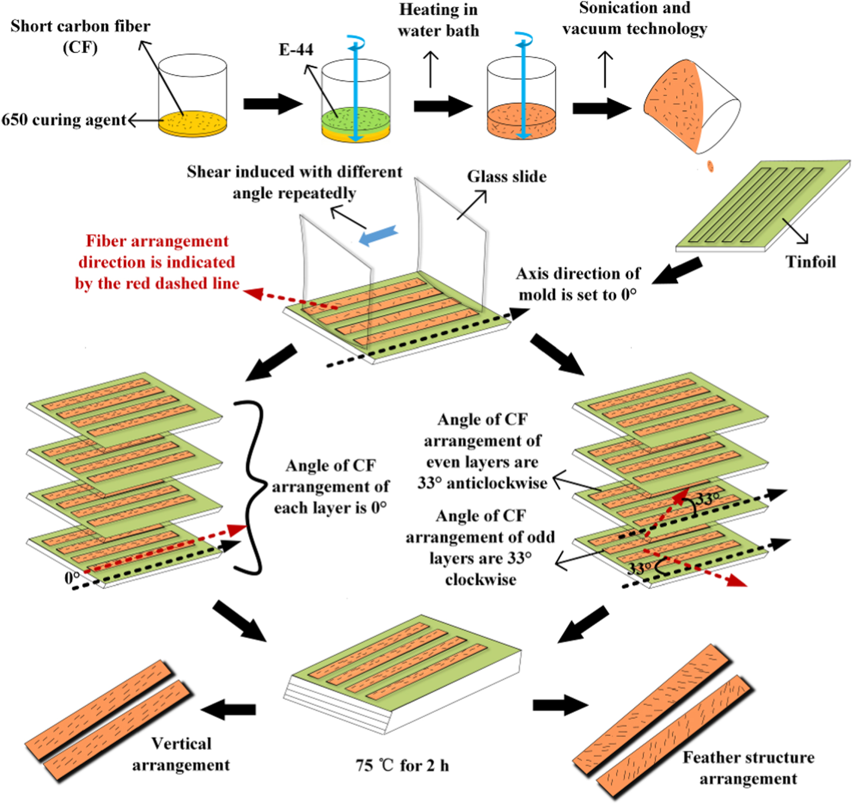
Figure 1 shows the preparation process of bionic carbon fibers reinforced epoxy resin composite. To satisfy demands of high mechanical strength and preparation efficiency, the epoxy resin and curing agent were mixed in a mass ratio of 5:3. After stirring at 60 °C in the digital display magnetic stirring (SHJ-4A, Jintan Chengdong Shenglian Experimental Instrument Factory, Jintan, China) for 10 min, the corroded carbon fibers were added into the mixture and stirred for 15 min. After eliminating bubbles via the ultrasonic cleaner, the epoxy resin with carbon fibers was poured into the laboratory-made molds. A glass slide was used for directional arrangement of the fibers via shearing induction. After four layers superposition in vertical direction (the angle between two adjacent layers of carbon fiber is 66°), the bionic composites were solidified at 75 °C for 2 h. In order to investigate the effect of carbon fiber content on mechanical behavior of composites, the carbon fiber contents were 0 wt.%, 0.1 wt.%, 0.2 wt.% , 0.3 wt.% and 0.4 wt.%. The composites without bionic structure were named as CF0, CF1, CF2, CF3 and CF4. The bionic composites were named as BCF2.

Figure 1. Manufacturing process of carbon fiber reinforced epoxy resin composites.
Download figure:
Standard image High-resolution image2.3. Material characteristics
2.3.1. Microstructure
The samples were mechanically fractured and observed with scanning electron microscope (XL-30 ESEM FEG, FEI COMPANY, Hillsboro, America). The surface of corroded carbon fibers and uncorroded carbon fibers were also observed. Eagle feather and carbon fiber arrangement on bionic composite surface was observed using a super depth of field microscope.
2.3.2. Phase component
Samples with dimensions of 50 mm × 10 mm × 2 mm (Length × Width × Thickness) were ground to get a smooth surface. The specimen was ultrasonically cleaned in alcohol for 10 min and then dried in hot air to obtain a clean surface. X-Ray diffractometer (XRD-6100, SHIMADZU RESEARCH LABORATORY Shanghai Co., Ltd Shanghai, China) was used to analyze the phase component with scan rate of 2 degrees min−1. The scan range was ranging from 20 degree to 80 degree.
2.3.3. Tensile strength
Tensile strength was an important parameter to evaluate the mechanical strength. The dimension of standard dumb bell tensile strength sample was 75 mm × 10 mm × 2 mm (Length × Width × Thickness). The tensile strength was calculated by the following equation.

σ represented tensile strength. Fb was tensile stress, which could be obtained from the MTS universal tensile tester (C43, MTS Systems Corporation, Shanghai, China). b and h were width and thickness of sample. The loading rate was 50 mm min−1. The average value of tensile strength was calculated from seven individual tests. The fracture morphologies of samples were observed by a scanning electron microscope.
2.3.4. Impact resistance
Impact toughness was another important parameter to evaluate the mechanical strength. Standard Charpy V-notch specimen with dimension of 80 mm × 10 mm × 2 mm (Length × Width × Thickness) was used for impact resistance test. The impact toughness was calculated by the following equation.

ak represented impact toughness. Ak was ballistic work, which can be obtained from the tube simply supported beam impact testing machine (JC-50D, Beijing Times Peak Technology Co., Ltd Beijing, China). b and h were width and thickness of specimen. The average value of the impact toughness of was got from three individual tests. The impact toughness of BCF2 and CF2 was tested by the standard of GB/T 2567-2008. The average value of the impact toughness was gotten from ten individual tests. The fracture morphologies of samples were observed by a scanning electron microscope.
3. Result and discussion
3.1. Structural analysis of eagle feather
Figures 2(a) and (b) show the structure of eagle feather. The angle between the shaft and the barbule is 33°. The cross-fiber structure is the key point for damage tolerance of eagle feather. [28] The barbules and barbs align along the axial stresses under applied load, forming the cross-fiber structure. The barbules and barbs with an angle provide additional resistance to enhance mechanical properties. [29] Therefore, the specific angle of eagle feather structure was treated as an important design parameter for bionic structure model in figure 2(c). Considering the preparation demands, the bionic samples exhibited multiple layer structure. The angle of two adjacent layers was similar to that in eagle feature structure. The bionic structure model was adopted to investigate the effect of bionic design on enhancement of mechanical strength of carbon fiber reinforced epoxy resin composite.
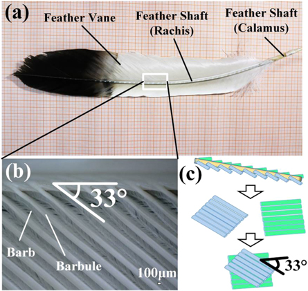
Figure 2. The (a) morphology of eagle feather. (b) Angle between feather shaft and barbules and (c) bionic structure model of eagle feather.
Download figure:
Standard image High-resolution image3.2. Microstructure
Figure 3 shows the effect of corrosion process on surface morphology of short carbon fibers and the fracture morphology of short carbon fiber reinforced epoxy resin composite with various carbon fiber contents. Compared with the uncorroded carbon fibers in figure 3(a), the corroded carbon fibers exhibited a large number of deep furrows in figure 3(b). The rougher morphology provided more contact area for short carbon fibers, which enhanced the wettability effectively and increased the bonding strength between carbon fiber and matrix.

Figure 3. Microstructure of (a) uncorroded and (b) corroded carbon fibers. Fracture morphology of composite with various carbon fiber contents of (c) 0.1 wt.%, (d) 0.2 wt.%, (e) 0.3 wt.%, (f) 0.4 wt.%.
Download figure:
Standard image High-resolution imageFrom figures 3(c)–(f) it can be observed that the carbon fibers existed in epoxy resin matrix. The carbon fibers bonded tightly with the epoxy resin matrix, which disclosed the feasibility of composite preparation method and effectiveness of acid corrosion of carbon fibers. The relatively excellent bonding state between carbon fibers and matrix provided the materials base for high mechanical strength of composites.
3.3. Phase component
Figure 4 shows the phase identification of epoxy resin matrix and short carbon fiber reinforced epoxy resin composites with various carbon fiber contents. As indicated, compared with the epoxy resin matrix, the solidified composites only consisted of C. XRD result confirmed the existence of carbon fibers in composite from the point view of phase identification. Combined with figures 3 and 4, short carbon fiber reinforced epoxy resin composites were prepared successfully. The excellent wettability and distribution direction of short carbon fibers in epoxy resin matrix played an important role in mechanical properties. Therefore, based on characteristics of microstructure and phase components, mechanical properties including tensile strength and impact toughness of short carbon fiber reinforced epoxy resin composites were investigated to disclose the optimal carbon fiber content.
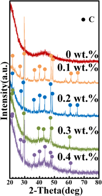
Figure 4. Phase identification of short carbon fiber reinforced epoxy resin composites with various carbon fiber contents.
Download figure:
Standard image High-resolution image3.4. Mechanical strength
Figure 5 shows the average values of tensile strength and impact toughness of short carbon fiber reinforced epoxy resin composites. The tensile strength value of matrix was 19.82 MPa. Tensile strength values of CF1-CF4 were 25.40 MPa, 31.52 MPa, 23.35 MPa and 18.46 MPa, respectively. With the increase of carbon fiber content, tensile strength increased first and then decreased. CF2 possessed the highest tensile strength (31.52MPa), which was almost 1.6 times as great as epoxy resin matrix (19.82 MPa). The impact toughness value of matrix was 4.05 kJ m−2. Impact toughness values of CF1-CF4 were 4.87 kJ m−2, 5.95 kJ m−2, 4.37 kJ m−2 and 3.63 kJ m−2, respectively. With the increase of carbon fiber content, impact toughness increased first and then decreased. CF2 possessed the highest impact toughness (5.95 kJ m−2), which was almost 1.47 times as great as epoxy resin matrix (4.05 kJ m−2). The addition of carbon fibers into epoxy resin matrix was an efficient method to affect mechanical strength of carbon fiber reinforced epoxy resin composites.
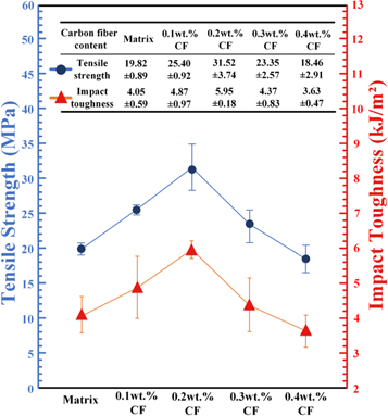
Figure 5. Tensile strength and impact toughness of short carbon fiber reinforced epoxy resin composites with various carbon fiber contents.
Download figure:
Standard image High-resolution image3.4.1. Tensile fracture morphology
Identification of fracture appearance was beneficial to analyze the mechanical properties of carbon fiber reinforced epoxy resin composites. As shown in figure 6, variation of carbon fiber contents significantly affected fracture appearance of carbon fiber reinforced epoxy resin composite. The rough fracture appearance of resin matrix, CF1 and CF2 with cracks can be observed clearly in figures 6(a)–(c). With the increase of carbon fiber content, the number of cracks increased clearly. Moreover, micro streamline cracks spread along with the loading direction on the fracture appearance of CF3, as shown in figure 6(d). Compared with figures 6(a)–(d), few numbers of cracks existed in figure 6(e). Fractured appearance of CF4 was relatively smooth, as shown in figure 6(e). Carbon fibers were pulled out and broken, which improved the tensile strength effectively. Combined with figure 5, CF2 possessed the highest tensile strength.

Figure 6. Tensile fracture appearance of short carbon fiber reinforced epoxy resin composites with various carbon fiber content (a) 0 wt.%, (b) 0.1 wt.%, (c) 0.2 wt.%, (d) 0.3 wt.%, (e) 0.4 wt.%, (f) tensile test samples and (g) tensile resistance mechanism.
Download figure:
Standard image High-resolution imageFrom the analysis of microstructure, it could be found that variation of carbon fiber content influenced the tensile strength. The fiber reinforcement mechanism was explained in figure 6(g). In the initial stage of tensile progress, a matrix crack was halted by the carbon fibers. Then the fiber debonding started. The friction between fiber and matrix prevented the crack propagation. The increasing load broke the fibers. Finally, the broken fibers were pulled out against the friction of the matrix. The existence of carbon fibers reinforced the tensile strength of composites, leading to the higher tensile strength than that of epoxy resin matrix. The relative high carbon fiber contents increased the agglomeration degree of carbon fibers, decreased the dispersion uniformity and bonding strength between fibers and matrix in CF3 and CF4. Based on the moderate carbon fiber content, CF2 owned the highest tensile strength value.
3.4.2. Impact fracture morphology
Figures 7(a)–(e) show the impact appearance of epoxy resin matrix and carbon fiber reinforced epoxy resin composites with 0.1 wt.%–0.4 wt.% carbon fibers. Impact appearance of carbon fiber reinforced epoxy resin composite is significantly affected by variation of carbon fiber content. The impact fracture surfaces of epoxy resin matrix were relatively smooth, which can be attributed to the typical brittle fracture behavior. The smooth mirror-like surface with micro-flow cracks existed in figures 7(b)–(e). Moreover, carbon fibers were pulled out and broken. Carbon fiber debonding and breakage improved impact toughness of the composites.

Figure 7. Impact fracture appearance of short carbon fiber reinforced epoxy resin composites with various carbon fiber content (a) 0 wt.%, (b) 0.1 wt.%, (c) 0.2 wt.%, (d) 0.3 wt.%, (e) 0.4 wt.%, (f) impact test samples and (g) impact resistance mechanism.
Download figure:
Standard image High-resolution imageAs shown in figure 7(g), the fiber was gripped by the matrix before impact. With the increase of impact load, a crack appeared and halted by the fiber. Interfacial shearing and lateral contraction of carbon fibers resulted in fiber debonding and crack extension. During impact process, the broken fiber was pulled out against the frictional grip of the resin matrix, which improved the impact toughness of the composites. The relative high carbon fiber contents led to the agglomeration of fibers and decreased the impact toughness between fibers and matrix. Therefore, CF3 and CF4 exhibited the relative low impact toughness. Due to the suitable carbon fiber content, CF2 owned the highest impact toughness value.
Combined with figures 3 and 4, liquid-phase oxidation improved the bonding strength between carbon fibers and resin matrix effectively, which provided a foundation base of excellent mechanical properties of carbon fiber reinforced epoxy resin composites. The carbon fiber reinforced resin composite with 0.2 wt.% carbon fiber content owned the highest mechanical properties, which was treated as optimal content for preparation of bionic composite and analyze availability of bionic structure design.
3.4.3. Characterization of bionic composites
Figure 8(a) show directed arrangement of carbon fibers in the bionic composites. The angle between two adjacent layers of carbon fiber was about 66°, which was the similar to the angle between the barbules on both sides of the feather shaft in eagle feather and proved the feasibility of bionic design.

Figure 8. Arrangement direction of carbon fibers in adjacent layers of bionic composite, (c) tensile fracture and (d) impact fracture of bionic composite and (e) comparison of tensile strength and impact toughness of bionic composites and traditional composites.
Download figure:
Standard image High-resolution image
It could be seen from figure 8(b) that the average value of the tensile strength and impact toughness of the bionic composites. The tensile strength value was 38.920MPa, which was about 1.29 times than that of composite without bionic structure (30.143 MPa). The impact toughness value was 190.573 kJ m−2, which was about 1.038 times of the composite without bionic structure (183.660 kJ m−2). The enhancement of mechanical properties proved the validity and feasibility of bionic eagle feature structure design.
Compared with the composite without bionic structure, besides the layered structure of carbon fiber, no fish-scale cracks existed in figures 8(c) and (d). The reasons can be attributed to the carbon fiber direction angle and the angle between carbon fibers and the force direction, which increased pulling and breaking difficulty of carbon fibers in the matrix and enhanced the tensile strength and impact toughness of bionic composite. The fiber angle tended to increase the load during fracture and promote disordered crack tip behavior. The crack path tortuosity was caused by the crack branching of the main crack, which leaded to the crack propagation in the different layers. Cracks of the composite without bionic structure propagated in the direction of the fibers. Fibers with high mechanical properties promoted crack propagation. Correspondingly, the rougher fracture morphology existed in composite with bionic structure. The crack deviated by the fibers with different angles in adjacent layers and changed the crack propagation direction in other layers. Therefore, the bionic composite exhibited high mechanical properties via fracture and drawing out of carbon fiber and crack deflection of bionic arrangement and layered structure.
4. Conclusions
In this work, inspired by eagle feather structure, bionic carbon fiber reinforced composites with high mechanical properties including tensile strength and impact toughness were prepared successfully. The conclusions are described as follows:
- (1)The angle between feather shaft and barbules of eagle feather was beneficial for its mechanical strength, which provided an effective bionic model for design and preparation of bionic short carbon fiber reinforce epoxy resin composite. Liquid-phase oxidation increased the wettability of carbon fibers, which enhanced the bonding strength between carbon fibers and resin matrix and provided a foundation base for mechanical properties of composites.
- (2)Variation of carbon fiber content significantly affected tensile strength and impact toughness of composite. With the increase of carbon fiber content, the tensile strength and impact toughness increased first and then decreased. The composite with 0.2 wt.% carbon fiber owned highest mechanical properties. Based on the optimal carbon fiber content, the bionic composite realized the angle arrangement of carbon fibers, which realized angle of adjacent layers in bionic model.
- (3)The eagle feather structure with two adjacent layers of carbon fiber at an angle of about 66° can improve the mechanical properties of carbon fiber reinforced epoxy resin composites. Compared with the traditional vertically arranged carbon fiber reinforced epoxy resin composite, the composite with the bionic structure has higher tensile strength and impact toughness. Debonding and breakage of carbon fiber were the mechanical enhancement mechanisms of carbon fiber reinforced epoxy resin composites. The fracture and drawing out of carbon fiber and crack deflection were mechanical mechanism of bionic composite. Considering of the economy, efficiency and high mechanical properties, carbon fiber reinforced resin composite via aforesaid method can be widely used in improvement of tensile strength and impact resistance of carbon fiber reinforced resin composite. Advantage such as low cost, lightweight and high strength of composite give it opportunities to be applied in industrial production.
Acknowledgments
The authors also wish to thank the reviewers and editor for kindly giving revising suggestions.
Data availability statement
All data that support the findings of this study are included within the article (and any supplementary files).
Disclosure statement
No potential conflict of interest was reported by the authors.
Funding
This work was supported by the Project of National Key Research and Development Program of China (2018YFA0703300, 2018YFB1105100, and 2018YFC2001300), the National Natural Science Foundation of China (51822504, 91948302, 91848204 and 52021003), Key Scientific and Techno-logical Project of Jilin Province (20180201051GX), Program for JLU Science and Technology Innovative Research Team (2017TD-04) and China Postdoctoral Science Foundation (2020M670845).