

Abstract
Bubble electrospinning technology can be used for mass production of nanofibers, it has been widely used in polymer electrospinning such as PVA, PVP and PAN, but there are no reports on the preparation of composite phase-change nanofibers by this method. In this paper, the transparent solution 1(PEG was put into formic acid according to the mass fraction of 60%) was mixed with the transparent solution 2 (PA66 was put into formic acid according to the mass fraction of 15%) according to the mass ratio of 15:85 , 25:75 , 35:65 and 45:55 to prepare four kinds of spinning solutions. And the pure PA66 nanofiber membrane(PNM) and PA66/PEG composite nanofiber membrane(PGCNM) were fabricated by the improved bubble electrospinning device on the basis of bubble electrospinning device invented by He Jihuan etc Also we analyzed their surface microstructure and tested their mechanical properties, thermal properties and molecular structure. The lower the content of PA66, the smaller the adhesion granular matter on the nanofiber surface and the thicker the diameter of the nanofiber, but the surface of the nanofiber is more smooth. The PGNCM appeared double absorption peak at 1515.5 cm−1 and 1642 cm−1 and existed weak absorption peak at 3298 cm−1 ∼ 3302 cm−1. The tensile strength and the elongation at break of the PGNCM was less than that of the PNM. The hot decomposition process of the PGNCM was composed the melting exothermic process of PEG and PA66. When the mixed ratio between PA66 and PEG was 15:85, the decomposition rate of residues between 210 ∼ 310 °C was the fastest.
Export citation and abstract BibTeX RIS

Original content from this work may be used under the terms of the Creative Commons Attribution 4.0 licence. Any further distribution of this work must maintain attribution to the author(s) and the title of the work, journal citation and DOI.
Introduction
In recent decades, Polyethylene glycol (PEG), also known as polyethylene oxide poly (PEO) or polyoxyethylene (POE), refers to the ethylene oxide oligomers or polymers [1, 2]. PEG has good compatibility with water, methanol, benzene, methylene chloride and so on. At present, lots of scholars have done many applied researches on it, which is widely used because of its phase transition characteristics. It also has latent heat, so more and more people want to apply it on the water, air and air conditioning, and it can store and release heat in the scope of the smaller space [3–5]. Ahmet Sar et al [6] combined PEG with natural clay to form thermal insulation building materials for energy absorption, PEG600 can still absorb 28 ∼ 32 J g−1 of the thermal energy at 10.9 °C. Bingtao Tang et al [7] combined PEG with SiO2 to form a stable phase-change temperature storage material, in which the latent phase-change heat of PEG reaches 148 ∼ 152 J g−1.
Compared to other nanotechnology [8–10], such as chemical vapor deposition and needle electrospinning technology, bubble electrospinning is the most effective method for fabrication of functional nanofibers whose diameters can range from a few to several hundred nanometers under high voltage [11–13]. Bubble electrospinning technology can also be used for mass production of nanofibers [14–16], it has been widely used in polymer electrospinning such as PVA, PVP and PAN. For example, Li et al have fabricated ZrCl2/PVP, ZrCl2/PVA and ZrCl2/PAN composite nanofiber membranes by critical bubble electrospinning for high-temperature-resistant adsorption and separation [17]. Liu et al fabricated PVDF/FeCl3·6H2O composite nanofibers via bubble electrospinning and the composite nanofibers were calcined in air at 600 °C for 3 h with a rising rate of 10 °C per min to achieve dark red ɑ-Fe2O3 nanobulk which can be used as gas sensors, catalysts, electrode materials, and absorption materials [18]. Zhao et al fabricated composite silk fibroin/chitosan nanofiber membrane which can be widely used as biomedical materials because of their good biocompatibility [19]. Zhao et al developed unsmooth PS/PVP nanofibers by sudden solvent evaporation in bubble electrospinning [20]. But there are no reports on the preparation of composite phase-change nanofibers by the bubble electrospinning.
In this paper, it is the first time to prepare the composite phase-change nanofiber by bubble electrospinning method. The transparent solution 1(PEG was put into formic acid according to the mass fraction of 60%) was mixed with the transparent solution 2 (PA66 was put into formic acid according to the mass fraction of 15%) according to the mass ratio of 15:85 , 25:75 , 35:65 and 45:55 to prepare four kinds of spinning solutions. And the pure PA66 nanofiber membrane(PNM) and PA66/PEG composite nanofiber membrane(PGCNM) were fabricated using the improved bubble electrospinning device on the basis of bubble electrospinning device invented by He Jihuan etc Also we analyzed their surface microstructure and tested their mechanical properties, thermal properties and molecular structure.
Materials and methods
Nylon 66(PA66) Resin Particles(Molecular Weight is 10485 , Guangzhou Youtuo Polymer Materials Co.Ltd)were used in our experiment without any further treatment; the sample was stored at room temperature, and its alcoholysis degree was 98.0 ∼ 99.0%. Polyethylene glycol(PEG) (Molecular Weight is 20000 , Jinan Kaijun Chemical CO.Ltd), served as an additive, and were used as received. Formic Acid (Puyang Huaqiang Chemical CO.Ltd), served as an solvent.
As shown in figure 1, the gas is continuously blown into the spinning solution and the bubbles form and rupture on the liquid surface of the spinning liquid, as a result, forming numerous fine droplets which are like that from the spinning needle. Under the high voltage static electricity, the droplets are pulled and extended into ultra-fine nanofibers. The bubble electrospinning device was first invented by He Jihuan et al He Jihuan et al introduced a copper wire at the bottom end of the reservoir, which was connected with the positive electrode of the high-voltage static electricity.
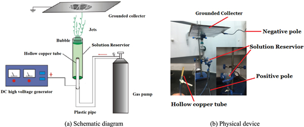
Figure 1. Improved bubble electrospinning device.
Download figure:
Standard image High-resolution imageWe found that the existing self-assembled device was complicated in the actual operation process. In order to simplify the operation, the self-assembled bubble electrospinning device in our experiment made some improvements. The copper wire is converted into a hollow copper pipe and the upper end of the hollow copper pipe is connected with the liquid storage tank, while the lower end of the reservior is connected with the plastic pipe, as a result, the hollow copper pipe is conductive and ventilating. The grounded aluminum foil(collector) covered with the fixed insulated flat sheets.
The bubble generated during the spinning, whose surface tension σ can be expressed in the form equation (1):

where Pi and Po are the air pressures inside and outside the bubble respectively, and r is bubble's radius. In order to form nanobubbles, a small external force is required to overcome the surface tension [21]. Therefore, multiple adjustments must be made during the actual spinning process to control the external force.
The electrospun nanofiber morphology was analyzed using a S4800 cold field scanning electron microscope (SEM, Hitachi S-4800, Tokyo, Japan). The experimental operation process followed the manufacturer's guidelines. To determine the diameter distribution of nanofibers, 100 fibers from 30 SEM images were chosen for diameter distribution analysis using Image software (National Institute of Mental Health, Bethesda, MD, USA).
The molecular structure of the electrospun nanofiber was analyzed by fourier transform infrared spectrometer (Nicolet5700, Tianjin Ruian technology Co.Ltd). Tensile property was measured by the mechanical property testing machine (INSTRON-3365 Material Testing Machine, Shanghai HengZhun Instrument technology Co.Ltd). The nanofiber membrane of 5 samples were sheared as a rectangle with a width of 1 cm and a length of 5 cm, as required. The thickness of the fiber membrane was measured using a micrometer by selecting 5 different location. All experimental data given in this paper were the averages of at least 5 measurements. In the test, the holding length was 30 mm and the testing speed was 20 mm/min. Load at maximum extension of composite nanofiber membranes is tested by universal material testing machine. The calculation formulas of tensile strength and elongation at break are shown in equations (2) and (3) respectively.


Firstly, PEG was put into formic acid(solvent) with a temperature of 60 °C according to the mass fraction of 60%, and the mixture was then magnetically stirred on a heating magnetic stirrer (DF-101S, Huikang Instrument Inc., Suzhou, China) until a transparent solution 1(TS1) was obtained. Secondly, PA66 was put into formic acid(solvent) with a temperature of 60 °C according to the mass fraction of 15%, and the mixture was then magnetically stirred on the same heating magnetic stirrer until a transparent solution 2 was obtained. At last, the transparent solution 2(TS2) was mixed with the transparent solution 1(TS1) in four mass ratio of 15:85 , 25:75 , 35:65 and 45:55 using a magnetic stirrer to stir evenly for 3 to 4 h to obtain four kinds of final composite transparent solution(CTS15, CTS25, CTS35 and CTS45).
The bubble electrospinning process was similar to that of our previous publications. In our experiment, the PA66 nanofiber membrane and PA66/PEG composite nanofiber membrane were fabricated using the improved bubble electrospinning device by applying a positive voltage of 20 kV over a distance of 15 cm between the solution reservior and the collector. After only 20 min of bubble electrospinning, the uniform nanofiber membrane was deposited on the aluminum foil. The composite nanofiber membranes prepared by CTS15, CTS25, CTS35 and CTS45 were recorded as PGCNM15, PGCNM25, PGCNM35 and PGCNM45.
The rheological properties of the solution was measured by rheometer (NDJ-8s Digital Viscosity Rheometer, Shanghai Ni Run Intelligent Technology Co.Ltd). Pipette was used to take 1 ml solution whose rheological curve was obtained from rheometer, then the viscosity of the solution under zero shear force was finally calculated.
The thermal properties were analyzed by differential scanning calorimeter(DSC-500A, Shanghai Innuo Precision Instrument Co.Ltd) and thermal analyzer(TG-DTA 812, Beijing Henven Technology Co.Ltd). The PA66/PEG composite nanofiber membrane was fully cut into pieces. No more than 5 mg of the chopped sample placed in a furnace filled with nitrogen was analyzed by differential scanning calorimeter under the condition from room temperature to 300 °C at a heating speed of 2.5 °C min−1 or thermal analyzer under the condition from room temperature to 600 °C at a heating speed of 10 °C min−1. The calculation formulas of thermal enthalpy is shown in equation (4).

Results and analysis
Viscosity value of Spinning Solution
The viscosity values under zero shear force of the spinning solution were shown in table 1. As can be seen from table 1, When the ration of PEG increases, the viscosity value under zero shear force of the PA66/PEG/Formic acid composite spinning solution decreases gradually, which is beneficial to the draft of the spinning solution under the high voltage electrostatic, but the curing molding is slow due to the increase on the content of formic acid.
Table 1. Viscosity value under zero shear force of spinning solution.
| Solution | Viscosity value under zero shear force/Pa·s |
|---|---|
| CTS45 | 2.106 |
| CTS35 | 1.932 |
| CTS25 | 1.6834 |
| CTS15 | 1.6709 |
| TS1 | 1.192 |
| TS2 | 2.437 |
Morphological characterization
EM illustrations for different nanofiber membranes are given in figure 2. The surface morphology of the different nanofiber membrane was clearly seen in figure 2. The red box in figure 2 represent the nanofiber with average diameter. The average diameters of nanofibers on different membranes are list in table 2.

Figure 2. SEM illustrations for different nanofiber membranes.
Download figure:
Standard image High-resolution imageTable 2. The diameter of nanofiber on the different membranes.
| Samples | Average Diameter nm−1 | Maximum Diameter nm−1 | Minimum Diameter nm−1 | Standard deviation (σ) nm−1 | Confidence Interval nm−1 |
|---|---|---|---|---|---|
| PNM | 112.82 | 223.1 | 78.2 | 19.6 | ±4.6 |
| PGCNM45 | 209.3 | 442.1 | 139.8 | 38.9 | ±9.7 |
| PGCNM35 | 923.4 | 1742.1 | 480.3 | 145.6 | ±35.2 |
| PGCNM25 | 1318 | 1815.6 | 800.7 | 191.3 | ±47.4 |
| PGCNM15 | 1299 | 1839.9 | 539.8 | 201.1 | ±52.5 |
Combined with figure 2 and table 2, it can be seen from figure 2(a) that the diameter of the nanofibers on the PA66 nanofiber membrane is the smallest. From figure 2(b) we can found that the surface of the nanofiber membrane was mostly network intersecting and porous with less granular material, however, figure 2(c) showed that the number of particles adhered to the fiber length direction increased significantly, which was not very uniform. From figure 2(d) and figure 2(e) we can clearly see that the nanofiber diameter is much larger than that of figure 2(b) and figure 2(c), but the particle adhesion decreased significantly. This is because the content of PEG which has high molecular weight continue to increase, the selected high voltage static electricity in the spinning process cannot produce high draft for all PEG polymers.
It also can be seen from figure 2 that when the mixed ratio between PA66 and PEG was different, the surface morphology of the nanofiber membrane was quite different. The surface of PA66 nanofiber membrane was smooth. When the mixed ratio between PA66 and PEG was 45:55, the nanofiber diameter was smaller, but the surface of the membrane continues to appear granular which were more at intersections. When the mixed ratio between PA66 and PEG was 35:65, there were more particles and exists larger nanofiber diameter on the membrane surface. When the mixed ratio between PA66 and PEG was 25:75 and 15:85, the particles attached to the surface of the nanofiber decreased and the diameter of the nanofiber became thicker, but the surface of the nanofiber became more and more smooth. This showed that the content of PEG is in a critical state in the spinning process of this study and the critical draft mixed ratio between PA66 and PEG is at 30:70.
Molecular structure analysis of the Nanofiber membrane
The infrared spectra of the PA66/PEG composite nanofiber membranes were given in figure 3. The infrared spectra of PA66 and PEG were given in figure 4.

Figure 3. IR spectrum of PA66/PEG composite nanofiber membrane.
Download figure:
Standard image High-resolution image
Figure 4. IR spectrum of PA66 and PEG.
Download figure:
Standard image High-resolution imageDue to the number of C–H group in PA66 and PEG was more than 4, there were plane oscillation absorption band near 6945.5 cm−1, 1378 cm−1 and 868 cm−1. The double absorption peaks of composite nanofiber membrane at 1515.5 cm−1 and 1642 cm−1 were synthesized by the stretching vibration of H–C=O in formic acid at 1718 cm−1 ∼ 1722 cm−1, the elastic vibration of O=C—NH in the secondary amides of PA66 macromolecule at 1514 cm−1 ∼ 1517 cm−1 and 1641 cm−1 ∼ 1643 cm−1, and the characteristic absorption peak of water molecules in formic acid at 1642 cm−1. There appeared strong absorption peaks around 846 cm−1 and 938 cm−1, the monomer of ethylene glycol in PEG macromolecules auto-polymerized to form a ring functional group - ETO (Ethylene Oxide), which also promoted the weak absorption peak of the composite nanofiber membrane at 3298 cm−1 ∼ 3302 cm−1, while the characteristic absorption peak at 3298 cm−1 ∼ 3302 cm−1 was the overlap of the two strong absorption peaks of hydrogen bond and amide bond in the macromolecule.
Tensile properties of Nanofiber membrane
The tensile properties of different nanofiber membranes were shown in table 3. It can be seen from table 3 that the breaking strength and the elongation at break of PA66/PEG composite nanofiber membrane was less than that of PA66 nanofiber membrane.
Table 3. Tensile properties of nanofiber membranes.
| Samples | Breaking strength/MPa | Elongation at break /% |
|---|---|---|
| PNM | 4.98 | 37.6 |
| PGCNM45 | 3.86 | 30.3 |
| PGCNM35 | 2.57 | 9.6 |
| PGCNM25 | 2.96 | 17.1 |
| PGCNM15 | 3.19 | 18.2 |
When the mixed ratio between PA66 and PEG was 35:65 , the minimum breaking strength of composite nanofiber membrane was about 2.57 MPa. This is because that there were large particles attached to the surface of the nanofiber membrane, which increased the difference of the breaking strength of the nanofiber. When the mixed ratio between PA66 and PEG were 25:75 and 15:85, the breaking strength and the elongation at break of the composite nanofiber membrane close to each other, but compared with PA66 nanofiber membrane, there was a certain gap. The reason for this result is that when the diameter of the nanofibers becomes thicker, the density arranged between them will decrease and the uniformity of the nanofiber membranes may decrease. When the mixed ratio between PA66 to PEG was 45:55 , there was a little difference on the breaking strength and elongation at break between the composite nanofiber membrane and PA66 nanofiber membrane. This is because the larger mixed ratio of PA66 and the fine nanofiber spinning and the improved uniformity of the nanofiber membrane caused by the fine nanofiber.
Thermal properties of composite Nanofiber membrane
DSC curves of different composite nanofiber membranes were shown in figure 5. The vertical coordinate unit of figure 5 was mW. From figure 5 we can see that the thermal decomposition process of the composite nanofiber membrane can be divided into two stages which were heat release of PEG and PA66 in the melting process respectively. The melting temperature of PEG from all the composite nanofiber membranes ranged from 45 °C to 105 °C, and the melting temperature of PA66 from those nanofiber composite membranes ranged from 215 °C to 255 °C. But the heat flow peak in the process of PEG melting had slightly differences. For example, when the mixed rate between PA66 and PEG was 15:85 , the heat flow peak of the nanofiber composite membrane was about 57.5 °C, and the heat flow peak of other mixed rations of the nanofiber composite membrane were about 69.8 °C. The released heat of PA66/PEG composite nanofiber membrane with different mixed ratios in two stages was shown in table 4. When the mixed ratio of between PA66 and PEG was 15:85 , the heat released of PEG melting accounts for the largest percentage of the total heat released, while the heat released by PEG melting of other mixed ratios was much smaller.

Figure 5. DSC of PA66/PEG composite nanofiber membranes.
Download figure:
Standard image High-resolution imageTable 4. Heat release of PA66/PEG composite nanofiber membranes in the melting process.
| Samples | Testing weight mg−1 | PEG heat release/J | Thermal Enthalpy/(J mg−1) | PA66 heat release/J | Thermal Enthalpy/(J mg−1) | Total heat release/J |
|---|---|---|---|---|---|---|
| PGCNM45 | 4.59 | 122.9 | 26.78 | 284.9 | 62.07 | 407.8 |
| PGCNM35 | 3.58 | 136.3 | 38.07 | 237.1 | 66.23 | 373.4 |
| PGCNM25 | 2.73 | 284.2 | 104.1 | 123.9 | 45.38 | 409.1 |
| PGCNM15 | 3.97 | 487.2 | 122.72 | 136.2 | 34.31 | 623.2 |
According to the heat release and testing weight of PA66/PEG composite nanofiber membrane, the thermal enthalpy was also shown in table 4. From table 4 we can found that the thermal enthalpy of composite nano-fiber membrane increased with the increase of PEG content. The thermal enthalpy of PGCNM15 at the first phase between 45 °C and 95 °C is 122.72 J mg−1, which is close to 138 J mg−1 (The thermal enthalpy of PEG). So the other composite nanofiber membrane's thermal enthalpy is less than 122.72 J mg−1. At the second phase, the thermal enthalpy of PGCNM15 was 34.31 J mg−1, which is close to 58.98 J g−1 (The thermal enthalpy of PEG).
The variation of residues with temperature after thermal decomposition of PA66/PFG nanofiber composite membranes with different mixed ratios were shown in figure 6. It can be seen from figure 6 that the residues after thermal decomposition gradually decrease with the increase of the temperature, and they are decomposed into monomer caprolactam or monomer ethylene glycol and their respective oligomers, which account for only about 3%. When the mixed ratio between PA66 and PEG is 15:85 , the residue decomposed rapidly between 210 °C ∼ 310 °C, but the residue mass of the other three mixed ratios remain barely changed.

Figure 6. Thermogravimetric analysis of PA66/PEG composite nanofiber membrane.
Download figure:
Standard image High-resolution image
Conclusion
When PA66 and PEG were blended in different proportions, the morphology and structure of the nanofiber membrane surface ertr also significantly different. When the mixedratio of PA66 and PEG was 35/65 , the particles attached to the surface of nanofibers were the most, when the PA66 content continues to decrease, the diameter of the nanofiber becomes thicker, but the surface of the nanofiber becomes more and more smooth. Double absorption peaks were observed at 1515.5 cm−1 and 1642 cm−1, strong absorption peaks at 846 cm−1 and 938 cm−1, and weak absorption peaks at 3298 cm−1 and 3302 cm−1 of the nanofiber composite membrane. The tensile fracture strength and elongation at break of the nanofiber composite membrane were both lower than that of the pure PA66 nanofiber membrane. The thermal decomposition process of composite nanofiber can be divided into two stages, respectively was melting process heat release of PEG and PA66, their enthalpy value was closely related to the ratio of PA66 to PEG, when the ratio of PA66 to PEG was 15:85 , the residue decomposed rapidly between 210 °C ∼ 310 °C, but the residue quality of the other three proportions basically remain unchanged.
Acknowledgments
Lei Zhao and Jumei Zhao are co-first authors of the article. The work is funded by Integration Platform of Industry and Education of Jiangsu Higher Vocational Education (Jiangsu Vocational Education 2019. No 26), the project supported by scientific research fund of Yancheng Polytechnic College(ygy2008), Jiangsu High Vocational College Academic Leaders High-end Research and Training. The work is also funded by Deeply Intergrated Training Platform of Industry and Education of Jiangsu Higher Vocational Education(Jiangsu Higher Education 2016. No 19), Qing Lan Project of Jiangsu Colleges and Universities for Young Academic Leaders(Jiangsu Teachers' letter (2020) No. 10), the Integration Platform of Industry and Education of Jiangsu Higher Vocational Education(Grant number: Jiangsu Vocational Education 2019. No 26), Jiangsu Province Higher Vocational Education High-level Major Group Construction Project-Modern Textile Technology Major Group.
Data availability statement
The data that support the findings of this study are available upon reasonable request from the authors.