
Abstract
In this study, construction of conductive and biocompatible three-dimensional nickel scaffolds (NiF) with electrodeposited chitosan (CS) for tissue engineering. The scaffolds were characterized by scanning electron microscopy (SEM), mechanical testing, water absorption, retention capacity and conductive sensitivity. Three-dimensional nickel scaffolds with electrodeposited chitosan (NiFC-n) exhibited uniformly filling structure on their surfaces and the inner structure and good mechanical property. When the versatile NiFC-n sensors were attached to different deformation, they could detect a variety of motion signals. MTT assay, Cells were stained with carboxyfluoresceinsuccinimidyl ester (CFSE) assay, apoptosis experiment and cell culture experiment results showed that NiFCn had good biocompatibility. The results indicated that the NiFC2 had a low immunogenicity, and can promote cell proliferation and support cell adhesion. This work provides a safe and feasible electrodeposition method to construct conductive and biocompatible three-dimensional nickel scaffolds with electrodeposited chitosan for tissue engineering. Therefore, NiFCn had potential application as biomaterials that may contact with real time measurement of rehabilitation for tissue engineering.
Export citation and abstract BibTeX RIS

Original content from this work may be used under the terms of the Creative Commons Attribution 4.0 licence. Any further distribution of this work must maintain attribution to the author(s) and the title of the work, journal citation and DOI.
1. Introduction
Peripheral nerve injury is a common clinical problem in the world. It often leads to perpetual disabilities in damaged regions, severely impacts the life quality of patients, and induce huge burdens in terms of social economy [1]. If the nerve defect is extensive and can't be directly seamed, nerve bridge is required. Even if autologous nerve graft is used as the clinical standard [2], relevant problems such as size mismatch between donor nerve and damaged nerve, lack of donors and malfunctions of donor nerves, still exist [3]. Therefore, people have developed the substitutes for autologous nerve graft [4].
Chitosan, a cationic polysaccharide composed of β-(1,4)-linked2-deoxy-2-amino-d-glucopyranose units, is derived from chitin. Chitosan has been applied extensively in the fields of wound dressing, drug delivery carriers and tissue engineering scaffolds [5–8], due to its remarkable properties including biocompatibility, biodegradability, pH-response, gel-form ability and antimicrobial activity [9]. Previous research has proven that chitosan can facilitate the adhesion, migration and proliferation of Schwann cells and the growth of nerve axons, and can prevent the growth of fibrous cells and the formation of neuroma [10–12]. Because of these merits, chitosan has been used for transplantation materials with microspheres, sponges, filaments and intraluminal gels [13].
Electrical signals, as one of the most important biological factors, can control cell metabolic activity, including cell adhesion, proliferation, differentiation and secretion of cytokines, especially at nerve and myocardial cells [14–16]. Therefore, an important aspect of well-functionalized scaffolds for nerve regeneration is their ability to conduct electricity. Conductive polymers, such as polypyrrole (PPy), polyaniline (PANI) and poly(3,4-ethylenedioxythiophene) (PEDOT), which exhibit excellent electrical and optical properties, have been explored in a number of biomedical applications [17–23]. However, these polymeric conductive materials are all 2D and few 3D conductive polymeric scaffolds. The cells are cultured on two-dimensional (2D) substrates under above circumstances, which fails to reflect the essential features of cells cultured in three-dimensional (3D) microenvironment. In view of this, it would be of great importance to construct an integrated platform capable of 3D cell culture and electrochemical sensing simultaneously. However, 3D materials equipped with both excellent conductivity and biocompatibility are rarely reported [24–26].
In order to establish a 3D conductive scaffold, we recently developed a biomimetic nickel foam-based 3D scaffold for long-term cell culture. Nickel based materials have been intensively investigated and considered as good potential electrode materials due to their high chemical and thermal stability, ready availability, environmentally benign nature and relatively low cost [27]. In addition to the properties of the bulk material, nickel foam has a desirable three-dimensional network structure with large specific surface area and good electrical conductivity [28], it will be very beneficial to cell growth. Construction of conductive and biocompatible three-dimensional nickel scaffolds (NiF) with electrodeposited chitosan (CS) for tissue engineering. The scaffolds were characterized by scanning electron microscopy (SEM), mechanical testing, Water absorption, retention capacity and conductive sensitivity. Three-dimensional nickel scaffolds with electrodeposited chitosan (NiFCn) exhibited uniformly filling structure on their surfaces and the inner structure and good mechanical property. When the versatile NiFCn sensors were attached to different deformation, they could detect a variety of motion signals. MTT assay, Cells were stained with carboxyfluoresceinsuccinimidyl ester (CFSE) assay, apoptosis experiment and cell culture experiment results showed that NiFCn had good biocompatibility. The results indicated that the NiFCn had a low immunogenicity, and can promote cell proliferation and support cell adhesion. This work provides a safe and feasible electrodeposition method to construct conductive and biocompatible three-dimensional nickel scaffolds with electrodeposited chitosan for tissue engineering. Therefore, NiFCn had potential application as biomaterials that may contact with real time measurement of rehabilitation for tissue engineering.
2. Experimental section
2.1. Materials
Ni foam (1.5 mm in thickness) was obtained from Kunshan Jiayisheng Electronics Co., Ltd, (Suzhou, China). Chitosan (CH, C0831, 200–600 mPas) with a deacetylation degree of 80% and a molecular weight of 200 kDa was purchased from Tokyo Chemical Industry (TCI, Shanghai). Stainless steel wires and platinum (Pt) electrodes were customized from commercial resources in China. Rat Schwann cells (RSC96) were purchased from Shanghai Institutes for Biological Science (SIBS), Chinese Academy of Science (Shanghai, China). Eagle's alpha minimum essential medium (α-MEM), fetal bovine serum (FBS), trypsin-EDTA, penicillin-streptomycin,3-(4,5-dimethylthiazol-2-yl)-2,5-diphenyl-tetrazolium bromide (MTT)solution and CFSE cell division assay kit were obtained from Sigma Aldrich (USA). Phalloidin/DAPI viability assay kit was purchased from KeyGen Biotech Co., Ltd Dimethylsulfoxide (DMSO), acetic acid, and HCl were purchased from Sinopharm Chemical Reagent Co., Ltd (Shanghai, China). All of the chemical reagents used were analytical grade.
2.2. Preparation of nickel/chitosan scaffolds (NiFCn)
2.2.1. Preparation of nickel foam
As shown in Scheme, the nickel foam was washed by HCl (1 wt%), after washed by deionized water. Then dried and storied in the dryer.
2.2.2. Construction of nickel/chitosan scaffolds (NiFCn)
The chitosan solution was prepared by dissolving chitosan flakes in a 1 wt% HCl solution under stirring, and the undissolved residues were removed by filtration. The pH was adjusted to 5.5 by using an NaOH solution (1 wt%) [29]. Then, H2O2 (21 μl H2O2 per 100 ml stock solution) was added into the chitosan solution followed with ultra-sonication for 5 min As shown in Scheme
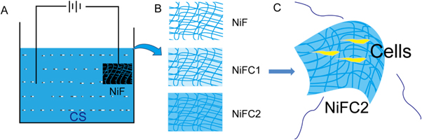
Scheme 1. A schematic representation of the NiFC-n construction procedures with a two-electrode system. The NiFC-n was harvested from the cathode. Nickel foam and DC indicates direct current.
Download figure:
Standard image High-resolution image2.3. Characterization of NiFCn
2.3.1. Structure observation by scanning electron microscopy (SEM)
The NiFCn were vacuum-dried and coated with gold. The surface and cross-sections of the scaffolds were observed by a scanning electron microscope (SEM, VEGA3, TESCAN, Czech Republic) at 20 kV.
2.3.2. Mechanical properties test
The mechanical properties of the NiFCn were measured using the universal testing machine (CMT6503, Shenzhen SANS Test Machine, China) at a tensile rate of 5 mm min−1. Each sample of NiFCn with dimensions of 10 cm length (stipes), 5 cm width were prepared for mechanical property measurement and three samples in each group were recorded (Nasir., Azmi., & Khalil., 2015) [31]. The assembled NiFCn sensors were connected to the 2450 Source Meter (Keithley, USA) to detect the current signal variation. The conductivities of the NiFCn were recorded using a 4-point probe resistivity system (RTS9, Guangzhou, China).
2.3.3. Water absorption and retention capacity
Dry NiFCn were weighed to determine the initial dry mass (W0), then dipped in deionized water and taken out at different time points. The excess water on the sample surface was gently removed by filter paper and weighed again (Wt). The water uptake ratio was calculated using the following equation 1. NiFCn statured in water were weighted (M0), then placed in a closed dryer with CaCl2. Each sample was taken out at different time points and weighed (Mt). The water retention ratio was calculated using the following equation 2 [32].


2.4. Cytocompatibility evaluation
Before cultured with cells, all kinds of NiFCn were sterilized by UV light. Cell viability was evaluated by an MTT assay. Briefly, the extracts from the NiFCn were prepared according to ISO 10993-12:2007 [29]. RSC96 cells were cultured in a 96-well tissue culture plate at a density of 1 × 10³ cells per well at 37 °C in 5% CO2 for 24 h. After that, the medium was replaced with the extracts. After incubating for 24, 48, or 72 h, the cells were treated with MTT and followed by DMSO.
Cells were stained with carboxyfluoresceinsuccinimidyl ester (CFSE) according to the manufacturer's instructions with minor modifications. Briefly, cells were dissociated, suspended in PBS at a density of 2 × 10⁶ cells/mL with 2.5 μM CFSE, and incubated at 37°C for 10 min The staining was quenched with cold medium, and cells were incubated in ice (5 min), centrifuged (1100 rpm, 5 min, 17°C), and rinsed with medium twice. Finally, the stained cells and unstained control cells were seeded in six-well tissue culture dishes at a density of 1 × 10⁵ cells/cm2. Twenty-four hours after the culture, the medium was changed to a fresh medium containing NiFCn. A stained control group containing no nanoparticles was seeded as well. For a period of 3 days, wells washed with phosphate-buffered saline (PBS), and analyzed by flow cytometry (Becton Dickinson, Franklin Lakes, New Jersey, USA) using FlowJo software.
Cells were stained with annexin V-FITC and PI in 100 μl of binding buffer for 15 min at RT. The cells were analyzed by flow cytometry using a FACS Fortessa (Becton Dickinson, Franklin Lakes, New Jersey, USA) after 400 μl of binding buffer was added without washing [33]. The absorbance values were detected at 490 nm. RSC96were seeded on NiFC2 at a density of 2 × 10⁴ cells/well in 24-well plate and cultured at 37 °C in 5% CO2. Cells cultured for 3 days were collected for morphology observation by confocal laser scanning (Leica-LCS-SP8-STED, Leica, Germany). For the observation by confocal laser scanning microscope, the cell nuclei were stained by PI and cell membrane were stained by phalloidin.
2.5. Statistical analyses
All data were expressed as mean ± standard deviation (SD). Differences between groups were determined using a one-way analysis of variance with ANOVA tests with GraphPad Software. P < 0.05 was considered statistically significant.
3. Results and discussion
3.1. Fabrication of the NiFC-n
NiFCn were fabricated as illustrated in Scheme
Table 1. Codes and parameters of the NiFC-n.
| Sample code | Materials resource or process procedure | Chitosan solution concentration (% w/v) | Performance time (h) |
|---|---|---|---|
| NiF | Nickel foam | — | — |
| NiFC1 | Low Chitosan-treated Nickel foam | ∼1 | 1 |
| NiFC2 | High Chitosan-treated Nickel foam | ∼1 | 2 |
NiF: Nickel foam; C1: Low Chitosan by electrodeposited 1 h; C2: Low Chitosan by electrodeposited 2 h.
3.2. Morphology of the NiFC-n
The SEM images of NiFC-n after freeze-drying treatment are shown in figure 1. NiFC-n were relatively regular in shape, NiF (figures 1(A), (D)); NiFC1 (figures 1(B), (E)); NiFC2 (figures 1(C), (F)). As the electrodeposition time of chitosan increased, the NiFC-n pores were gradually filled. The surface structure of NiFC-n at different magnifications are shown in figures 1(D)–(F). Obviously, NiFC-n were homogeneous and showed a porous structure which is beneficial for nutrient transportation and gas exchange [35, 36]. Therefore, compared with the scaffolds constructed by other methods, the NiFC-n fabricated by the electrodeposition process showed some advantages such as a gel-like property, tenaciously and biocompatibility [37–39].

Figure 1. SEM images (A)–(F) of the NiFC-n (n = 0, 1 and 2). Surface view (A)–(C), Higher magnification of A-C (D)–(F).
Download figure:
Standard image High-resolution image3.3. Mechanical testing of NiFC-n
The compressive stress-strain and average compressive strength curves of the NiFC-n (n = 0, 1 and 2) scaffolds are shown in figures 2(A) and (B). The compressive strength of NiF was 1.7MPa, which was relative good for scaffolds [36, 40]. The strain of NiF was about 20.5%. As the electrodeposition intensifies, the NiFC-n increases slowly. The strain of NiFC1 was about 24%; and the strain of NiFC2 was about 33%, so the scaffolds exhibited good extensibility with increased chitosan. The strength of NiFC-n decreased sharply with chitosan content, and NiFC2 exhibited the lowest strength of 0.8 MPa, which was good for nerve regeneration, so NiFC2 could satisfy the strength requirement of the tissue engineering such as nerve scaffolds [41, 42].

Figure 2. The compressive stress-strain (A) and average compressive strength (B) curves of the NiFC-n (n = 0, 1 and 2) scaffolds, and water absorption ratio (C) and water retention ratio (D) curves of the NiFC-n (n = 0, 1 and 2) scaffolds.
Download figure:
Standard image High-resolution image3.4. Water uptake and retention behaviors of NiFC-n
Figure 2(C) shows the water uptake ratio curves of NiFC-n. The water uptake ratio for all the scaffolds increased with time and reach edequilibrium around 1.5 h. All the scaffolds couldn't be dissolved in water in 12 h, indicating that the chitosan occurred in the scaffolds because chitosan is free solution. The equilibrium water uptake ratio of NiFC1 was about 50%, indicating good water absorbing capacity. Equilibrium water uptake ratio of the scaffold increased obviously with the increase of chitosan content. Moreover, NiFC2 exhibited water uptake ratio of about 56%, which was better water absorbing capacity [43, 44].
The water retention ability for biomaterials is important for its use in biomedical field [45]. Figure 2(D) shows the water retention ratio curves of NiFC-n. The water retention ratio of all the scaffold over 12 h was above 20%, so the scaffold exhibited certain water retention ability. The water retention ratio of the scaffold increased with the chitosan content for NiFC-n(n = 0, 1 and 2), mainly because the equilibrium water absorption ratio of NiFC-1 and NiFC-1 was 20% and 30%. It was observed that NiFC2 absorbed water very quickly, and water uptake reached equilibrium within the first 2 h. NiFC2 has the greatest equilibrium swelling, owing to the hydrophilicity of chitosan (CS) which contains hydroxypropyl at the C6 position of chitosan molecules [46]. NiFC2 is made up of chitosan and nickel foam, while the internal nickel foam does not absorb water, and the whole water absorption capacity is expressed by the chitosan. With the increase of chitosan content, the equilibrium water absorption of scaffolds increased significantly. The water absorption of NiFC2 was about 56%. With the introduction of Chitosan, the scaffolds exhibited tunable degradation rates by adjusting the content of chitosan, and weight remaining ratios of approximately 85% were observed for the NiFC2 (figure S1 (available online at stacks.iop.org/MRX/8/045401/mmedia)). As a result, NiFC-n exhibited suitable mechanical properties, high water uptake and water retention performance for the potential applications as biomaterial such as nerve scaffolds and tissue scaffolds.
3.5. Pressure sensor based on NiFC2 scaffolds
Under a constant voltage of 3.0 V, the folding-sensing property of the NiFC-n scaffolds was evaluated on a KickStartanalyzer system of a 2450 Source Meter [30]. To investigate the piezoresistive scaffolds of the NiFC2, a cylindrical sensor with a length of 2 cm and a width of 1 cm was used for resistance detection. Figure 3(A) shows a simple circuit test, and the NiFC2 folding sensors are connected with a LED bulb and a 1.5 V battery. NiFC2 of figure 3(B) was higher magnification of figure 3(A). As a result, NiFC2 exhibited good conductive properties which was beneficial to nerve cell regeneration. In figure 3(C), the current of the NiFC2 sensor shows no obvious change after 10 times of folding–releasing deformation. The NiFC2 sensor worked effectively after 10 times of folding–releasing deformation, suggesting excellent reliability. The dry film material NiFC1 and NiFC2, with favorable conductivity, is shown in figure S2. Tests are conducted on conductivity when the materials are buckled continuously for 50 times. Finally, the materials are not broken, and still retained the conductivity at about 6.5 × 10⁻³ S cm−1 and 4.4 × 10⁻³ S cm−1, respectively. Hence, this type of materials has favorable and stable electrical conductivity. Because of this property, this material can be applied as conductive and implantable nerve graft over the long run.
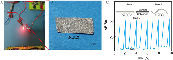
Figure 3. (A) LED circuit using NiFC2 conductive scaffolds as interconnectors. (B) Higher magnification of NiFC2 of figure 3(A). (C) Reproducibility test of NiFC2 scaffolds for 10 cycles at conductivity.
Download figure:
Standard image High-resolution image3.6. MTT and CFSE evaluation of NiFC2 in vitro
MTT assay is an effective method for the measurement of mitochondrial activity of living cells, which is broadly used for detecting in vitro cytotoxic event because most cell populations mitochondrial activity is in direct proportion to the viable cells number. Figure 4(A) shows the cell vitality of RSC96 cells incubated with extracts from NiFC2 for 24, 48 and 72 h. Cell viability was expressed as a ratio against the blank control without extracts of NiFC2. The cell viabilities of RSC96 cells in the extracts from NiFC2 were much higher than that of the control over the whole cell culture periods of 24,48 and 72 h (figure 4(A)). The viability of the cells for NiFC2 in this experiment was excellent on the whole, showing no cytotoxicity.

Figure 4. Cytocompatibility evaluation of NiFC2. (A) Cell viability of RSC96 cultured in extracts from NiFC2 for 24, 48 and 72 h. (B) CFSE proliferation assay on RSC96 with and without NiFC2.
Download figure:
Standard image High-resolution imageThe cell viabilities of RSC96 cells in the extracts from NiFC2 was evaluated by carboxyfluoresceinsuccinimidyl ester (CFSE) staining and flow cytometry analysis. The CFSE proliferation assay was carried out (figure 4(B)). In comparison, proliferation of NiFC2 group at 5.92%, 5.96% for control group, respectively (figure 4(B)). The curves demonstrating the level of fluorescence are identical for control group and NiFC2 group, indicating no significant difference in cell proliferation, and therefore, in cell viability between the different concentrations of NiFC2.
3.7. Apoptosis and the cell morphology evaluation of NiFC2 in vitro
In addition, flow cytometry experiment was applied to quantitatively determine the percentage of cell apoptosis (figure 5(A)). Annexin Vfluoresce in isothiocyanate (FITC)+ cells were considered as early-apoptotic cells (figure 5(A), Q2), while propidium iodide (PI)+ Annexin VFITC + cells were considered as late-apoptotic or necrotic cells (figure 5(A), Q3). As shown in figure 5(A), the results illustrated that NiFC2 group instigated necrosis (6.33%) as compared to the negative control (5.89%). The experimental results showed that NiFC2 group had no significant apoptosis/ necrosis compared to control group.

Figure 5. (A) Flow cytometry experiment was applied to quantitatively determine the percentage of cell apoptosis of NiFC2 group. (B) Confocal microscopy photos of cells incubated on the surface of NiFC2.
Download figure:
Standard image High-resolution image
The biocompatibility evaluation of NiFC2 was assessed using confocal laser scanning microscopy (CLSM), with phalloidin and cell nucleus into green and blue, respectively. As shown in figure 5(B), the number of cells on the surface of the NiFC2 was similar to that of the control group. The cells were spindle shaped and the nuclei were round, which were normal shape of RSC96 cells. It was proved that the cells adhered to the NiFC2 surface were living cells. Therefore, it could be considered that the biocompatibility of NiFC2 was good. This was because the NiFC2 in this article could be formed under physiological conditions, and the system does not contain any toxic substances. The raw materials used were all natural and abundant in organisms. This strategy of NiFC2 promoted the RSC96 cells differentiation (Figure S3).
4. Conclusion
In this work, we successfully constructed an electrode-posited chitosan-based nickel foam (NiFC-n) for the first time. The NiFC2 were superior in terms of their precise specifications, maintaining the nature of chitosan, good mechanical properties, good conductivity and biocompatibility. This work provides a safe and feasible electrodeposition method to fabricate chitosan/nickel foam scaffolds, which might have potential applications in the field of peripheral nerve tissue engineering.
Acknowledgments
This work was supported by the China National Special Research Program of Synthetic Biology (2018YFA0902702), the China Postdoctoral Science Fund (2020M670049ZX), Guangdong Basic and Applied Basic Research Foundation (2020B1515120018); the Natural Science Foundation of Guangdong Province (2017A030310585).
Data availability statement
The data generated and/or analysed during the current study are not publicly available for legal/ethical reasons but are available from the corresponding author on reasonable request.
Contributions
Conceived and designed the experiments: GT, XZ; Performed the experiments: ZL, KW, YL, CO, WL; Analyzed the data: GT, XZ, ZL, KW; Wrote the paper: ZL, GT, XZ. All authors read and approved the final manuscript.
Competing interests
The authors declare that they have no competing interests.
Availability of data and materials
The datasets during and analyzed during the current study are available from the corresponding author on reasonable request.
Consent for publication
All the co-authors consent to publish the work in
Ethics approval and consent to participate
This study was approved by the Research Ethics Committee of The Second People's Hospital of Shenzhen (Shenzhen, China).