
Abstract
The development of lightweight, impact-resistant and high energy dissipation materials is of great significance to reduce the hazards of explosions and impacts. Metal rubber (MR) has the characteristics of low density, high damping performance and high elasticity, which shows great potential in the field of protection. However, there are few studies on the dynamic mechanical response of MR under high-speed impact. A series of experiments were carried out to study the mechanical properties of MR. It is found that the deformation mechanism of the metal wire inside the MR determines the mechanical properties. Under quasi-static conditions, the stress-strain of MR includes an elastic stage, a softening stage and a hardening stage, and the stress-strain under high-speed impact includes an elastic stage, a softening stage and a failure stage. In addition, the smaller the wire diameter, the higher the load-bearing capacity of the MR. The damage characteristics of MR under high-speed impact are divided into expansion failure and compaction failure, which will affect mechanical performance in the failure stage. The calculated energy absorption and ideal energy absorption efficiency show that MR is a material with excellent energy absorption properties. The dynamic elastic modulus and dynamic peak stress of MR have strain rate effect and density effect. A constitutive model based on Sherwood-frost equation was established, which can precisely forecast the dynamic mechanical properties.

Original content from this work may be used under the terms of the Creative Commons Attribution 4.0 licence. Any further distribution of this work must maintain attribution to the author(s) and the title of the work, journal citation and DOI.
1. Introduction
In recent years, explosion accidents have occurred frequently, causing great harm to people. The application of impact-resistant materials has become an effective way to reduce the hazards of explosion [1–4]. In the military field, military aircraft, military vehicles and individual body armor all have extremely high requirements for the protective performance of materials [5–7]. The development of materials with light weight, impact resistance and high energy consumption has become the research focus in the field of protection [8, 9]. Metal rubber (MR) is a porous metal material. It is formed by stamping the metal wires with stretched and spiral state in a mould. Since metal rubber (MR) not only has the inherent characteristics of the selected metal wire, but also has elasticity like rubber [10–13], it is named as metal rubber (MR). MR has the characteristics of light weight, high damping performance, high elasticity and high energy consumption, and shows great potential in the field of protection [14].
At present, the researches on MR mainly focus on macroscopic mechanical properties and its formation mechanism, mechanical properties and its influencing parameters, manufacturing technique, mechanical model. Zhang et al [15] found that the macroscopic stiffness of MR is nonlinear and there are hysteresis loops during loading and unloading. They observed the internal structure of the MR through SEM and CT, and found that the transition of the contact state between the metal wires resulted in nonlinear stiffness and hysteresis loops. Tan et al [16] summarized the mechanical properties of MR under quasi-static conditions. The MR undergoes an elastic stage, a strain softening stage and a compaction stage during the quasi-static compression. Liu and Tan et al [17–19] conducted tensile and torsion tests on MR, and found that MR has excellent elastic damping properties. The mechanical properties of MR mainly depend on its material. The widely used materials include steel [18, 20, 21], aluminum [16], titanium [22–24], nickel [25], and the use of sintering and gluing technology can further improve its mechanical properties [16, 18, 22–24]. In addition, studies have shown that the porosity, relative density, and size effects also have impacts on its mechanical properties [16, 18, 22, 23, 26]. In addition to the above influencing factors, the manufacturing technique can also control the mechanical properties. Chegodaev et al [27] expanded the range of elastic damping and strength characteristics of MR through preparing the blank by the spiral winding section. Li et al [28] solved the problem of low stiffness of MR through a knitted-dapped manufacture process. It is necessary to establish mechanical models to explain and predict mechanical properties of MR. At present, the mechanical models based on the cantilever beam cell [29], friction pyramid cell [27] and helix cell [30–32] are more classic. Most literatures tend to use helix cell to establish mechanical models, because the mechanical model based on helix cell has few parameters and is convenient to use.
Hu et al [33] proposed a honeycomb model with random defects and studied its dynamic mechanical properties through experiments and finite element method. Based on the test results, Hu et al established a constitutive model that considers topological structure, random defect and strain rate effects, and it was found that the established constitutive model can accurately reflect the dynamic mechanical performance of the samples. It lays a theoretical foundation for the design and application of the honeycomb structure with random defects. This paper mainly refers to the method of Hu's paper to carry out the research on the dynamic mechanical properties of MR.
MR is mainly used in the field of vibration damping and vibration isolation, and the research on impact resistance is rarely involved. This paper studies the application of MR in the field of impact resistance, so it is of great significance to master the mechanical properties of MR under high-speed impact. Firstly, the quasi-static and dynamic stress-strain curves of MR were analyzed. Secondly, the influences of strain rate and relative density on the dynamic elastic modulus and dynamic peak stress were studied. Thirdly, the energy absorption characteristics of MR and the influence of metal wire diameter were analyzed. Finally, a constitutive model was established to predict the mechanical properties of MR.
2. Materials and methods
2.1. Materials
The MR samples in the quasi-static and dynamic tests are made of austenitic stainless-steel wire (0Cr18Ni9) with a diameter of 0.3 mm. The manufacturing process can be summarized into the following three steps: first, encircling the austenitic stainless-steel wire into a dense helix; Second, stretching the dense helix stainless-steel wire with a fixed pitch and weaving the stretched stainless-steel wire into porous base materials; Third, putting the base materials into a designed mold and applying a compression force to obtain the MR product.
In order to study the influences of relative density on the dynamic mechanical properties of MR, four groups of samples with different relative densities were designed and manufactured. The relative densities are 0.25, 0.30, 0.35 and 0.40 respectively. According to the standards of the American Society for Testing Materials (ASTM) [34], the sample used for dynamic compression is cylindrical and has a diameter to thickness ratio of 2. As shown in figure 1, the designed MR cylinder has a diameter of 40 mm and a height of 20 mm. The specific parameters of the samples are shown in table 1. The relative density in table 1 is defined as follows.


Where is the density of MR, is the density of the austenitic stainless-steel, is the porosity of MR.


Figure 1. (a) Non-molding direction of MR; (b) Molding direction of MR; (c) Magnified view of MR.
Download figure:
Standard image High-resolution imageTable 1. Process parameters of MR specimens.
| Group number | Specimen number | Mass (g) | Height(mm) | Diameter(mm) | Relative density |
|---|---|---|---|---|---|
| 1 | MR1-1 | 50.12 | 20.34 | 39.73 | 0.250 |
| MR1-2 | 50.23 | 20.31 | 39.75 | 0.251 | |
| MR1-3 | 50.14 | 20.12 | 39.75 | 0.253 | |
| MR1-4 | 50.21 | 20.21 | 39.76 | 0.252 | |
| 2 | MR2-1 | 60.12 | 20.34 | 39.74 | 0.300 |
| MR2-2 | 60.21 | 20.14 | 39.77 | 0.303 | |
| MR2-3 | 60.23 | 20.24 | 39.74 | 0.302 | |
| MR2-4 | 60.22 | 20.34 | 39.72 | 0.301 | |
| 3 | MR3-1 | 70.13 | 20.34 | 39.73 | 0.350 |
| MR3-2 | 70.12 | 20.37 | 39.72 | 0.350 | |
| MR3-3 | 70.14 | 20.24 | 39.73 | 0.352 | |
| MR3-4 | 70.22 | 20.33 | 39.77 | 0.350 | |
| 4 | MR4-1 | 80.23 | 20.42 | 39.73 | 0.400 |
| MR4-2 | 80.21 | 20.41 | 39.78 | 0.399 | |
| MR4-3 | 80.22 | 20.36 | 39.74 | 0.400 | |
| MR4-4 | 80.12 | 20.31 | 39.75 | 0.400 |
2.2. Method
Quasi-static and dynamic mechanical tests are of great value to comprehensively evaluate the mechanical properties of materials. Quasi-static mechanical tests and dynamic mechanical tests are distinguished based on strain rate. The strain rate range of quasi-static mechanical test is 10−6 s−–1 s−1, and the influence of inertial force can be ignored. The strain rate of dynamic mechanical test is greater than 1 s−1. The influence of inertial force cannot be ignored in dynamic testing, and with the increase of strain rate, the inertial effect is more significant.
As shown in figure 2, the quasi-static tests were carried out on the INSTRON-5982 material testing machine, and the loading speeds were 1 mm min−1.

Figure 2. Quasi-static compression tests of MR.
Download figure:
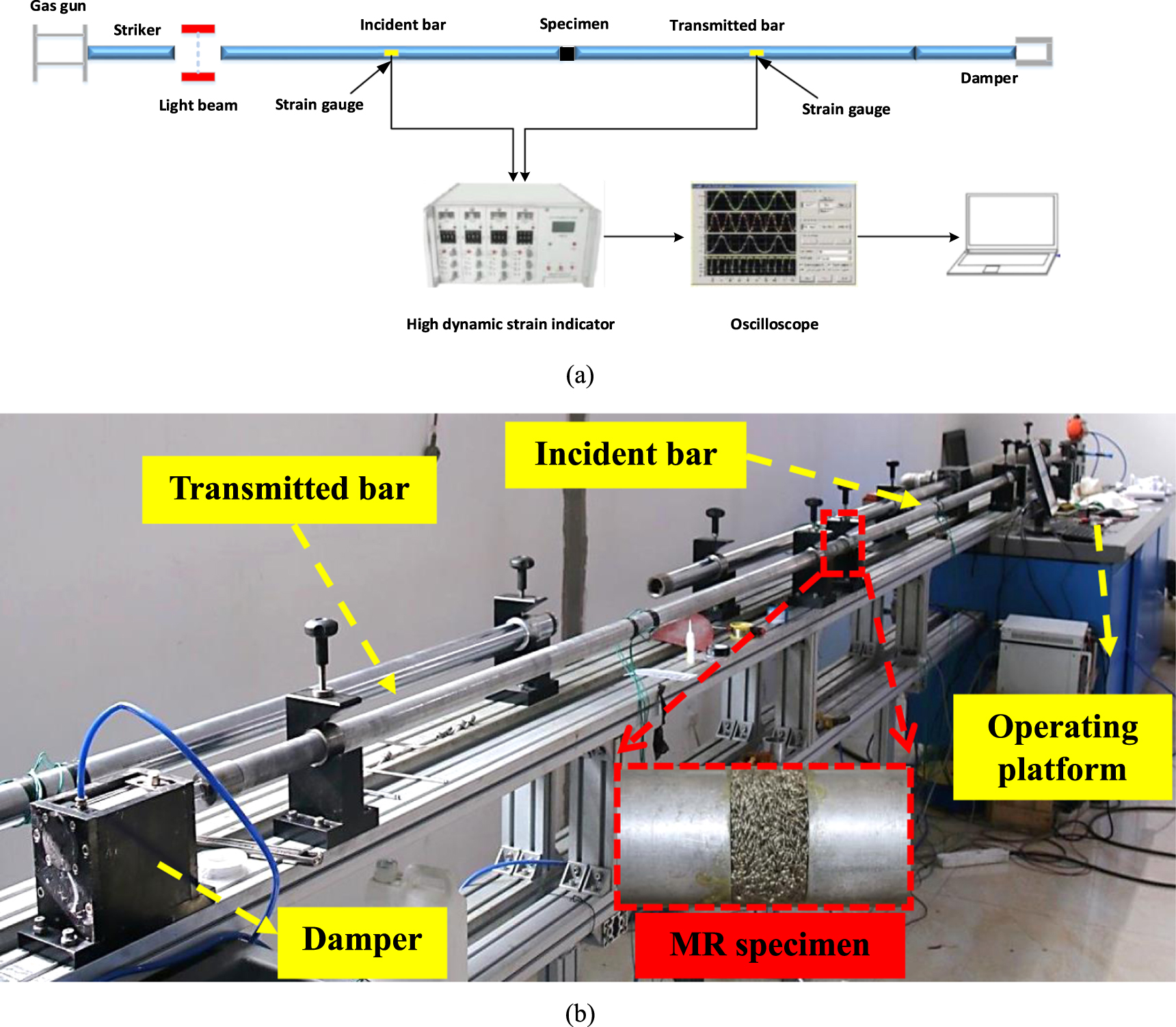
Standard image High-resolution imageSplit-Hopkinson pressure bar (SHPB) technology is an important test method for studying the mechanical properties of materials at high strain rates. The schematic diagram of the experimental device is shown in figure 3. The lengths of the striker, the incident bar and the transmitted bar are 400 mm, 2500 mm and 2500 mm, respectively. The striker, incident bar and transmitted bar are made of aluminum 7075, with a diameter of 40 mm. According to the one-dimensional stress wave theory and the classical two-wave method (5), the stress, the strain and the strain rate of the specimen satisfy the following equations.


where A, E, C are the cross-section area, the elastic modulus and stress wave velocity of the bar. are the cross-sectional area and thickness of the sample, respectively. are the incident strain signal, reflected strain signal and transmitted strain signal, respectively, measured by the strain gauges on the incident bar and the transmitted bar.


Figure 3. The SHPB test system. (a) Diagram of the SHPB device; (b) Physical picture of the SHPB device.
Download figure:
Standard image High-resolution imageIn this paper, the strain rates of different samples are controlled by different impact speeds. The impact velocities of each group of specimens 1–4 are 10 m s−1,20 m s−1,30 m s−1 and 40 m s−1, respectively. In order to ensure the accuracy of the results, each test was repeated three times and the average of the results was taken. The typical waveforms of MR are shown in figure 4.

Figure 4. Typical incident, reflected and transmitted pulses of MR (a) (b) (c) (d)


Download figure:
Standard image High-resolution image3. Results and discussion
3.1. Quasi-static mechanical properties
Figure 5 shows the quasi-static stress-strain curve of MR. The stress-strain curve can be divided into linear stage, softening stage and hardening stage. In the linear stage, the metal wires of MR are in the elastic stage, and the elastic modulus of the MR is equal to the superposition of all metal wires, so the MR is in the elastic stage. As the load increases, the MR enters the softening stage. In the softening stage, relative sliding occurs between the metal wires. When the relative sliding reaches a certain degree, the metal wire will be constrained by other metal wires, so the stiffness of MR first decreases and then increases. In the hardening stage, as the strain increases, the force between the metal wires increases, so the stress rises rapidly with the strain.

Figure 5. Stress-strain curve under quasi-static conditions.
Download figure:
Standard image High-resolution image3.2. Dynamic mechanical properties
The dynamic mechanical performance parameters of MR obtained through experiments are shown in table 2.
Table 2. MR dynamic mechanical performance parameters.
| Group number | Specimen number | Relative density | Strain rate (s−1) | Peak stress (Mpa) | Elastic modulus (Gpa) |
|---|---|---|---|---|---|
| 1 | MR1-1 | 0.250 | 1270 | 10.7 | 1.11 |
| MR1-2 | 0.251 | 1424 | 13.8 | 1.41 | |
| MR1-3 | 0.253 | 1561 | 16 | 2.15 | |
| MR1-4 | 0.252 | 1647 | 18 | 2.68 | |
| 2 | MR2-1 | 0.300 | 1178 | 14 | 1.14 |
| MR2-2 | 0.303 | 1242 | 16.3 | 1.44 | |
| MR2-3 | 0.302 | 1402 | 25.7 | 2.24 | |
| MR2-4 | 0.301 | 1592 | 35.1 | 3.00 | |
| 3 | MR3-1 | 0.350 | 1260 | 25 | 1.79 |
| MR3-2 | 0.350 | 1303 | 29.5 | 2.34 | |
| MR3-3 | 0.352 | 1468 | 41.9 | 4.17 | |
| MR3-4 | 0.350 | 1569 | 51.4 | 5.70 | |
| 4 | MR4-1 | 0.400 | 1309 | 39.9 | 2.78 |
| MR4-2 | 0.399 | 1427 | 50.3 | 3.89 | |
| MR4-3 | 0.400 | 1485 | 60.8 | 5.37 | |
| MR4-4 | 0.400 | 1701 | 84.7 | 8.94 |
3.2.1. Dynamic stress-strain curves characteristics
Figure 6 shows the stress-strain curves at different strain rates. In the initial stage, the relationship between stress and strain is linear. After stamping, the distribution of the metal wires is fixed, and there is contact between the metal wires. Under the impact loading, the metal wires contact and deform. The elastic modulus of MR under impact loading can be regarded as the superposition of the elastic modulus of all metal wires. Since the deformation of the metal wire is small and does not exceed the elastic range, the MR as a whole is in the elastic stage. The relationship between stress and strain is linear.

Figure 6. Stress-strain curves under different strain rates (a) Group 1; (b) Group 2; (c) Group 3; (d) Group 4.
Download figure:
Standard image High-resolution imageAs the load increases, MR enters the softening stage. In the softening stage, sliding occurs between the metal wires and the elastic modulus gradually decreases. Although relative sliding occurs, MR still has a certain load-bearing capacity due to the restriction between the metal wires, so the stress increases.
As the load continues to increase, the mutual restraint effect of the wires in the strain softening stage gradually reaches the limit and MR enters the failure stage. At this time, the stress reaches the maximum value, and then the metal wire produces irreversible plastic deformation. The load-bearing capacity of the MR decreases, resulting in a decrease in stress.
This paper compares the dynamic mechanical properties of MR and synthetic rubber. Figure 7 shows the dynamic stress-strain curve of synthetic rubber. Compared with synthetic rubber, it can be found that the elastic stage of MR is shorter, the softening stage is more obvious. This is caused by the deformation mechanism of the metal wires in the MR. MR is in the elastic stage only within a small strain range, and then enters the softening stage due to the relative sliding between the metal wires. Although the metal wire has relative sliding during the softening stage, it is still constrained by other metal wires, so the softening stage is more obvious, and the stress rises slowly.

Figure 7. Stress-strain of synthetic rubber.
Download figure:
Standard image High-resolution imageThe heights of the MR after impact are shown in figure 8. The heights of the MR in Group 1 decreased significantly. Due to the low relative density, the strain under different loading speeds are close to the ultimate strain, resulting in small height differences after impact. The height differences of MR in Group 2 under different impact velocities are obvious. The MR in Group 3 and Group 4 hardly changed in heights after impact.

Figure 8. The heights of MR under different impact speeds.
Download figure:
Standard image High-resolution imageFigure 9 shows two typical failure characteristics of MR after impact. Figures 9(a) and (b) respectively show expansion failure and compaction failure. As shown in figure 9(a), the height drops greatly and the cross-sectional expands outward in the expansion failure. The expansion failure means that the metal wires of the MR are dispersed under the impact and the MR expands as a whole, resulting in a decrease in the load-bearing capacity.
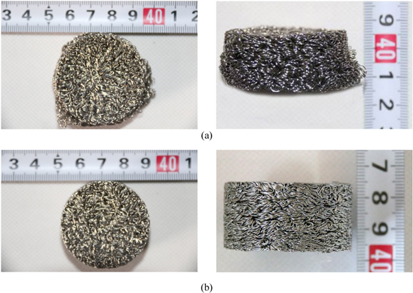
Figure 9. (a) Expansion failure; (b) Compaction failure.
Download figure:
Standard image High-resolution imageAs shown in figure 9(b), the MR with the compaction failure hardly changes. The compaction failure means that the pores between the metal wires are gradually compressed under the impact, the density of the MR increases, and the load-bearing capacity increases.
To distinguish the failure characteristics of MR mainly refer to the failure morphology. According to the height change and the damage morphology after the impact, it can be found that the MR with relative densities of 0.25 and 0.30 are expansion failure and the MR with relative densities of 0.30 and 0.35 are the compaction failure.
The failure characteristics of MR will affect mechanical performance in the failure stage. As shown in figure 6(b), the stress decline rate increases with the increase of strain rate in the failure stage. Combining the height change and damage morphology, it can be concluded that the difference in stress decline rate is due to the different failure degrees under different strain rates. As shown in figure 8, the heights of the MR in Group 2 decrease significantly with the increase of the impact speed, which indicats that the damage is more serious. Therefore, the stress in the failure stage drops faster with the increase of the impact speed. Under different impact speeds, the height changes of MR in Groups 1, 3, and 4 are small, which indicates that the damage degree is roughly the same. Therefore, the stress decline rate is the same.
3.2.2. The effect of strain rate on the dynamic mechanical properties
The relationship between the dynamic elastic modulus and strain rate of MR is shown in figure 10(a). The elastic modulus increases linearly with the increase of strain rate, showing a strain rate effect. Due to the low relative density of the MR in the Group 1 and Group 2, the elastic modulus under high-speed impact are close to the limit. Therefore, the strain rate effects of the dynamic elastic modulus are not obvious, and the slopes of the elastic modulus-strain rate fitting line are small.

Figure 10. (a) The relationship between the elastic modulus and strain rate (b) The relationship between the peak stress and strain rate.
Download figure:
Standard image High-resolution imageThe relationship between dynamic peak stress and strain rate is shown in figure 10(b). The peak stress increases as the strain rate increases, showing a strain rate effect. The damage of MR is mainly due to the irreversible plastic deformation of the metal wire. The higher the strain rate, the greater the plastic deformation of the metal wires and the more energy is required. However, due to the extremely short impact time, the MR does not have enough time to absorb energy and can only be offset by increasing the stress. Therefore, the peak stress increases as the strain rate increases. The greater the relative density, the more obvious the strain rate effect of the peak stress.
3.2.3. The effect of relative density on the dynamic mechanical properties
The relationship between elastic modulus and relative density is shown in figure 11(a). At a specific impact velocity, the dynamic elastic modulus increases as the relative density increases. The MR with high relative density has a large number of metal wires, and the elastic modulus after superposition is high. The density effect of the elastic modulus of MR becomes more obvious with the increase of impact speed. The relationship between the peak stress and relative density is shown in figure 11(b). The dynamic peak stress increases with the increase of relative density, showing a density effect. Under different impact velocities, the density effect of peak stress has no obvious difference.

Figure 11. (a) The relationship between the elastic modulus and relative density.
Download figure:
Standard image High-resolution image3.3. Energy absorption characteristics
This paper uses energy absorption and ideal energy absorption efficiency to evaluate the energy absorption characteristics of MR. The energy absorption is represented by Q which is defined as [35]:

where is any strain

The ideal energy absorption efficiency is represented by I which is defined as [36]:

where is any strain, is the maximum stress within the limits of the integral.


Figure 12 are the Q-ε and I-ε curves. As shown in figure 12, the energy absorption of MR increases as the strain rate increases. It is worth noting that the ideal energy absorption efficiency curve characteristics are different. As shown in figure 12(b), the ideal energy absorption efficiency decreases as the strain rate increases. The ideal energy absorption efficiency is the ratio of the energy actually absorbed to the energy absorbed by the material in the ideal state. In the failure stage, the stress decline rates of MR in Group 2 are different. The stress decline rate of the MR with high strain rate is fast, which leads to lower ideal energy absorption efficiency. The MR of Group 1, Group 3, and Group 4 have the same stress decline rate in the failure stage, so the ideal energy absorption efficiency increase with the increase of strain rate. The ideal energy absorption efficiency is always kept at a high level, indicating that MR has excellent energy absorption characteristics.

Figure 12. Q-ε, I-ε curves (a) Group 1; (b) Group 2; (c) Group 3; (d) Group 4.
Download figure:
Standard image High-resolution image3.4. The effect of wire diameter on the dynamic mechanical properties
Figure 13 shows the dynamic stress-strain curves of MR with wire diameters of 0.1 mm, 0.15 mm and 0.3 mm under the same strain rate. It can be found that the stress increases as the wire diameter decreases. The smaller the diameter, the more adequate the contact of the metal wires, which makes the friction between the metal wires greater. The greater the friction, the more difficult it is for the metal wires to slide relative, resulting in higher loading bearing capacity.

Figure 13. Dynamic stress-strain curves of MR with different wire diameters.
Download figure:
Standard image High-resolution image3.5. Constitutive model
The dynamic mechanical behavior of MR under high-speed impact is very complicated. In this paper, a constitutive model was established based on the Sherwood-frost equation. Sherwood-frost equation is a commonly used constitutive model for porous materials. Gao Hua et al [37] applied the Sherwood-frost equation to establish a dynamic cumulative damage model of aluminum foam under multiple impacts. On the basis of Sherwood-frost equation, Wang et al [38] established a constitutive model of expanded polyvinyl alcohol by adding relative humidity factors. The commonly used Sherwood-frost equation for porous metal materials is

where is the temperature function; is the density function; is the strain rate function; is the shape function.


3.5.1. Fitting shape function
In this paper, the stress-strain curve with a relative density of 0.25 and a strain rate of 1270 s−1 is selected as the reference curve for fitting the shape function. A polynomial fitting method is used to fit the shape function. The polynomial fitting function is shown in formula (9), and n = 10 is the number of items, σ0 = 10.7 Mpa is the peak stress of the reference curve. The fitting results are shown in table 3.

Table 3. Fitting parameter of shape function.
| A0 | A1 | A2 | A3 | A4 |
|---|---|---|---|---|
| 0.124 | 323.819 | 4.3 × 10⁵ | −9.2 × 10⁷ | 9.5 × 10⁹ |
| A5 | A6 | A7 | A8 | A9 |
| −5.7 × 10¹¹ | 2.1 × 10¹³ | −4.6 × 10¹⁴ | 5.6 × 10¹⁵ | −2.9 × 10¹⁶ |
3.5.2. Influence of strain rate and density
The relative density and strain rate have an influence on the mechanical properties of MR under high-speed impact. The density function and strain rate function are used to predict the mechanical properties of MR. By comparing the experimental data, it is found that the relationship between the dynamic peak stress and the strain rate is a linear function. The strain rate function is defined as:

where B and C are fitting parameters.
MR with different relative densities have different strain rate functions. Through further fitting, it is found that the slope or intercept of the strain rate functions and its relative density are approximately linear, as shown in figure 14. Therefore, the slope and intercept of the strain rate function are defined as:


where B and C are the slope and intercept of the strain rate function, respectively. E, D, F, G are the fitting parameters, ρ is the relative density.

Figure 14. (a) The relationship between the slope and the relative density; (b) The relationship between the intercept and the relative density.
Download figure:
Standard image High-resolution imageThe fitting results are shown in table 4. The expressions of the slope and intercept are


Table 4. Fitting parameter of shape function.
| E | D | F | G |
|---|---|---|---|
| 0.6666 | −0.14781 | −695.0585998 | 160.53951 |
3.5.3. Verify the constitutive model
The constitutive model of MR under high-speed impact calculated from formula (8)–(14) is

where is the temperature function, the test is carried out at room temperature, ρ is the relative density. The fitting parameters are as described above.


The constitutive model was verified by comparing the calculated data with the experimental data. The comparison results are shown in figure 15. Through comparison, it is found that the constitutive model can accurately predict the dynamic mechanical response of MR.

Figure 15. Comparison of calculation results with experimental results (a)Group 1; (b)Group 2; (c)Group 3; (d)Group 4.
Download figure:
Standard image High-resolution image3.5.4. Application of constitutive model
The constitutive model established is mainly used to predict dynamic mechanical properties. The dynamic mechanical properties of the MR with a relative density of 0.25 and a strain rate of 1750 s−1 was predicted. The comparison result is shown in figure 16. It can be found that the prediction result is consistent with the experimental result, which further proves the accuracy of the established constitutive model.

Figure 16. The comparison between the calculated result and the experimental result.
Download figure:
Standard image High-resolution image
4. Conclusion
Based on a series of experiments, the mechanical properties of MR were comprehensively studied. The main conclusions are as follows.
- (1)The stress-strain of MR under quasi-static compression includes an elastic stage, a softening stage and a hardening stage. The dynamic stress-strain of MR is divided into three stages: elastic stage, softening stage and failure stage. The deformation mechanism of the metal wires inside the MR determines mechanical response of the MR.
- (2)The failure characteristics of MR can be divided into expansion failure and compaction failure. The failure characteristic of MR will affect mechanical performance in the failure stage.
- (3)The dynamic elastic modulus and the dynamic peak stress of MR have strain rate effect and density effect. The energy absorption and ideal energy absorption efficiency of MR generally increase with the increase of strain rate. Since the stress decline rate of the MR in Group 2 increases with the increase of the strain rate, the ideal energy absorption efficiency decreases with the increase of the strain rate.
- (4)The smaller the diameter of the wire, the more difficult it is for the metal wire to slide relative, which makes the load-bearing capacity of the MR higher.
- (5)A constitutive model of MR under high-speed impact was established, which can accurately predict the dynamic compression mechanical properties.
Acknowledgments
The authors thank the anonymous reviewers for their excellent comments and suggestions that contributed to the improvement of this paper.
Data availability statement
The data generated and/or analysed during the current study are not publicly available for legal/ethical reasons but are available from the corresponding author on reasonable request.
Funding information
This article does not receive any funding.