
Abstract
Twin-wire indirect arc welding is a novel welding process. In this article, the anode wire was an austenite-based welding wire, and the cathode wire was an iron-based wear-resistant welding wire. Given that the two wires burn simultaneously in twin-wire indirect arc welding, a carbide-enhanced austenite-based surface layer was produced. The high-temperature wear resistance of the austenitic stainless steel was enhanced by the carbides. Results indicated enhancements in amount of reinforcing phase in the austenite-based surface layer with increasing of cathode wire feeding speed and the high-temperature friction coefficient decreased first and then increased. However, the corrosion resistance of austenite-based surfacing layer decreased slightly with increasing of amount of reinforcing phase. At low content of the reinforcing phase in the surface layer, the high-temperature wear behavior was dominated by oxidative adhesive wear, which changed to abrasive wear with the increase in the reinforcing phase.
Export citation and abstract BibTeX RIS

Original content from this work may be used under the terms of the Creative Commons Attribution 4.0 licence. Any further distribution of this work must maintain attribution to the author(s) and the title of the work, journal citation and DOI.
1. Introduction
Austenite stainless steel is widely applied in chemical, nuclear, machinery, medical, and other fields [1–3] because of its excellent high-temperature performance and formability, chemical stability, workability [4–7]. However, its low hardness and poor wear resistance restricted its application in wear-resistant environments. In general, austenite stainless steel cannot be used for important frictional moving parts. Surface welding is usually performed to produce wear-resistant coating [8–10]. Many studies on surfacing wear-resistant coatings on stainless steel layers have been conducted [11, 12]. G.R.Mirshekari [13] studied the effect of interlayers on the microstructure and wear resistance of stellite 6 coatings deposited on AISI 420 stainless steel by GTAW technique. Paulson Varghese [14] et al welded overlay coating of Inconel 617 M on type 316 l stainless steel by cold metal transfer. M. J. Tobar [15] et al used laser welding to clad of MCrAlY coatings on stainless steel. However, although this method increases the wear resistance, the corrosion resistance is difficult to consider. If suitable hard-phase particles can be added to the austenitic stainless steel matrix, not only will the hardness and wear resistance be improved, but certain corrosion resistance can also be ensured. Surfacing welding materials that are directly used to strengthen austenitic stainless steel are very scarce. In addition, due to the influence of the finished materials, substantial adjustments are difficult to undertake during the production of the surface layer. At present the commonly used methods to improve the wear resistance of stainless steel include surface modification techniques such as nitriding [16], electroless plating [17], and thermal sprayed coatings [18]. The thickness of wear-resistant layer obtained by these methods is generally very thin. Although the nitriding improves the wear resistance of stainless steel, it also increases the brittleness of the material surface, and the method requires high environmental conditions, and it is easy to occur the edge effect [19, 20]. The electroless plating has shortcomings such as short bath life, slow plating speed and high cost, so it is not suitable to practical production. The thermal spray coating has a loose structure, and the bond of the coating and the workpiece is not reliable [21, 22], while the twin-wire indirect arc welding uses the metallurgical combination of the surfacing layer and the workpiece to achieve a stable bond.
Twin-wire indirect arc welding is a novel arc welding process [23, 24]. In welding, two wires are connected separately to the anode and cathode of the DC power supply [25]. The arc is ignited between the twin wires, and the arc heat and droplet heat are used to form a molten pool [26]. Shi et al [24] found that the arc shape of twin-wire indirect arc welding was mainly controlled by current through the combination of experiment and simulation calculation. Cao et al [27] found the melting speed of the twin-wire indirect arc welding wire could be adjusted by the arc length, which was more flexible than the traditional GTAW. Wu et al [25, 28] found the twin-wire indirect arc welding are the simultaneous melting of the two wires during welding, lower heat input to the base material, and higher deposition efficiency. Thus, twin-wire indirect arc welding is suitable for surface welding. There are at least three remarkable characteristics in the application of twin-wire indirect arc welding in surfacing welding. One is the high cladding efficiency due to the simultaneous melting of two welding wires, the other is the low heat input, and the third is that the composition of surfacing layer can be changed by adjusting the coordination of two different welding wires. Specific to prepare carbide-enhanced austenitic stainless steel surfacing layer with twin-wire indirect arc welding, one welding wire melts the austenitic stainless steel welding wire, while another welding wire melts the wear-resistant surfacing welding wire during welding. The droplets melted by two welding wires form a wear-resistant surfacing layer after solidification in the molten pool. An austenitic stainless steel-based surfacing layer with different reinforcing phase contents can be obtained by adjusting the welding process. In this article, the novel welding method was applied to produce austenite-based stainless steel surfacing layer with different carbide contents. The corrosion resistance and high-temperature wear resistance of the surface layers at different cathode wire feeding speeds were studied.
2. Experiment
Based on previous studies [23], bypass-coupled twin-wire indirect welding could not only have the advantages of twin-wire indirect arc welding but also had a wider process window. Therefore, the former welding process was adapted in this study (figure 1). Twin wires were separately connected to the anode and cathode, and the workpiece was connected to the cathode of the power source. During welding, the anode welding speed was fixed; that is, the total welding current was fixed. The distribution between the twin-wire indirect arc current and workpiece current was altered by adjusting the wire feeding speed of the cathode wire. In this study, the anode wire was an ERNiCrMo-3 austenite stainless steel wire, and the cathode wire was a 964-G hard-facing welding wire. The composition of the base material and welding wire are listed in table 1. The welding parameters are provided in table 2.
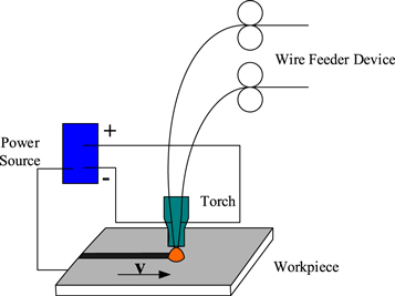
Figure 1. Schematic diagram of the bypass-coupled twin-wire indirect arc welding.
Download figure:
Standard image High-resolution imageTable 1. Compositions of the base material and welding wire.
| C | Si | Mn | P | S | Cr | Ni | Ti | Mo | Fe | Nb+Ta | V | |
|---|---|---|---|---|---|---|---|---|---|---|---|---|
| Q345B | 0.16 | 0.25 | 1.50 | 0.015 | 0.014 | 30 | — | 5 | — | rest | — | — |
| ERNiCrMo-3 | 0.009 | 0.06 | 0.03 | 0.007 | 0.001 | 22.5 | 64 | 0.18 | 9 | 0.26 | 3.58 | — |
| 964-G | 0.9 | 0.2 | 0.9 | — | — | 8.0 | rest | 3.0 | 0.2 |
Table 2. Welding parameters.
| Anode wire feeding speed(m min−1) | Cathode wire feeding speed(m min−1) | Welding current (A) | Arc voltage (V) | Shielded gas | Distance from nozzle to workpiece(mm) |
|---|---|---|---|---|---|
| 12.00 | 0.00 | 316 | 32.2 | Ar | 14.00 |
| 2.00 | |||||
| 4.00 | |||||
| 6.00 | |||||
| 8.00 |
During the surface welding, the data acquisition modules NI-9203 and NI-9201 were used to measure the welding current and voltage between the anode wire, cathode wire, and workpiece and determine the change relation between these values and the total welding current. After the surface layer was obtained, cross-section samples were cut using an electrospark wire-electrode cutting machine. Then, the cross-section samples were ground using sandpapers of 60–1500# and polished by the diamond polishing agent with particle size of 0.25 μm. After the mechanical polishing, the samples were electrolytically polished in 10% oxalic acid solution for 1 min with a current density of 1 A cm−2.
After the metallographic samples were obtained, the samples were observed using the KEYENCEVHX-500F digital microscope to determine the microstructure. Then, the distribution of elements was detected using the TM4000 scanning electron microscope (SEM) and Bruker Quantax75 energy dispersive spectrometer (EDS).
The Vickers micro-hardness of the joint was measured by a digital micro-hardness tester (HVS-1000A) with a load of 0.98 KN and loading time of 15 s. Total 5 points were taken on each sample cross section for hardness test, the highest value and lowest value were removed, and the average of another three values was taken as the hardness value of the sample.
X-ray diffraction (XRD) patterns were recorded using the DX-2700 X-ray diffractometer at a scanning rate of 0.02°/s. The samples were mechanically thinned to 80 μm. Thin foils with diameter of 3 mm were punched from the slices and then electropolished to 30 μm. Finally, twin-jet thinning was conducted, and samples for the TEM were obtained. Transmission electron micrographs, including the selected area diffraction (SAD) and bright-field (BF) images were taken with the EM-002B operated at 120 kV.
The intergranular corrosion sensitivity was detected by PARSTAT 2273 electrochemistry tester, and the polarization curves were plotted. According to the standard process [29], double-loop electrochemical potentiokinetic reactivation (DL-EPR) testing was performed with a three-electrode system, in which the saturated calomel electrode (SCE) was used as the reference electrode (RE), and the platinum mesh electrode was used as the auxiliary electrode (AE). The test was carried out in a solution of 0.5 mol l−1 H2SO4 + 0.01 mol l−1 KSCN, and the testing environmental temperature was maintained at 25 ± 1 °C by an electric heating water bath at constant temperature. In the experiment, the sample was first immersed in the solution for 10 min to obtain a stable corrosion potential. Then, the anodic polarization scan was applied at 1.67 mV s−1. When the passivation potential reached 300 mV (SCE), a reverse scan to the corrosion potential was immediately performed at the same scanning rate. The DL-EPR detected the activation current Ia and reactivation current Ir, and value Ra = Ir /Ia was the criterion for the EPR. A high Ra value represents high intergranular corrosion sensitivity. Ir is the highest anodic current of reverse scanning, and Ia is that of forward scanning.
The high-temperature wear performance of the surface layers was detected by a high-temperature wear tester at 406.6 °C. In the test, the spinning speed was 200 rpm, the testing time was 30 min, the load was 1000 g, and the friction temperature was 406.6 °C. The morphology after the wearing of the surface layers was observed by a laser scanning confocal microscope and a scanning electron microscope, respectively.
3. Results and discussion
Figure 2 shows the welding current and arc voltage under different cathode wire feeding speeds. Variations in the current and voltage at fixed anode wire feeding speed and altered cathode wire feeding speed are also shown. With the increase in the cathode wire feeding speed, the total welding current first decreased slightly and then slightly increased. The indirect arc current increased gradually, the direct arc current decreased slowly, and the percentage of indirect arc current increased.

Figure 2. Welding currents and arc voltages under different cathode wire feeding speeds.
Download figure:
Standard image High-resolution imageFigures 3 and 4 display the macro morphology of the surface layers under different cathode wire feeding speeds. The penetration and width of the welds are calculated in figure 5. The calculation results show that with the increase in the cathode wire feeding speed, the weld width increased significantly, and the excess weld metal first increased and then decreased. The penetration was not consistent with the previous results. The penetration first decreased slightly and then increased significantly, but the increasing penetration was 'finger-like' [30], which was disconnected with the reinforcement, and the weld toe was poorly fused.
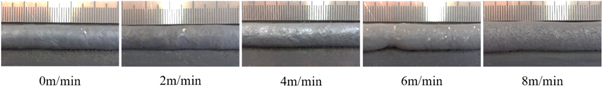
Figure 3. Weld formation under different cathode wire feeding speeds.
Download figure:
Standard image High-resolution image
Figure 4. Cross-sectional weld formation under different cathode wire feeding speeds.
Download figure:
Standard image High-resolution image
Figure 5. Cross-sectional dimensions of welds under different cathode wire feeding speeds.
Download figure:
Standard image High-resolution imageFigure 6 shows the change in the alloy element content in the surface layers under different cathode wire feeding speeds as obtained by the EBS map scanning. The contents of Ni, Cr, and Mo declined continuously, but the content of Fe increased continuously. This phenomenon is due to the fact that with the increase in the cathode ferrite-based wire feeding speed, the proportion of Ni, Cr, and Mo in the austenite stainless steel wire decreased, thereby increasing the proportion of the hard facing wire in the deposited metal. The Nb content increased first and then stabilized because the anode wire feeding speed remained unchanged. When the cathode wire feeding speed increased, the proportion of the twin wires in the weld increased, and the dilution rate of the base metal decreased [23, 25]. Therefore, the Nb content was not high at the beginning, and the Nb contents in the anode and cathode welding wires were similar. As the dilution rate of the base metal decreased, the Nb content first increased and then stabilized.
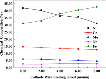
Figure 6. Chemical compositions under different cathode wire feeding speeds.
Download figure:
Standard image High-resolution imageFigure 7 shows the hardness of surface layers with different cathode wire feeding speeds. When the cathode wire feeding speed was 0 m min−1, only the anode wire melted to form austenitic-based surfacing layer strengthened by solid solution, so the hardness was lower than other surface layers [20, 31]. With the increase of the cathode wire feeding speed, the hardness first increased and then stabilized. This was because the cathode wire feeing speed increased, the melting amount of the wear-resistant wire increased and the dilution rate of the base metal decreased [25], resulting increase the content of carbide particles in surfacing layer.
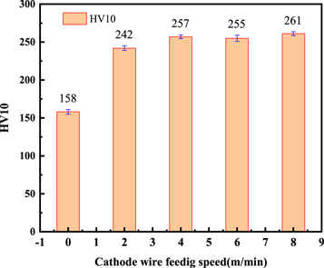
Figure 7. The hardness of surface layers with different cathode wire feeding speeds.
Download figure:
Standard image High-resolution imageFigure 8 shows the XRD patterns of the surface layers under different cathode wire feeding speeds. The patterns show obvious NbC diffraction peaks. Theoretically, diffraction peaks of chromium carbide should also exist. However, due to the overlap with other diffraction peaks, no single characteristic peak of this carbide was found. In addition, with the increase in the cathode wire feeding speed, the diffraction peak of NbC increased significantly, indicating that NbC content in the weld gradually increased [32]. As estimated from the peak area (the highest peak of the γ phase was defined as 100%), the highest NbC content (∼4.7%) was detected in the sample at cathode wire feeding speed of 8.00 m min−1, followed by the samples at 6.00, 4.00, and 2.00 m min−1 at approximately 4.1%, 3.5%, and 2.1%, respectively. This result was basically consistent with the change of microhardness.
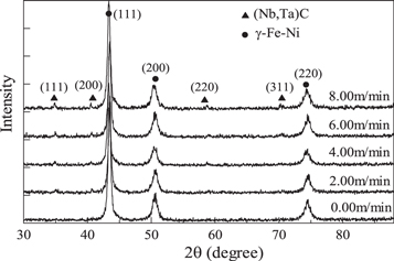
Figure 8. XRD results under different cathode wire feeding speeds.
Download figure:
Standard image High-resolution imageFigure 9 displays the results of the electronic probe map scanning of samples at 4 m min−1. In addition to NbC, which was obviously detected in the XRD, other carbides, such as chromium carbide, were obviously found. NbC and CrC had different distributions, which indicated the relatively independent existence of these carbides. Given that the XRD cannot determine the specific types of chromium carbides, the surfacing layer was analyzed by a TEM, and the result is shown in figure 10. The calibration of SAD displayed that the matrix structure in the surfacing layer was γ-Fe-Ni with a face-centered cubic crystal structure. A Cr7C3 phase also existed, except the NbC phase determined by the XRD. Visual observation of the hard phase from the two directions of [100] and [112] showed that the hard phase had a 'core' phase in the middle and another phase outside that showed a 'petal-like' radiation growth. After the selected electron diffraction analysis and diffraction spot calibration, the core phase was (Nb, Ta)C with a face-centered cubic structure, and the petal-like phase was CrFe7C0.45 with a face-centered cubic structure. This result indicated that during the metallurgical process of the molten pool, (Nb, Ta)C with higher melting point was precipitated first, and chromium carbide was used as the core of the heterogeneous nucleation. This process could increase the content of Cr-C carbide particles and refine the grains. Therefore, the NbC formed during the metallurgical process could not only increase the content of the strengthening phase but also refine the grains.
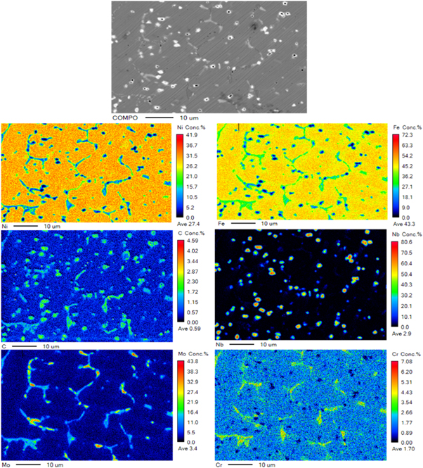
Figure 9. EPMA results of the surfacing layer under the cathode wire feeding speed of 4 m min−1.
Download figure:
Standard image High-resolution image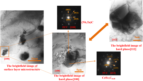
Figure 10. TEM results of the surfacing layer under the cathode wire feeding speed of 4 m min−1.
Download figure:
Standard image High-resolution imageFigure 11(a) shows the double loop intergranular corrosion curves of the surface layers under different cathode wire feeding speeds. Figure 11(b) shows the calculation of the reactivation rate (Ra = Ir/Ip ) of the surface layers under different cathode wire feeding speeds. A low Ra value implied low intergranular corrosion sensitivity, indicating higher intergranular corrosion resistance [25, 29]. With the increase in the cathode ferrite-based wire feeding speed, the melt content of the cathode wire (wear-resistant wire) in the deposited metal increased. Given that the Cr content in the wear-resistant wire was significantly low, the content of Cr and Ni in the surfacing layer continue to decrease, and the intergranular corrosion of the surfacing layer tended to be more serious. According to the standard [21], it belongs to slight sensitization when the reactivation rate Ra is less than 5, and it can pass the Streicher, Strauss, and Huey tests. It can be concluded that although the intergranular corrosion resistance of surfacing layer decreased slightly with the increase of the cathode wire feeding speed, which was still in the excellent corrosion resistance state.
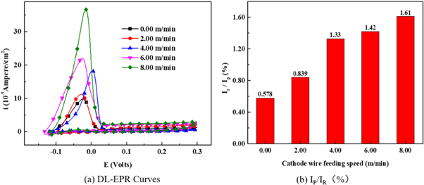
Figure 11. (a) DL-EPR results for the intergranular corrosion and (b) the calculation of the reactivation rate Ra of the surface layers under different cathode wire feeding speeds.
Download figure:
Standard image High-resolution imageFigure 12 shows the friction coefficient of the surfacing layer at 400 °C under different cathode wire feeding speeds. With the increase in the cathode wire feeding speed, the high-temperature wear resistance first increased and then decreased. The lowest friction coefficient was obtained when the cathode wire feeding speed was 4 m min−1. In order to further verify the change of the wear resistance of the surfacing layers, the wear micro morphology is shown in figure 13. Figure 13(a) shows the wear microscopic morphology of the surfacing layer with a cathode wire feeding speed of 0 m min−1, and the abrasion is the most serious. As the cathode wire feeding speed increased, the abrasion of the surfacing layers first increased and then decreased. When the cathode wire feeding speed is 4 m min−1, the wear micro morphology of the surfacing layer is shown in figure 13(c), and the abrasion is the lightest. According to the XRD result, with the increase in cathode wire feeding speed, the content of carbides increased. This phenomenon was beneficial to enhance the bone structure formed by the hard points in the surfacing layer, which was also helpful to improve the wear resistance [33]. However, high-temperature wear was affected by the oxidation resistance of the matrix and the hard phase bone structure. To deeply analyze the high-temperature wear system, the wear morphology was observed using a laser confocal microscope after 30 min of wear, as shown in figure 14. Figure 14(a) shows the wear morphology of the surface layer at 0 m min−1 cathode wire feeding speed. The wear morphology was under the condition in which no reinforcement phase existed and only austenite matrix existed. The wear morphology showed a typical oxidative adhesive wear [34]. In a high-temperature oxidation environment, an oxide film was first formed on the surface of the surfacing layer, the film square increased with the increase in oxidation time, which was beneficial to reduce the friction coefficient [35]. Therefore, the friction coefficient decreased with prolonged time. Due to the softer pure austenitic surfacing layer, the shear resistance was weak, the oxide film was discontinuous during the wear process, and the interface bonding strength was low. The oxide film fell off during repeated shearing, resulting in adhesive wear and oxidative wear [34]. The off-white area in figure 14(a) was a typical adhesion loss area. With the increase in the carbide reinforcement phase, the carbide acted as an anti-wear skeleton [35, 36], which reduced the tendency of adhesive wear and plastic deformation on the surfacing layer. This phenomenon decreased the adhesive wear characteristics. The wear morphology of the surface layer under the cathode wire feeding speed of 4.00 m min−1 had no obvious adhesive wear. The wear was relatively gentle, and no obvious furrow was found. With further increase in cathode wire feeding speed, the content of Fe element in the surface layer increased, the content of the Cr, Ni elements decreased, and the amount of oxidation film with lubrication action declined. The deciduous carbide particles caused abrasive wear, and a deeper furrow was formed on the surface of samples (figure 14(d)), and the friction coefficient began to rise again.
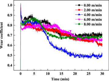
Figure 12. Wear coefficient of surface layers under different cathode wire feeding speeds.
Download figure:
Standard image High-resolution image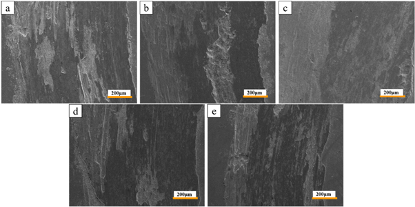
Figure 13. The wear micro morphology of surface layers with different cathode wire feeding speeds: a is 0 m min−1, b is 2 m min−1, c−1 is 4 m min−1, d is 6 m min−1, e is 8 m min−1.
Download figure:
Standard image High-resolution image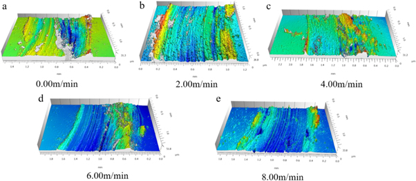
Figure 14. 3-D profile images of worn surface under different cathode wire feeding speeds.
Download figure:
Standard image High-resolution image
4. Conclusion
- 1.Twin-wire indirect arc welding could produce carbide-enhanced austenitic stainless steel surfacing layer. The use of carbides to enhance the high-temperature wear resistance of austenitic stainless steel was realized. The main carbide formed is (Nb,Ta)C and dispersed in austenite matrix.
- 2.When the cathode wire feeding speed increased, the amount of carbides in the surface layer increased, and the microhardness increased first and then stabilized.
- 3.With the increase in the cathode wire (wear-resisting wire) feeding speed, the intergranular corrosion resistance decreased slightly, and the friction coefficient first decreased and then increased.
- 4.High-temperature wear was dominated by oxidative adhesion wear when few reinforcement phases existed in the surfacing layer. This oxidative adhesion wear changed to abrasive wear with the increase in the reinforcement phase.
Acknowledgments
This work was supported by National Natural Science Foundation of China [grant number 51975331]; the fundamental research funds of Shandong University [grant number 2019HW001].
Data availability statement
All data that support the findings of this study are included within the article (and any supplementary files).