
Abstract
Joining of CuW70 composite and 0Cr18Ni9 stainless steel was successfully achieved at temperatures 1150 °C with durations from 15 to 90 min after adding a pure copper intermediate layer. Microstructure, phase composition and elemental distribution at the interfacial region were studied. The optimum joining interface with a dense microstructure was obtained at a joining temperature of 1150 °C with a duration of 60 min. Interdiffusion of atoms occurred at the interface between the tungsten-copper composite and stainless steel, resulting in formation of various compounds such as W0.6Cu0.4, Cu3.8Ni and Fe0.946Ni0.054. An iron chromium-rich layer was formed at the interface near the tungsten-copper composite side, and an island structure containing Cr, Cu, and Ni was formed near the stainless steel side.
Export citation and abstract BibTeX RIS

Original content from this work may be used under the terms of the Creative Commons Attribution 4.0 licence. Any further distribution of this work must maintain attribution to the author(s) and the title of the work, journal citation and DOI.
1. Introduction
Li et al [1] and Sang et al [2] have reported that W-Cu composites have many advantages in industrial applications, such as high arc resistance, good fusion welding resistance, high hardness, good wear resistance, low coefficient of thermal expansion, high strength of W at high temperatures and good electrical and thermal conductivities of Cu Zhou et al [3] have used W-Cu composites as contact materials for high-voltage electrical switches. A 'tail material' such as copper or a copper alloy needs to be bonded with W-Cu composite for applications in high voltage electrical switches, which has been reported by many researchers. Brochu et al [4] fabricated W-Cu composites using an electron beam welding technology with an aluminum interlayer. Chen et al [5] used friction welding to bond copper and W80Cu20 materials. Zhuo et al [6] fabricated novel W–Cu composite alloys of W60Cu40 and W70Cu30 with high hardness and high conductivity using virtue of spherical initial powders. Ding et al [7] introduced several manufacturing processes to fabricate integrated contact for the high voltage circuit breaker by bonding the W-Cu and chromium bronze. Wang et al [8] prepared CuW80/CuCr0.5 contact used in SF6 switch using vacuum sintering and infiltrating method.
Dong et al [9] pointed out that the strength of the 'tail material' is generally low, and the surface of the 'tail material' is easily corroded under severe working conditions, resulting in an increase of contact resistance and a high conductive temperature. For these reasons, these materials often do not meet the stringent requirements for industrial applications, such as those at high temperature or under corrosive and erosive conditions. As reported by Li et al [10], it is necessary to find an alternative material with a relatively lower cost to replace copper due to the high cost of copper.
Stainless steel is one of the most promising alternative materials to replace copper for this purpose. Although the W-Cu composite and stainless steel can be joined together using various methods including welding, joining is not widely used due to the existence of stress concentration caused by the large differences in the physical, chemical and mechanical properties between the W-Cu composite and stainless steel. Recently, the interfacial behaviors of composites have attracted significant interest among researchers. Tanabe et al [11] studied the diffusion bonding of Ti/graphite and Ti/diamond using a hot isostatic pressing (HIP) method and found that TiC was generated in Ti at the contact interface of a diamond after the HIP processing. Tuah-Poku et al [12] studied the different stages of transient liquid phase (TLP) bonding process using a model Ag/Cu/Ag sandwich joint associated with a simple eutectic phase diagram and found that the use of an alloy close to the eutectic composition as an interlayer material shortens the TLP process substantially. Tomoyuki et al [13] prepared tungsten/graphite joints at a pressure of 30 MPa and temperatures ranging from 1700 °C to 2000 °C for 5 min using a spark plasma sintering (SPS) technique with a SiC interlayer, and reported the reaction phases such as WC, W2C and W5Si3 at the interfaces between the W and graphite. Wu et al [14] reported that the macroscopic properties of the joints were significantly influenced by their bond strength, the presence of brittle phases at the interface and the microstructures at the interfacial region. Zhang et al [15] presented a systematic study of the differences in the microstructures and micro-mechanical properties of various Cu/Fe wave interfaces prepared by explosive welding.
Currently there are many studies on the material selection for the interlayer, the preparation processes and the microstructures of composites. However, few studies are focused on the interfacial microstructures, phase compositions and diffusion behaviors of the composites. In this paper, using copper as an intermediate layer, the joining of a tungsten-copper composite and stainless steel with an excellent interfacial bonding was successfully achieved using a conventional joining technology under a nitrogen atmosphere. The microstructure and diffusion behavior of the interfacial bonding were investigated. Because the copper in the tungsten-copper composite absorbs some of the copper in the interlayer by capillarity at high temperature, when we design the sintering of the copper-tungsten composite, we intentionally reduce the amount of copper in the alloy in order to promote the diffusion of copper, which would make more copper in the interlayer to be absorbed.
2. Experimental materials and methods
Tungsten-copper composite (CuW70) was prepared using an infiltration joining technology. The chemical composition and physical and mechanical properties of CuW70 are listed in table 1. 0Cr18Ni9 austenitic stainless steel with a dimension of Φ 8 mm × 20 mm was used as the tail material. The chemical composition of the 0Cr18Ni9 stainless steel is listed in table 2. The stainless steel and tungsten-copper composite were machined into a shape as shown in figure 1. Disc-shaped copper of Φ 9 mm × 1–2 mm was used as the intermediate layer, which was placed between the CuW70 and 0Cr18Ni9 during joining. Pure copper has the attributes of good wettability and flowability, and can fill pores and gaps in both the tungsten-copper composite and stainless steel. The chemical composition of pure copper is also consistent with that of the copper component in the WCu composite. This reduces the complexity of the chemical composition in the joining joint and makes it easier to analyze the diffusion mechanism of the joint. Sun et al [16] reported that copper, as a non-carbide-forming element, can form solid solutions with Fe, Cr, and Ni without the formation of harmful intermetallic compounds.
Table 1. Chemical composition and physical and mechanical properties of the CuW70 electrical contact.
| Chemical composition% | Physical and mechanical properties | |||||||
|---|---|---|---|---|---|---|---|---|
| Material | Cu | Impurity content | W | Density (g m−3) | Hardness HB | Resistivity/(μΩ+cm) | Conductivity IACS/% | Bending strength MPa |
| CuW70 | 30 ± 2.0 | ≤0.5 | Bal. | ≥13.80 | ≥175 | ≤4.1 | ≥42 | ≥790 |
Table 2. Chemical composition of the 0Cr18Ni9 stainless steel (weight percentage %).
| Chemical composition | C | Si | Mn | S | P | Cr | Ni | Fe |
|---|---|---|---|---|---|---|---|---|
| Content (%) | ≤0.08 | ≤1.00 | ≤2.00 | ≤0.030 | ≤0.045 | 18.00 ∼ 20.00 | 8.0 ∼ 10.50 | Bal. |

Figure 1. Assembly diagram of the stainless steel and tungsten-copper composite.
Download figure:
Standard image High-resolution imageJoining temperatures were set at 1150 °C, which is higher than the melting point of pure copper in the intermediate layer, thus the liquid copper in the intermediate layer can react with the parent materials of CuW70 and 0Cr18Ni9 effectively. The bond strength of the interfacial joint is significantly dependent on the holding time during the joining. A long heating time will cause overheating of the interface, which could result in an excessive loss of the intermediate layers, a significant deterioration of the joining of dissimilar materials, and a decrease in the bond strength. However, if the holding time is too short, the generated heat is not enough to sufficiently wet the metals and/or melt the intermediate layer, causing the uneven flow distribution of liquid and the decrease in the bond strength. Wang et al [17] reported that for austenitic stainless steel, significant grain growth will take place when the temperature is higher than 1150 °C. In this study, the optimum joining temperature and holding time will be investigated.
The assembled sample was placed in a graphite crucible and then moved slowly into the GSL 1700X tube furnace. The sample was initially sintered at 1000 °C for 15 min, and the temperature was increased to 1150 °C for 15 ∼ 90 min under the protective atmosphere of 99.9% N2. After joining, the excess stainless steel was removed from the side of the tungsten-copper composite to obtain the bonded samples of tungsten copper composite and stainless steel.
Microstructural and quantitative analyses of components at the interface between the tungsten-copper composite and stainless steel were performed using an optical microscope (XJL-03) and a field emission scanning electron microscope (FE-SEM, JSM-6700F), respectively. The phase composition in the interfacial bonding joint was analyzed using x-ray diffraction (XRD-7000, CuKα, 40 kV/30 mA) at a scanning speed of 8 °/min.
3. Results and discussion
3.1. Microstructures
Figure 2 shows the microstructures of the joint between the tungsten-copper composite and stainless steel with copper as an intermediate layer. A smooth and uniform interface can be observed between the WCu composite and stainless steel. The interface is dense and free from cracks and holes. Dotted patterns or strips of black particles can be seen in figures 2(a) and (b) (see the arrows), which are identified as the residual contaminants from polishing. The intermediate layer and interfaces are free from pores, impurities and other defects. The interdiffusion between the copper phase in the WCu composite and the intermediate Cu layer forms a gray-colored zone with a width of approximately 7 μm. From figure 2(c), the morphology of the interface between the stainless steel and the copper intermediate layer demonstrates the interdiffusion of copper and 0Cr18Ni9 stainless steel at the interface. The liquid phase of copper in the intermediate layer diffuses along the grain boundaries of the austenitic stainless steel at the high joining temperature of 1000 ∼ 1150 °C, which forms the intergranular patterns. From figure 2(c), the island structures are formed at the interface close to the 0Cr18Ni9, which is due to the wetting of the austenite grain boundaries in the stainless steel by the liquid phases of copper in the intermediate layer (see the red square).

Figure 2. Optical images of the joint. (a) microstructure at the interfaces of W-Cu/Cu/0Cr18Ni9, (b) microstructure near the W-Cu side showing the W-Cu/Cu interface, and (c) microstructure near the stainless steel side showing the Cu/0Cr18Ni9 interface.
Download figure:
Standard image High-resolution imageThe fast dissolution of atoms in austenite grain boundaries under large surface tension results in a fast 'intergranular diffusion'. The austenite grains of the stainless steel are deformed along the interface, and the microscopic surface grooves are formed at the interfaces of the grain boundaries. Due to the existence of the liquid intermediate layer and the high surface energy, the sharp grooves at the grains of the stainless steel with small radius of curvatures disappear rapidly, and the corners become rounded. The surface tension drives the liquid intermediate layers to penetrate much deeper. However, the atoms at the grain boundary have higher energy and will be dissolved quickly into the liquid intermediate layer. The groove patterns increase rapidly along the grain boundary. The contact area between the liquid intermediate layer and the stainless steel is increased significantly. This will accelerate the mutual diffusion of elements between the liquid intermediate layer and the stainless steel, improve the uniformity of the structure, and change the composition at the joint area and the stainless steel (e.g., the parent metal).
Yang et al [18] reported that metallurgical bonding of copper and stainless steel can be realized by transient liquid phase method. The joint structure is dependent on the holding time, and it is obviously divided into two layers: iron rich layer and copper rich layer. When the holding time is long enough, the structure and composition of the joint area and the stainless steel base material are homogeneous, showing an obvious transient liquid phase diffusion joint. Chen et al [19] reported that good metallurgical bonding of carbon steel and stainless steel can be achieved by using copper foil as the intermediate layer and cold-drawing and transient liquid phase diffusion method. At the copper/stainless steel interface, liquid copper diffuses along austenite grain boundary and forms isolated-island austenite distributed inside the copper matrix. The atoms of the steel and the copper liquid mutually diffuse under the action of the driving force of concentration gradient in the diffusion process. As shown in figure 2(c), a 200 μm thick dark gray stripe can be observed, and some islands can be found inside the stainless steel substrate. Cu and the elements from stainless steel alloy form a solid solution (mainly a copper and nickel solid solution). This clearly demonstrates that Cu and stainless steel have formed a strong metallurgical bond.
3.2. Interfacial diffusion behavior
Figure 3 illustrates the interfacial microstructures between the WCu composite and the intermediate layer of copper after the samples were heated at 1150 °C for various holding times. With an increase in the holding time from 15 min to 30 min, the porosity in the WCu increases as shown in figures 3(a) and (b). This is mainly due to the rapid decrease of the copper binder phases in the WCu composite. However, a dense structure of WCu can be observed at a longer holding time of 90 min, as shown in figure 3(c). At the beginning of joining with a holding time shorter than 30 min, the copper component in the WCu composite was quickly volatilized at such a high joining temperature, thereby generating the pores in the alloy. For the liquid copper in the transition layer, the holding time is too short for it to diffuse into the WCu composite. With an increase in the holding time from 30 min to 90 min, the liquid copper in the intermediate layer was diffused into the WCu composite to fill up the pores through the capillary effect. A black diffusion zone can be observed at the interface of the sample after being heated at 1150 °C for 90 min, as shown in figure 3(c). The reason is that the copper from the intermediate layer is mixed together with the copper in the WCu composite, and then it chemically reacts with the alloying elements in the stainless steel to form solid-state solutions. Some white lines in the black diffusion zone can also be observed, and they can be attributed to the formation of compounds or solid solutions from the reaction of copper with alloying elements in the stainless steel. It is reasonable to conclude that the interdiffusion of alloying elements at the interface has taken place, thereby producing a good joining at the interface. Moreover, the liquid copper fills up the pores and gaps at the interfaces between the WCu composite and stainless steel, which further increases the interfacial bonding areas.

Figure 3. Microstructures of WCu/Cu interfaces at various holding times: (a) 15 min, (b) 30 min, and (c) 90 min.
Download figure:
Standard image High-resolution imageFigure 4 shows the interfacial microstructures between the austenitic stainless steel and copper intermediate layer after the composite was sintered at 1150 °C for various holding times of 15, 30 and 90 min. It can be seen in figure 4 that more island structures are formed by intergranular diffusion with the increase in the holding time, and the diffusion is gradually extended into the parent material of 0Cr18Ni9. This is in an agreement with those shown in figure 2, and thus it further proves the excellent joining at the interface.

Figure 4. Interfacial microstructure images of Cu/0Cr18Ni9 heated at 1150 °C for various times: (a) 15 min, (b) 30 min, and (c) 90 min.
Download figure:
Standard image High-resolution imageThe EDS line scans of the tungsten, iron and chromium elements at the interface between the WCu composite and copper are shown in figures 5, 6 and 7, respectively. Tungsten diffuses into the interface with interdiffusion depths of 1.5 μm in 15 min, 7 μm in 30 min, and 19 μm in 90 min. In contrast, chromium and iron only diffuse into the interface with depths of 1.5 μm in 15 min, 9 μm in 30 min, and 25 μm in 90 min. Compared with the W element, the Fe and Cr elements diffuse much faster at the interface due to their lower melting points and higher diffusion activation energies. Liu et al [20] reported that different atoms have different diffusion behaviors across the interfaces, for examples, Fe atoms diffuse into brass for about 10 μm, whereas Cu and Zn diffuse into steel for about 2 μm, both within 2 h. Batra et al [21] reported the studies of diffusion bonding of a Cu-Cr-Zr alloy to stainless steel and tungsten, using nickel as an interlayer. They found that the width of the diffusion layer was very thin, and the intermetallic NiW2 and unreacted nickel were observed at the interfaces. This phenomenon is more obvious with an increase in the holding time. The faster diffusion rates of Fe and Cr are due to the large concentration differences of Fe and Cr elements at the interface between the WCu composite and copper, which provides the driving force for diffusion. On the other hand, tungsten and liquid copper cannot form solid solutions or intermediate phases, while Cr and Fe atoms can form solid solutions with the liquid copper, which enhances the diffusion rates. The dissolved Cr and Fe metal atoms at the interface diffuse into the liquid copper and move further into the interface of WCu through convection–diffusion.
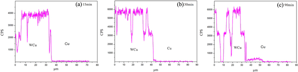
Figure 5. Diffusion scanning curve of the W element at the interface between tungsten copper and copper. (a) 15 min, (b) 30 min, and (c) 90 min.
Download figure:
Standard image High-resolution image
Figure 6. Diffusion scanning curve of the Fe element at the interface between tungsten copper and copper. (a) 15 min, (b) 30 min, and (c) 90 min.
Download figure:
Standard image High-resolution image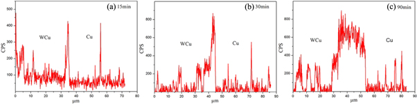
Figure 7. Diffusion scanning curves of the Cr element at the interface between tungsten copper and copper at different heating durations. (a) 15 min, (b) 30 min, and (c) 90 min.
Download figure:
Standard image High-resolution imageThe EDS line scan spectra of the copper, iron and chromium elements at the interface between the 0Cr18Ni9 stainless steel and the copper intermediate layer after sintered at 1150 °C for various holding times are shown in figures 8, 9 and 10, respectively. The interdiffusion of the Fe, Cu, and Cr metal atoms occurs at the interface, and a metallurgical bond is generated at the interface between the copper and stainless steel. During joining, the copper intermediate layer first melts, which results in a large concentration gradient between the liquid copper and the solid metals in the stainless steel. The large driving force generated from this large concentration gradient causes the interaction between the solid stainless steel and the liquid copper, and the liquid copper diffuses into the solid stainless steel. Simultaneously the solid stainless steel also dissolves into liquid copper. The diffusion processes during this process include interfacial diffusion, grain boundary diffusion, and lattice diffusion. Because there are more pores or defects along grain boundaries than at the other positions, the liquid diffusion along the grain boundaries is much faster than that along the lattices. The concentrations of Fe, Cr, and Cu elements change significantly at the interface. The Cr and Fe atoms in the stainless steel can diffuse for a longer distance into the copper intermediate layer, and then diffuse further into the interface and even into the bulk WCu composite. In contrast, there are significant differences among the concentration distributions of the Fe, Cr, and Cu elements along the interface. There is very little diffusion of Cu into the stainless steel, whereas there is a clear evidence of the diffusion of Cr and Fe into the copper. This may be related to the formation of the island microstructures in the liquid copper, as can be observed from the interfacial bonding microstructures shown in figures 2 and 4.

Figure 8. Diffusion scanning curve of the Fe element at the interface between the austenitic stainless steel and copper at different joining durations. (a) 15 min, (b) 30 min, and (c) 90 min.
Download figure:
Standard image High-resolution image
Figure 9. Diffusion scanning curve of the Cu element at the interface between the austenitic stainless steel and copper at different joining durations. (a) 15 min, (b) 30 min, and (c) 90 min.
Download figure:
Standard image High-resolution image
Figure 10. Diffusion scanning curve of the Cr element at the interface between the austenitic stainless steel and copper at different joining durations. (a) 15 min, (b) 30 min, and (c) 90 min.
Download figure:
Standard image High-resolution imageFigure 11 shows the backscattered electron (BSE) images of the interfacial region for the WCu-copper-stainless steel joint after being sintered at 1150 °C for 90 min. A diffusion zone is formed at the interface between the WCu composite and copper, as shown in figures 11(a)–(c). The main phases of the diffusion zone are composed of copper, iron, chromium, and Fe-Cr compounds. The island structure is formed at the interface between the copper and stainless steel (see figures 11(d)–(g)). With an increase in the holding time, more island structures are formed, which is consistent with the previous analysis. Liquid copper not only improves the efficient joining of tungsten-copper and stainless steel but also contributes to the formation of solid solutions or compounds in the transitional zone.

Figure 11. EDS images of the elemental distributions at the interface between tungsten-copper and stainless steel. (a), (b) and (c) are the interface and elemental distributions of the copper and WCu composite, and (d), (e), (f) and (g) are the interface and elemental distributions of the copper and stainless steel.
Download figure:
Standard image High-resolution imageIt is assumed that the formation of iron-chromium-rich layer is only caused by the diffusion of iron in tungsten matrix and the whole diffusion process is regarded as one-dimensional steady diffusion. Based on the solution of the diffusion equation for a semi-infinite body, the diffusion distance of iron can be solved using the Fick's Second Law:

where Cs is the diffusion distance, t is the time of diffusion, D is the value of diffusion coefficient. The diffusion coefficient of iron can be solved by Arrhenius equation:

Where D0 (7.12) [22] is the pre-exponential factor, Q (0.744 eV) [23] is the activation energy, R (8.314 × 10⁻³ KJ*mol−1K−1) is the gas constant, T is the absolute temperature. As shown in figure 12, the theoretical value of the thickness of iron-chromium-rich layer is consistent with the actual value. This model can be used to estimate the thickness of the solid iron layer under different holding times.

Figure 12. Theoretical and practical values of the thickness of solid iron layer.
Download figure:
Standard image High-resolution image3.3. Phase analysis
Figure 13 shows an XRD pattern of the bonding interface between the W-Cu alloy and stainless steel sintered at 1150 ° C for 90 min. The main phases at the interface between the W-Cu composite and stainless steel are composed of Cu, W, Cu0.4W0.6, Cu3.8Ni, Fe0.946Ni0.054, Fe2W, Fe and Ni. W and Cu are not dissolved into each other, however, a small amount of W can still react with Cu at such a high joining temperature of 1150 °C and a long holding time of 90 min with the presence of the various alloying elements in the stainless steel. Due to the melting of copper in the intermediate layer, which wets the interface of the stainless steel, the liquid state of Cu will combine with the solid-state metal atoms in the stainless steel to form various new bonds, thus resulting in the dissolution of some of the iron and nickel atoms at the bonding interface. The metallic bond energy of the stainless steel is significantly reduced due to the dissolution of some of its metal atoms. The liquid copper atoms are very active at the austenite grain boundary. The atoms on the surface of stainless steel will be quickly dissolved into the liquid copper, thus forming many (CuNi) solid solutions, as illustrated by the metallographic microstructures and BSE images shown in figures 11(d)–(g). Tungsten carbides and chromium intermetallics are not formed in the intermediate layer, which is mainly due to the lower joining temperature and shorter holding time. Li et al (2018) also reported the intermediate layer formation between the copper and the aluminum due to the same condition.

Figure 13. XRD result of the interface between the W-Cu alloy and stainless steel.
Download figure:
Standard image High-resolution imageBased on the above results, a schematic diagram of the reaction taking place at the interface between the WCu composite and stainless steel is shown in figure 14. The chemical phases at the interface (such as Cu0.4W0.6, Cu3.8Ni and Fe0.946Ni0.054) are composed of intermetallic compounds, which are formed from the reactions among the Cu, Fe and Ni atoms. The interdiffusions among the Cu, Ni, Fe, and W atoms at the interface take place through intergranular penetration, which reduces the atomic distance at the interface. The intergranular diffusion together with the bonding through van der Waals forces results in a good metallurgical bonding of the joint. The formation of the compound at the interface further improves the joining of the atomic bonds. However, the intermetallic compound will significantly reduce the bond strength and electrical conductivity of the joint, while a small amount of metallic compounds or intermetallic phases may increase the strength of the joint. The optimum joining interface with a dense microstructure was obtained at a joining temperature of 1150 °C with a duration of 60 min. When the heat preservation time is short (e. g. 15 min), the atomic diffusion of Cu, Ni, Fe and W cannot be fully carried out, and few solid solutions are formed at the interfacial region. If the heat is held for too long (e. g. 90 min), the grains of the solid solution can become so large that they reduce the strength of the joint.

Figure 14. A schematic diagram of the reaction at the interface between the tungsten-copper composite and stainless steel.
Download figure:
Standard image High-resolution image
4. Conclusions
- (1)The optimum joining between the W-Cu composite and 0Cr18Ni9 stainless steel is achieved by joining these two materials at 1150 °C for 60 min under the protective atmosphere of nitrogen with the application of pure copper as the intermediate layer.
- (2)The width of the transition zone in the bonding interface is approximately 1.4 mm. The new solid solution phases of Cu0.4W0.6, Cu3.8Ni and Fe0.946Ni0.054 are formed in the transition area.
- (3)The joining of dissimilar material undergoes a series of processes including diffusion and bonding, as well as the mutual diffusions of the liquid phase copper with other solid phases from the W-Cu composite and stainless steel.
- (4)The diffusion zone of the 'iron-chromium-rich layer' is formed near the side of the W-Cu transition zone, whereas the 'island structure' containing the Cr, Cu, and Ni forms near the side of the stainless steel transition zone.
- (5)The longer the joining time is, the thicker the diffusion layer, and the deeper the copper intermediate layer of the island structure into the stainless steel materials.
Acknowledgments
The authors would like to thank the Key Research Project of Science and Technology in Fujian (2014H0090), the Fujian University of Technology Fund (GY-21306), the Natural Science Foundation of Fujian province (2016 J01663), and the Key Research Project of Science and Technology in Fujian (2018H6001).
Data availability statement
All data that support the findings of this study are included within the article (and any supplementary files).