
Abstract
Ultrasonic assisted grinding (UAG) has been considered as a prominent processing method of the reaction bonded silicon carbide (RBSiC). To improve the knowledge of UAG process, both conventional grinding (CG) and UAG were used to process the RBSiC for in-depth investigation. Grinding forces, surface topographies, and subsurface damages during CG and UAG were compared. Furtherly, the ground surface was analyzed on aspects of both topographical characteristics and material removal mechanism. The results indicated that the removal of material is mainly achieved by the intersections of cracks initiated from both big SiC particles and mixture area of silicon matrix and small SiC grains. The crack propagation during UAG was more intensified due to the ultrasonic impact, which results in higher efficiency of machining RBSiC.
Export citation and abstract BibTeX RIS

Original content from this work may be used under the terms of the Creative Commons Attribution 4.0 licence. Any further distribution of this work must maintain attribution to the author(s) and the title of the work, journal citation and DOI.
1. Introduction
Silicon carbide (SiC) ceramics have been proposed and developed for the applications in aerospace, optics and automobile because of the outstanding properties, such as low weight index, moderate thermal expansion coefficient and low thermal distortion coefficient [1, 2]. Furtherly, the new composite material, which uses SiC particles as the reinforced phase, not only inherited many advantages of SiC material, but also has a series of competitive characteristics such as high thermal conductivity, high modulus, low density and low cost [3–5]. In particular, as a typical silicon carbide composite, RBSiC is one of the most popular mirror materials for the favorable properties including high hardness, low density, low thermal expansion coefficient, 100% dense, ultra-high isotropy and synthesizable large size [6–8]. With the increasing demand, the requirement for high-efficiency machining technology of RBSiC has become critical [9]. However, as a typical difficult-to-machine material, RBSiC is limited by the machining difficulties and high machining costs in the applications. In order to achieve high quality and efficient processing of RBSiC, a large number of research studies have been carried out.
For advanced ceramic manufacturing, the most effective processing method is grinding [10]. Several studies have investigated the surface integrity, surface/subsurface damage and material removal mechanisms of RBSiC processed by grinding with a diamond wheel [9, 11]. The grinding characteristics of silicon carbide have been investigated, and surface/subsurface integrity have been studied to reveal the mechanisms of material removal and damage during high removal rate grinding [12]. Xu [13] investigated the role of microstructure and associated T-curve behavior in controlling the mechanisms of material removal and damage formation during grinding and polishing. To obtain a crack-free surface at the maximum material removal rate, the selection of optimum conditions is paramount. Li [14] studied the influence of wheel speed on the surface morphology and surface roughness. For the multi-step grinding process, the sub surface damage experiment and analysis results of glass ceramics show that increasing the wheel speed can inhibit the occurrence and development of brittle fracture under the influence of strain rate and grinding temperature, leading to smaller and fewer cracks and pits, and more plastic flow.
The conventional grinding (CG) has high cost and low efficiency. Ultrasonic assisted grinding (UAG) is an effective and precise machining method combining ultrasonic vibration with traditional grinding technology [15]. As a composite machining technique, UAG is a non-thermal process, which may obtain high material removal rate (MRR) while keeping low cutting pressure, thus, leading to relatively strength degradation and low surface damage [16]. Samples ground with vibrations have been observed to have a better surface finish compared with the surface ground without vibrations, confirmed by many literature studies. The surface formation and wear behavior of grains were analyzed by E Uhlmann using both methods [15]. Comparative observations indicated that ultrasonic assisted grinding can improve the productivity of ceramics compared with conventional grinding. Also, it not only resulted in significantly higher removal rates, but also avoided additional subsurface damage [15, 17]. Moreover, the surface roughness of the sample subjected to ultrasonic vibrations was superior to the sample treated without ultrasonic vibrations, while the chip thickness and cutting forces were reduced remarkably as compared to the conventional cutting [18]. Pei studied the tool wear and cutting forces through experimental and theoretical analysis using rotary ultrasonic machining of advanced ceramics with diamond grinding wheels. The mechanism of ultrasonic grinding machining of brittle materials was analyzed, and an approach to model and predict the MRR was proposed, along with relationships between the machining parameters[19, 20]. Zheng [21] proposed a new ultrasonic assisted single particle scratch model. The results show that even with the same maximum instantaneous force, the ultrasonic assisted material removal rate is greatly improved. The relationship between ultrasonic energy, grinding parameters and surface topography was established [22]. The principle of improving ground surface quality by RUG is expounded. The results show that the grain path overlap reduced the grinding chip size and the scallop height, the grinding force is small, and the surface roughness is low. Wen [23] found that the mechanism of improving the contact performance of workpiece surface by ultrasonic assisted grinding is that the interference motion of abrasive particles makes the height distribution of workpiece surface more concentrated and the roughness density increases.
Grinding usually causes surface/subsurface damage, residual stress, and other types of damage, which have an important impact on the optical applications of ceramic components. Particularly, as RBSiC is a two-phase material consisting of the hard SiC phase and soft Si phase with high brittleness and hardness, its machining is very difficult for generating a good surface [24]. Zhang [25, 26] presented etching, fracture, and taper polishing methods to analyze the ceramic surface crack introduced by single-point diamond, and the cracking and material removal mechanisms were developed for hot-pressed alumina ceramics. Hu [27] studied the effect and optimization of ultrasonic assisted single-sided lapping of monocrystalline SiC wafer by grey relational analysis and the results show that ultrasonic assisted vibration is positively correlated with the MRR, and increases surface roughness, but the higher ultrasonic power is beneficial to restrain the increase of surface roughness. Based on the material properties and grinding parameters, an analytical model for predicting subsurface damage in rotary ultrasonic assisted face grinding is proposed and verified by experiments [28].
UAG is an effective method for ceramic manufacturing, however, it has resulted in many unresolved challenges associated with the prediction and control of the grinding damage. Therefore, it is necessary to investigate the material removal mechanism and evaluate the subsurface damage caused by grinding. In this research, the forces of CG and UAG are compared and analyzed. The surface topography and roughness are observed and measured. The surface/subsurface damages have been evaluated and characterized. The damage types and formation mechanisms are studied. The mechanism of material removal of RBSiC processed by ultrasonic assisted grinding is discussed.
2. Materials and methods
2.1. Preparation of RBSiC samples
The mechanical properties of the RBSiC samples in this study are as follows: Mohs hardness HM = 9.3 (SiC grains), Young's modulus E = 340 ± 5 GPa, Poisson's ratio v = 0.25, and density ρ = 3.06 g cm−3, fracture toughness KIC = 4.0 ± 0.1 MPa·m1/2. In order to observe the material microstructure, RBSiC sample surface was carefully polished with 20, 14, 7, 3.5, and 1 μm diamond paste successively. The polished sample surface was observed through an Olympus MX40 optical microscope, as shown in figure 1. The SiC grains and silicon bond can be clearly identified in the micrograph, the dark areas are SiC grains while the light areas silicon. The SiC grains in RBSiC all vary both in size, ranging from less than 1 μm to as large as 70 μm. Most SiC grains resulted from the originally existing grains during fabrication of RBSiC, and a small amount of SiC grains with a size in the range of several microns were the reaction products of carbon and silicon in the reaction sintering process. The large SiC grains were bonded to each other with silicon at the grain boundaries, surrounded by a two-phase mixture made up of small SiC grains and Si. By statistical calculation, the RBSiC sample consists of 71% SiC grains and the average grain size is 40 μm.
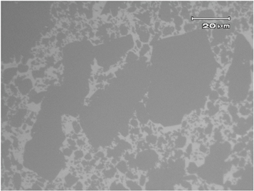
Figure 1. Microstructure of the RBSiC.
Download figure:
Standard image High-resolution image2.2. Grinding experiments
Figure 2(a) shows the experimental setup. A diamond grinding wheel was clamped in the ultrasonic tool holder, which was installed on the motorized spindle of a CNC ultrasonic grinding machine and could drive the grinding wheel to vibrate along the axial direction. The schematic of ultrasonic grinding was shown in figure 2(b). A three-axis piezoelectric dynamometer was fixed below the RBSiC workpiece to measure the grinding forces.

Figure 2. (a) Illustration of experimental setup and (b) schematic of UAG.
Download figure:
Standard image High-resolution imageThe grinding force was an important reference indicator in the ceramic grinding. As the effect of grinding speed is not obvious [29], the spindle rotational speed was chosen to be constant in the study. The effect of grinding depth and feed rate on the grinding force was researched by groups of single-factor experiments. The axial grinding force Fz is the main influence element for cracks formation and propagation [30]. Table 1 shows the workpiece dimension, the grinding tool, and the grinding parameters. The parameters with the underscore are the controlled invariants in the single-factor test.
Table 1. Grinding experiment parameters.
| Workpiece dimensions | Length | 60 mm |
| Width | 10 mm | |
| Height | 6 mm | |
| Grinding wheel parameters | Average grit size | 250 μm |
| Outer diameter | 22 mm | |
| Inner diameter | 8 mm | |
| Grinding parameters | Amplitude | 8 μm |
| Frequency | 20 kHz | |
| Spindle rotational speed | 3000 r min−1 | |
| Feed rate | 30, 50, 70, 90, 110 mm min−1 | |
| Grinding depth | 0.04, 0.05, 0.06, 0.07, 0.08 mm |
2.3. Damage assessment
After processing (under the grinding parameters with the underscore in table 1) by CG and UAG respectively, the surface topography and roughness were observed by SEM (Quanta 200, FEI) and white light interferometer (NewView5022, ZYGO, USA). The bonded interface sectioning technique was adopted to gain key information about the mechanisms of damage. The surface of the RBSiC sample after grinding was bonded to a polished silicon substrate with the resin glue (M2BOND 610). The cross-section of the sample with the protected cover was lapped and polished. A layer with a thickness of about 0.5 mm was removed to make sure that previous subsurface damage had been wiped out and a damage-free surface had been obtained. Then the cross sections were observed by an optical microscope (MX40, Olympus, Japan).
3. Results and discussion
3.1. Grinding force
Through the single factor experiment, the relations between axial grinding force and grinding depth are presented in figure 3(a). The axial grinding forces Fz increase significantly from 60 to 130 N for CG and from 20 to 60 N for UAG with the increase of the grinding depth from 0.04 to 0.08 mm. Through the single factor experiment, the relations between Fz and feed rate are presented in figure 3(b). The axial grinding forces Fz increase slightly from 110 to 130 N for CG and from 60 to 80 N for UAG with the increase of the feed rate from 30 to 110 mm min−1. Whether CG or UAG is used to process SiC, the grinding force Fz is positively correlated with the two grinding parameters studied. The reason is that the undeformed chip thickness in the axial or feed direction become thicker by the increasing feed rate and grinding depth, which leads a stronger plowing and scratching during the material removal process, resulting in larger grinding forces.
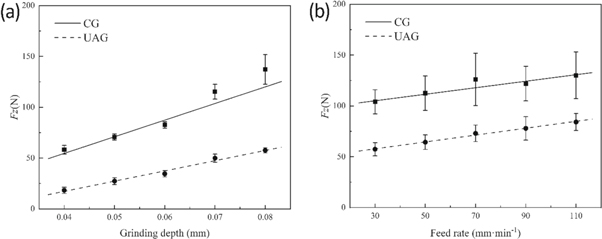
Figure 3. The effect of (a) grinding depth and (b) feed rate on grinding forces.
Download figure:
Standard image High-resolution imageBesides, the Fz for UAG are 34 to 50% smaller than CG under the same conditions, indicating the advantage of UAG in decreasing the grinding forces. One of the main reasons is the transition in the abrasive wear from attrition wear and pullout wear to micro-fracture wear in UAG, hence, the abrasive has a superior self-sharpening [31]. Meanwhile, owing to ultrasonic vibration, the contact between the tool and workpiece is inconsecutive. Thus, the grinding force is extremely small in the separation stage, resulting in the average grinding force to be smaller in UAG than that in CG [32]. Under the same limitation of grinding force, more aggressive conditions, e.g. larger grinding depth, could be used in UAG to improve the grinding efficiency.
3.2. Surface topography and roughness
The topographies of the surface were observed by SEM (figure 4). The topographies of the surface were observed. It can be found that there are two kinds of areas with different surface topographies, the fractured area and the smooth area. The fracture area of the workpiece after UAG is larger than that after CG. By EDS and interface sectioning analysis, the machining surface of large SiC grains is usually the fracture area, while the machining surface of silicon and its mixture with small SiC grains is the smooth area. The ploughing striations, which are normally found on the ground surface of ductile materials, were not observed on RBSiC surface in figure 4.

Figure 4. Surface topographies of RBSiC after processing.
Download figure:
Standard image High-resolution imageThe surface roughness of the workpieces after CG and UAG were measured by the white interferometer. Five lines were measured on each surface of the workpieces. The average value of the 5 results was treated to be the surface roughness after processing. The results of UAG (Ra = 0.658 μm, PV = 12.776 μm) and CG (Ra = 0.528 μm, PV = 10.785 μm) were roughly the same.
3.3. Subsurface damage types
Subsurface damage of workpieces observed after UAG and CG were basically the same. Two main types of subsurface damage were found: fracture and crack.
- (1)In the large SiC grains in the top layer of the workpieces, fractures were the most commonly observed, as shown in figures 5(a) and (b). Small cracks can also be observed under the fracture layer, as indicated by arrows, showing that the intersection of the cracks lead to the fractures in the large SiC grains. And the removed fractures are the main material removal mode for the SiC grains during grinding of RBSiC. In addition, both median cracks which is perpendicular or angled to the grinding surface and lateral cracks which is parallel to the grinding surface were observed, shown in figures 5(c) and (d). Some cracks even extend to the interface of the large SiC grains and the mixture area.
- (2)In the mixture area of silicon and small SiC grains, fractures were also the most commonly observed, as shown in figures 5(e) and (f). However, the fracture size in the mixture area is smaller than that in the large SiC grains. Moreover, cracks were also observed, as shown in figures 5(g) and (h). In the mixture area, the length and depth of the cracks are smaller than those in large SiC grains. In figure 5(e), it was observed that a fracture was about to form and be removed because the crack has not yet extended to the surface of the workpiece.
- (3)In the large SiC grains away from the machined surface, some cracks were observed, as shown in figures 5(i) and (h). This type of cracks was mostly straight and had no directionality. Most of the cracks were small and only existed inside the SiC grain, while some of the larger cracks penetrated through the whole SiC grain.

Figure 5. Subsurface damage of workpieces after processing.
Download figure:
Standard image High-resolution image3.4. Subsurface damage depth
In order to study the depth of the subsurface damage, Dfg, Dfm, Dc were used to represent the depth of the fractures in the large SiC grains, the fractures in the mixture area, and the cracks respectively. The cracks inside the large grains being away from the machined surface were not considered for the crack depth measurement as their formation is not regular. The average values of the damage depth for CG and UAG have been plotted in figure 6. It can be found that the average value of Dfg for UAG is slightly higher, and the average value of Dfm for UAG is slightly smaller as compared to that for CG. However, the difference of Dfg and Dfm between UAG and CG is observed to be insignificant. The average value of Dc for UAG and CG is 17 μm and 12 μm respectively, the former being 29% larger than the latter. For both UAG and CG, the depth of the cracks is always the largest, and the depth of the fractures in the large SiC grains is a little larger than the depth of the fractures in the mixture area.
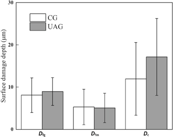
Figure 6. The subsurface damage depth of RBSiC after processing.
Download figure:
Standard image High-resolution imageIn this paper, the depth distribution of chipping pits on the surface was statistical analyzed. A surface crushing rate index Di was proposed to quantify the subsurface damage, which is defined as the ratio of the length of the accumulated value of the chipping pits which reached a given depth value and the total length of the scope of the statistical specimen in the cross-sectional direction. A randomly 2 mm long cross section is selected as the statistical specimen, and the results are shown in figure 7. From the graph it was evident indicating that during UAG the maximum depth of the chipping pit would be greater than during CG. In addition, the length of the accumulated value has the same regularity under the same chipping pit depth. The main reason for this phenomenon is that the ultrasonic vibration direction is perpendicular to the machined surface in facing grinding used in this experiment. This will cause addition damage on the machined surface. Hence, one could draw a conclusion that the subsurface damage depth of UAG were larger than the substrates machined with CG.

Figure 7. The distribution of the chipping pit on the grinding surface.
Download figure:
Standard image High-resolution image3.5. Subsurface damage formation
Malkin [33] investigated the removal mechanism of the material by using indentation fracture mechanics. A number of radial, median or lateral cracks remained on the subsurface after scratching by a diamond abrasive grain with a cutting depth. As the lateral and radial cracks intersected, the chipping pit was formed and stripped from the substrate. The median crack continued to extend to the interior of the matrix material and led to the deep subsurface damage [34]. Dou to the fractures are mainly formed by the intersection of the cracks, cracks are the main factor to form subsurface damage. According to the experimental findings from the cross-section microscopy, the subsurface cracks were divided into the following three categories, depending on their location:
- (1)Cracks in the large SiC grains in the top layer of the workpieces.In the cross-section microscopy analysis, the amount of internal cracks was analyzed on the subsurface of ground RBSiC. As shown in figures 8(a) and (b), the extrusion stress propagated the lateral cracks to intersect with the median cracks and led to the subsurface damage. From the experimental observations, it can be observed that the number of cracks in the SiC grains is higher for UAG as compared to CG, along with even depth. It is owing to the reason that the action of abrasive on the surface in UAG involves the scratch and impact effects with 20 kHz ultrasonic frequency. Thus, it is relatively simple to form surface/subsurface micro-cracks and remove material with the UAG process.
- (2)Cracks in the mixture area of silicon and small SiC grains in the top layer of the workpieces.The cracks were short and intense, and represented the principal mode of material removal in the mixture area. Figures 8(c) and (d) shows the damage topography in the mixture area. The main reason for the observed phenomenon is attributed to the weak grain boundaries, along with different strength and hardness characteristics of SiC and Si. Compared to the pure SiC material, the overall strength and hardness in the mixture area decreased, indicating that the material can be easily removed. In CG, many small cracks are introduced, and the fractures are removed smoothly under the plane movement of the wheel. A relatively flat surface is formed, as shown in figure 8(c). However, owing to the vibration of ultrasonic frequency, the movement path of diamond abrasives in the feeding direction changed from a one-dimensional horizontal line in CG to a two-dimensional sinusoidal waveform in UAG. A lot of chipping pits are formed on the surface, as shown in figure 8(d). It is clear from these findings that the total area of the chipping pits is larger in the UAG process, which is consistent with the findings from the surface roughness analysis.
- (3)Cracks in the SiC grains away from the machined surface.
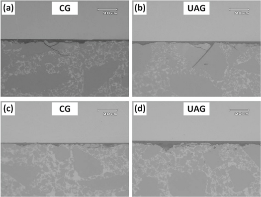
Figure 8. The subsurface damage formation after processing.
Download figure:
Standard image High-resolution imageFigures 5(i) and (j) show that the inherent defects induced during the sintering process could have resulted in such cracks. Under the squeezing effect of the diamond abrasive, a large grinding pressure can be transmitted to the defect, thus, leading to the formation and propagation of the cracks. Although very rare, this type of cracks was observed in the subsurface of RBSiC after UAG as well as CG, while their depth and length were irregular. It can be concluded that the processing methods are not the key factor in the formation of such cracks.
It can be concluded from the above observation and analysis results that the cracks in grinding process vary with different positions. No significant difference in the subsurface damage is observed between the CG and UAG processes.
3.6. Material removal mechanism
The morphology of the chipping pits is shown in figures 5(a) and (b). Under the action of the abrasive, the fractures are associated with the initiation and propagation of the cracks. A typical form of crack propagation is the expansion to the surface (smooth surface), whereas the other form is the intersection with other cracks to achieve the purpose of material removal material (sharp corner). The process of material removal during grinding is summarized as follows: by the action of the diamond grains, the material is removed through the micro crack initiation, propagation, and intersection to form the chipping pits. The removal mechanism in the SiC and Si materials is different due to the hardness difference. It is mainly divided into two types according to the location:
- (1)In the large SiC grains, there are many defects generated during the SiC sintering process, and these defects are beneficial for the formation and expansion of the cracks. As shown in figures 5(c) and (d), the extrusion stress caused by the diamond abrasives propagated the lateral cracks to intersect with the median cracks, which represents the main mechanism of material removal in the large SiC grains.
- (2)In the mixture area of silicon and small SiC grains, the intersection of the dense and short lateral cracks with the free surface of the grains leads to chipping, which achieves the removal of material, as shown in figures 5(e) and (f). As the grain size and hardness of Si are smaller than those of SiC, the micro cracks are more easily to occur in the mixture area and expand to the surface, which enhances the machinability of the mixture area.
In CG, the abrasive trajectory is in a plane defined by rotation and linear feed motion. The breakage and subsurface micro-cracks formed on the material surface layer rely on the extrusion, scratch, and shearing effects between the diamond abrasives and workpiece. However, the ultrasonic vibration direction is parallel to the axis direction in UAG. As shown in figure 9, the abrasive trajectory is different, leading to a different material removal mechanism. The ultrasonic vibration changes the direction of cutting and the actual depth of cutting. The high frequency ultrasonic vibration makes the lateral micro-crack initiation and causes a high extent of micro-crack propagation in the processing zone, thus, leading to brittle fracture [35]. Moreover, high frequency associated with the grinding tool makes the material loose and more likely to be removed. The high frequency impact is combined with extrusion, scratching and shearing effects, thus, the material removal capacity of UAG is greatly enhanced.

Figure 9. The schematic diagram of RBSiC removal process by CG and UAG.
Download figure:
Standard image High-resolution image
4. Conclusions
In this study, direct observations of surface topography and surface roughness were employed, and the axial grinding force and subsurface damage were analyzed for the different processing methods. Finally, the damage formation and material removal mechanisms of RBSiC in CG and UAG were analyzed. The following inferences can be obtained:
- (1)The surfaces obtained by UAG have a slightly inferior roughness as well as a larger number and area of the chipping pits as compared to CG, which indicates that the MMRs of UAG is higher than CG. This conclusion is also supported by the findings from the surface topography analysis.
- (2)The grinding force studies demonstrate the advantages of the UAG for grinding of the ceramic materials. The investigations exhibit up to 35% reduction in the axial grinding force for UAG, thus, it can be used to machine thin wall components.
- (3)The subsurface damage forms of RBSiC machined with UAG are basically the same as CG. Under the identical machining conditions, the number and depth of micro-cracks introduced by the unique abrasive trajectory of UAG are larger than CG.
- (4)The difference of subsurface damage formation mechanism mainly depends on the phase and location of the damage. In the large SiC grains in the top layer of the workpieces, fractures are the main damages, which are caused by the intersection of the cracks. In the mixture area of silicon and small SiC grains, the cracks in the top layer of the workpieces are short and intense. This is because the strength and hardness characteristics of this area are lower than those of SiC grains, the micro cracks easily initiate and then extend along the SiC grain boundary. The cracks in the large SiC grains away from the surface are caused by the inherent deficiencies in the sintering stage.
- (5)The material removal mechanism of RBSiC in CG is that the micro cracks initiate under the extrusion of abrasives, then the micro cracks propagate and intersect to form the removed chips. In UAG, RBSiC is not only extruded by abrasives but also impacted. The high frequency ultrasonic vibration causes a high extent of micro-crack propagation in the cutting zone, which greatly improves the material removal ability of UAG. As the grain size and hardness of Si are smaller than those of SiC, the micro cracks are more easily to occur in the mixture area and expand to the surface, which enhances the machinability of the mixture area.
Acknowledgments
The authors are grateful to the financial support from the National Science and Technology Major Project (No. 2018ZX04015001-004), the National Natural Science Foundation of China (No. 51735004) the China Postdoctoral Science Foundation (No. 2020T130076) and Joint Foundation from Equipment Preresearch and Ministry of Education (No. 6141A02022128).