

Abstract
This study aims to investigate the effect of TiN inclusions on the fracture mechanism of 20CrMnTi steel with martensite. Size of martensite packets, blocks and TiN inclusions were characterized, and the room-temperature tensile properties, impact toughness and fracture toughness were tested of 20CrMnTi steel quenched at different temperatures. The effects of TiN inclusions on the impact toughness and fracture toughness were investigated according to the Hall-Petch relationship. The results show that, TiN inclusions are high temperature stable phases which insoluble to the matrix, mostly squared in shape and dispersed. The impact toughness and fracture toughness of 20CrMnTi steel decrease with increasing sizes of the initial austenite grains, martensite packets and blocks as the quenching temperature increases. Interestingly, the TiN inclusions strongly affect the toughness of the 20CrMnTi steel in the fracture and the fine-grained sample has a better toughness. Under high-stress concentrations, TiN inclusion particles can initiate cleavage cracking.
Export citation and abstract BibTeX RIS

Original content from this work may be used under the terms of the Creative Commons Attribution 4.0 licence. Any further distribution of this work must maintain attribution to the author(s) and the title of the work, journal citation and DOI.
1. Introduction
Because of its good processability and fatigue resistance, 20CrMnTi is widely used in shafts, pistons and special parts of automobiles and aircraft. However, the purity of this steel is still a key problem that needs to be resolved because parameters related to inclusions (including their size, shape, hardness and distribution) strongly influence the performance of the steel.
In low-alloy steels, Ti and V are often added for microalloying. Two of the important reasons that Ti and V are used are their strong affinities for C and N and their tendency form microscale-and nanoscale precipitates. Meanwhile, the grain boundaries are effectively confined by precipitates of (Ti,V)(C,N) during diffusion to control the grain size in steels. This control can allow the strength and toughness of the steel to be further improved [1–3]. However, in many cases, the smelting control is not sufficiently precise, which leads to N dissolving into the liquid phase. Thus, when the ingot solidifies, a large number of high-temperature large particles such as stable TiN precipitates exist in the matrix [4, 5]. The tensile strength and impact toughness of the steel were significantly reduced due to the precipitation of large TiN inclusions [6]. TiN particles with a size larger than 1 μm reduce the toughness of steel, resulting in cleavage and brittle fracture and serious reductions in the impact toughness and fracture toughness of the material [7]. TiN particles clearly cause cleavage fracture in both ferritic-pearlite steel [8–11] and bainitic steel [12]. Most TiN particles are regular squares with sharp edges and easily nucleate and grow into larger particles near nonmetallic inclusions [11, 13, 14] (e.g., MnS, Al2O3, MgO, etc). The greater the size and quantity of these hard particles, the worse the toughness of the material.
In most studies, the induction of brittle fracture by TiN particles in ferritic steel has been gradually improved. Cleavage cracks are all initiated by TiN [15–17], and a reduction in the ferrite grain size can effectively reduce damage from large TiN particles and improve the material toughness [9, 10]. In the stress-controlled fracture process, the large-angle interface has a high resistance to cracks and plays a key role in the crack propagation process [18, 19]. The effective grain size is widely mentioned in the brittle fracture process induced by TiN particles.
Most of the reported studies have researched ferritic-pearlite steel, but only a few works have focused on other steels. Echeverria et al [12] discussed effective control of TiN-induced cleavage fracture in a bainite microstructure. Tervo et al [20] studied the effects of various inclusions on the toughness of lath martensite steel and noted that MnS and TiN inclusions have more influence on toughness than other inclusions. Liu [21] found that coarse and distributed TiN inclusions were responsible for the toughness variation.
Notably, the 20CrNi2Mo steel was found to exhibit a corresponding increase in impact toughness and fracture toughness with increasing quenching temperature in our previous study [22]. However, in our recent work, we found that 20CrMnTi which is also a low-carbon martensitic steel, exhibits the opposite tendency. To explain this phenomenon, we here conducted related research. To determine the relationship among a multilayer structure, TiN inclusions and the room-temperature tensile properties, impact toughness and fracture toughness of 20CrMnTi steel quenched at different temperatures, optical microscopy (OM), scanning electron microscopy (SEM), electron backscatter diffraction (EBSD), transmission electron microscopy (TEM) and the Hall-Petch relationship were used. The hierarchical microstructure and complex influence of TiN inclusions on the strength, impact toughness and fracture toughness of steel would also provide an experimental and theoretical basis for improving the performance of such steel.
2. Materials and methods
In this experiment, 20CrMnTi was used, and its chemical composition presented in table 1 was measured by a Q4TASMAN direct reading spectrometer.
Table 1. Chemical composition of 20CrMnTi steel (wt%).
| C | Si | Mn | Cr | Ni | Cu | Ti | S | P | Fe |
|---|---|---|---|---|---|---|---|---|---|
| 0.196 | 0.229 | 0.954 | 1.192 | 0.031 | 0.028 | 0.048 | 0.0056 | 0.014 | Bal. |
A steel rod of φ 60 mm was obtained by arc melting, refining and vacuum degassing. The 20CrMnTi steel was forged into a bar of φ 20 mm and a sheet with dimensions of 20 mm × 40 mm × 400 mm. The specific heat treatment process is shown in table 2.
Table 2. Parameters of heat treatment process.
| Microstructure type | Quenching method | Tempering method |
|---|---|---|
| A-1 | 900 °C × 1.5 h, 5% NaCl brine quenching | 200 °C × 2 h |
| A-2 | 1050 °C × 1.5 h, 5% NaCl brine quenching | 200 °C × 2 h |
| A-3 | 1200 °C × 1.5 h, 5% NaCl brine quenching | 200 °C × 2 h |
In accordance with the national standard GB228-2002, the uniaxial tensile test presented in figure 1 was completed on an MTS tensile tester. To ensure the accuracy of the experimental data, the strain (0.8% strain, 0.35 mm min−1) was set to achieve a tensile rate of 0.35 mm min−1. The accuracy of the experimental data was ensured by using the force, deformation, and displacement values and an extensometer and other sensing devices to determine the tensile state of the sample at room temperature. The later tensile rate was 2 mm min−1 until fracture. The tensile strength (σb), yield strength (σs), elongation (A) and cross section shrinkage (Z) data were obtained.

Figure 1. Tensile specimen size.
Download figure:
Standard image High-resolution imageThe fracture-toughness KIC test standard presented in figure 2 was implemented according to ASTME399-90. Experimental steel was tested using a three-point bending (SEB) specimen. The specimen had a thickness of 15 mm, width of 30 mm, span of 120 mm, length of 150 mm and an initial crack length of 12 mm. The width of the swallowtail trough was uniformly set to 10 mm. The specimens were tested on an Instron8501 tester. The precast crack was prefabricated by the constant ΔK method under sinusoidal wave loading with a stress ratio of R = 0.1. The ΔK value was in the range of approximately 28.5–30 MPa · m1/2, and the crack-growth rate was controlled at 10−4 mm/cycle. The prefabricated crack length was approximately 3 mm, which ensured that the final crack length a was between 0.45 W and 0.55 W.

Figure 2. Standard fracture toughness specimen size.
Download figure:
Standard image High-resolution imageThe fracture-toughness test KIC was carried out after the fatigue crack was prefabricated. The loading mode was controlled by displacement, the loading rate was 0.1 mm min−1, and the loading(P)-displacement (v) curve was recorded. The P-v curve data were derived, and the slope k of the elastic phase (P/v) was calculated. The PQ was obtained from the intersection of a straight line of 0.95 times the k value with the origin, and the average crack length (a) was measured. The KQ value was calculated by formulas (1) and (2) [23].


where f(a/w) is the shape factor (SEB) of the sample, PQ is the load to be determined, B is the thickness of the sample, W is the specimen width, S is the loading distance (S = 4 W), and a is the average crack length.
When the sample meets the two conditions of formula (3) [19], KQ = KIC.

where σs is the yield strength, KQ is the value determined by formula (1), and Pmax is the maximum load.
The impact-toughness test used the standard Charpy U-shaped specimens presented in figure 3. The specimens were processed to dimensions of 10 mm × 10 mm × 55 mm according to the national standard GB/T229-200. The test was carried out on a JBGD-300 digital high- and low-temperature impact tester, and each group of five tests was averaged to obtain the impact-toughness CUN.
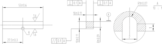
Figure 3. U-shaped, notched standard sample for impact toughness tests.
Download figure:
Standard image High-resolution imageThe martensite multilayer structure, inclusion particles and fracture morphology were analyzed by OM, SEM, EBSD and TEM. The particle size and particle spacing were measured from SEM EBSD and TEM images by the Image Tool software. At least 200 inclusion particles were characterized to ensure the reliability of the results.
3. Results
3.1. Martensite packets and blocks at different quenching temperatures
Figure 4 shows the martensite multilayer microstructure of 20CrMnTi steel quenched at different austenitization temperatures. Figure 4(a) shows that the primary austenite grain in the A-1 specimen is the smallest, approximately 16 μm. However, in the A-2 specimen quenched at 1050 °C, a small amount of mixed crystal state is observed, which is related to the pinning grain boundary produced by TiC particles in 20CrMnTi steel. Due to the dispersed TiC particles that precipitate during annealing, TiC plays a role in pinning grain boundaries during austenitization and hindering grain growth. According to formula (4) [24], the total solid solution temperature of TiC in 20CrMnTi steel is approximately 1189 °C, but due to the decrease in the Ti concentration during solidification, the actual total solid solution temperature is lower. When the temperature reaches 1200 °C, TiC is almost completely dissolved. The grain growth hindrance decreases, and the grain size is large and uniform.

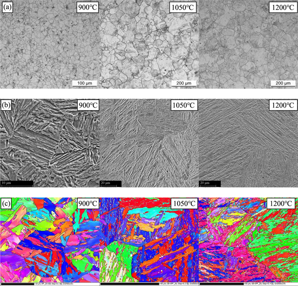
Figure 4. Multilevel microstructure of 20CrMnTi steel quenched at different temperatures.
Download figure:
Standard image High-resolution imageAs the initial austenite grain becomes coarser, the martensite bundle shape gradually changes from a square resembling an equiaxed crystal to a relatively regular rectangle. Meanwhile, the martensite bundle size increases from 6.3 μm to 30.2 μm, as shown in figure 4(b). As the martensite block increases with the beam, the parallelism and aspect ratio of the block gradually increase. As shown in figure 4(c), the block size increases from 1.6 μm to 2.5 or 3.2 μm.
3.2. TiN inclusions in the 20CrMnTi steel
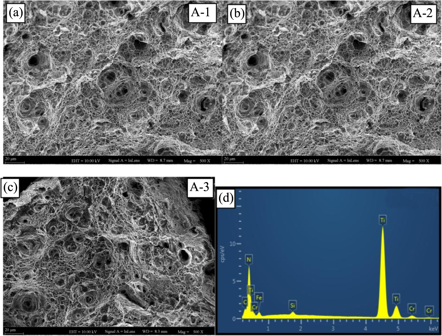
Figure 5 shows the microscopic morphology of the central part of the tensile test specimens. The three groups of specimens are characterized by equiaxed dimples, and the fracture mode is plastic fracture. The larger dimples contain large inclusion particles, and the EDS analysis indicated these particles are TiN particles, as shown in figure 5(d).
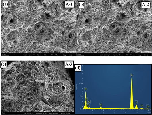
Figure 5. Microscopic morphology and energy spectrum of the tensile fracture site in 20CrMnTi steel.
Download figure:
Standard image High-resolution imageReports in the literature [25–27] have shown that TiN forms above the solidification line of steel, and TiN cannot be dissolved during austenitization. Therefore, the size and distribution of TiN inclusions in the steels were consistent.
Figure 6 indicates TiN inclusion patterns and compositions in 20CrMnTi steel. It could be observed that some of the inclusions have triangular or irregular shapes (figures 6(a) and (b)), but most of these TiN inclusions are square particles (6c and 6d). The main components of the inclusions are Ti and N, and a small amount of C is incorporated into TiN to form Ti(C, N), a composite compound. In the process of TiN formation, nonmetallic inclusions in molten steel, such as MnS, Al2O3, and MgO, are high-temperature stable phases that provide nonuniform nucleation sites for TiN formation. The size of such TiN inclusions is slightly larger than that of the ordinary inclusions [10, 13, 14], which are shown in figure 6(d).
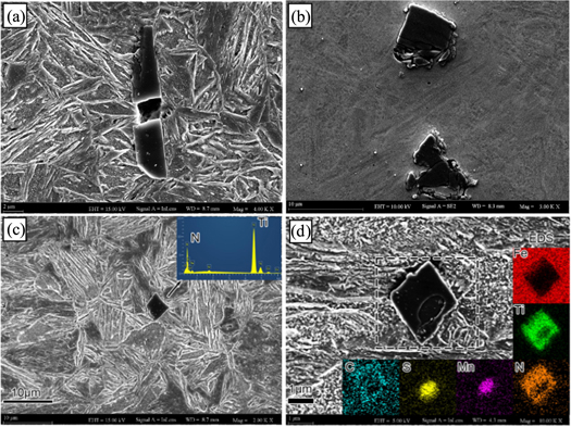
Figure 6. Inclusion patterns and compositions in 20CrMnTi steel.
Download figure:
Standard image High-resolution imageFigure 7 shows that the average size of nearly 200 inclusion particles is approximately 3.5 μm. Most of the particles are in the size range of 1 to 5 μm, and the spacing between particles is mostly in the range of 30 to 120 μm with an average spacing of 83.1 μm. Comparing the three groups of 20CrMnTi steel shows that the austenite grain sizes in groups A-3 and A-2 are larger than the TiN particle spacing, but the grain sizes of the other groups are smaller than the spacing range, as shown in table 3.

Figure 7. Inclusion particle sizes and distributions in 20CrMnTi steel.
Download figure:
Standard image High-resolution imageTable 3. 20CrMnTi steel initial austenite grain, packet, block, retained austenite and inclusion sizes.
| Microstructure type | dr/μm | dp/μm | db/μm | TiN size/μm | TiN spacing/μm | Ar/% |
|---|---|---|---|---|---|---|
| A-1 | 16 | 6.2 | 1.6 | 3.5 ± 2.1 | 83.1 ± 48.2 | 1.5 |
| A-2 | 70 | 23.0 | 2.5 | 1.4 | ||
| A-3 | 91 | 30.2 | 2.9 | 1.6 |
3.3. Mechanical properties
3.3.1. Tensile properties at room temperature
Figure 8 exhibits the effect of different quenching temperatures on the strength and plasticity of 20CrMnTi steel. With increasing quenching temperature, the yield strength and tensile strength of the 20CrMnTi steel decrease, but the area shrinkage and elongation remain nearly constant, as shown in figure 8.

Figure 8. Changes in the tensile properties of 20CrMnTi steel quenched at different temperatures.
Download figure:
Standard image High-resolution imageFigure 9 shows the macroscopic fracture morphologies of tensile specimens. The fiber zone and radiation zone are not clear; however, the shear lip is clearly distinguishable on all of the fracture surfaces. Figure 9(a) displays that the fiber zone and radiation zone are relatively rough and are accompanied by a large number of small holes, which are large dimples that form during the stretching process due to the presence of inclusions, as shown in figure 5(a). A large number of secondary cracks are visible in the fractures of the A-2 and A-3 specimens, and these cracks may be caused by the inconsistency between the hard inclusion particles and large multilayered structure.
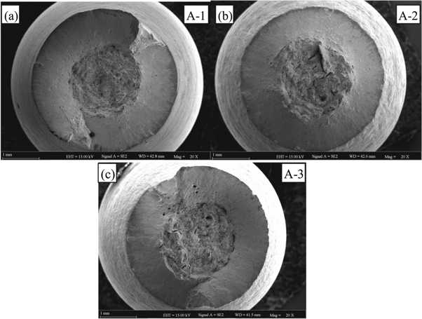
Figure 9. Macroscopic morphologies of tensile fractures in 20CrMnTi steel.
Download figure:
Standard image High-resolution image3.3.2. Fracture toughness
The loading P-displacement curves of the samples from the fracture toughness test are shown in figure 10. As the initial austenite grain size increases, the force P required to cause unstable crack propagation in the sample decreases, and the loading displacement v increases, which indirectly indicates that the fracture toughness of the 20CrMnTi steel samples decreases as the initial austenite grain size increases. In addition, the loading-displacement curve in figure 10(a) is still smooth after reaching the PQ value, while the shifted curves in figures 10(b) and (c) show large changes after reaching the PQ value. Brittle fracture occurs during the fracture process, and the crack growth rate is fast.

Figure 10. 20CrMnTi steel fracture toughness displacement load curve.
Download figure:
Standard image High-resolution imageThe crack length a was measured on the fracture surface, and KQ was calculated according to formulas (1) and (2), shown in table 4. However, the evaluation criteria of the measured KQ value are greatly affected by the yield strength and cannot be verified by formula (3). Therefore, the fracture toughness was determined by KQ.
Table 4. 20CrMnTi steel fracture toughness KIC value.
| Microstructure type | a (mm) | f (a/w) | PQ (kN) | KQ (MPa·m1/2) |
|---|---|---|---|---|
| A-1 | 16.38 | 0.585 | 17.4 | 105.9 |
| 16.41 | 0.586 | 17.7 | 108.6 | |
| A-2 | 16.45 | 0.587 | 12.7 | 78.5 |
| 16.46 | 0.587 | 12.8 | 79.3 | |
| A-3 | 16.4 | 0.576 | 12.4 | 76.2 |
| 16.35 | 0.586 | 12.7 | 77.6 |
As shown in figure 11, as the initial austenite grains coarsen, the fracture toughness of the 20CrMnTi steel decreases. This behavior is different from that of 20CrNi2Mo steel. As the quenching temperature increases, the initial austenite grains increase and the fracture toughness of 20CrNi2Mo steel increases [22].

Figure 11. Relationship between austenite grain size and the fracture toughness of 20CrMnTi steel.
Download figure:
Standard image High-resolution image3.3.3. Impact toughness
The impact toughness results for 20CrMnTi steel are shown in figure 12. As the initial austenite grains coarsen, the impact toughness seriously decreases, and the fracture toughness has a similar trend. This behavior is different from that of 20CrNi2Mo steel. As the quenching temperature increases, the initial austenite grains increase and the impact toughness of 20CrNi2Mo steel increases [22].
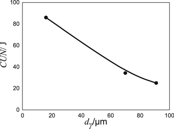
Figure 12. Relationship between the impact toughness and initial austenite grain size of 20CrMnTi steel.
Download figure:
Standard image High-resolution image4. Discussion
4.1. Fracture mechanism analysis
- (1)Fracture toughness
The small-grain-size sample quenched at 900 °C experiences ductile fracture dominated by a dimple morphology in the steady-state crack extension zone above the passivation zone, while the large-grain-size samples A-2 and A-3 have a brittle cleavage fracture mode above the passivation zone. Figure 13 shows the microscopic topographies of the steady-state extension zone of the fracture crack for the three fracture-toughness specimens. Figure 13(a)shows that, sample A-1, which has a small grain size, is mainly characterized by ductile fracture, and the fracture is composed of a large number of equiaxed dimples and partial quasi-cleavage morphology. The quasi-cleavage plus cleavage plane is the main fracture feature in the A-2 and A-3 specimens with a large grain size. Here, the smooth curve characteristics after the PQ value in figure 10(a) are confirmed, and the characteristics of the large deflections in the curves in figures 10(b) and (c) are also confirmed. Therefore, these results confirm that the fracture mode of the A-1 sample in the fine-grain state is ductile fracture, and the fracture mode of the A-2 and A-3 specimens in the coarse-grain state is brittle fracture.
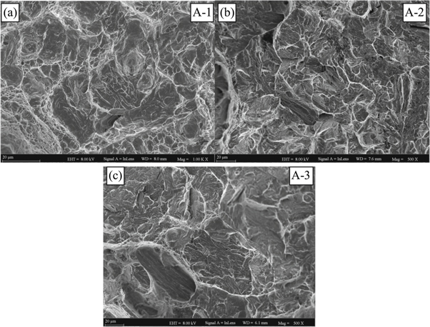
Figure 13. Morphologies of 20CrMnTi steel fracture crack growth.
Download figure:
Standard image High-resolution imageFurther fracture analyses were conducted to reveal the cause of brittle fracture in 20CrMnTi low-carbon martensitic steel. The results indicated that TiN particles may be the cause of brittle fracture in steel with a coarsen crystalline state. Figure 14 shows the TiN particles found in the fracture site of the 20CrMnTi steel fracture-toughness sample. As indicated by the black arrow, the TiN particles in the figure are broken and are not complete square TiN particles, as shown in figure 6. Under a high tensile stress, these hard and brittle inclusion particles are easily broken by microcracks. According to Smith's theory, the cracks generated by the breakage of such inclusion particles spread to nearby substrates under the influence of external stress, resulting in cleavage fracture of the matrix. However, the Smith model is for establishing grain boundary cracking and is based on ferrite. Whether this model can be applied to lath martensite requires further discussion. In addition, a few cleavage platforms are present in the fine-grain A-1 sample, as indicated by the red wire frame in figure 14(a), while the region between the outer red wire frame and the blue wire frame is considered to be quasi-cleavage. The blue wire frame highlights a typical dimple. However, this type is not found in the fracture site of the coarse state.
- (1)Impact-toughness
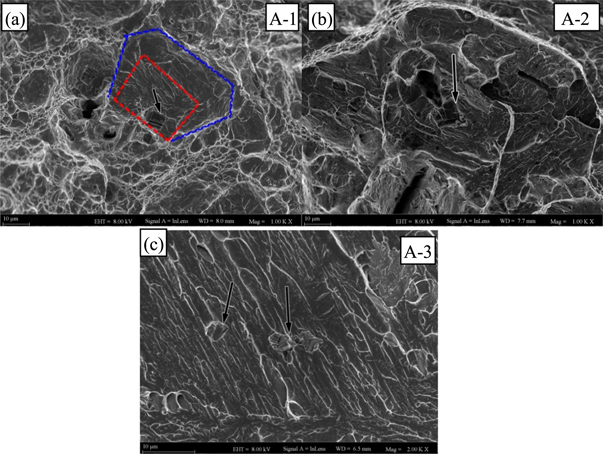
Figure 14. Fracture ductility and fracture mechanism of 20CrMnTi steel with different initial austenite grain sizes.
Download figure:
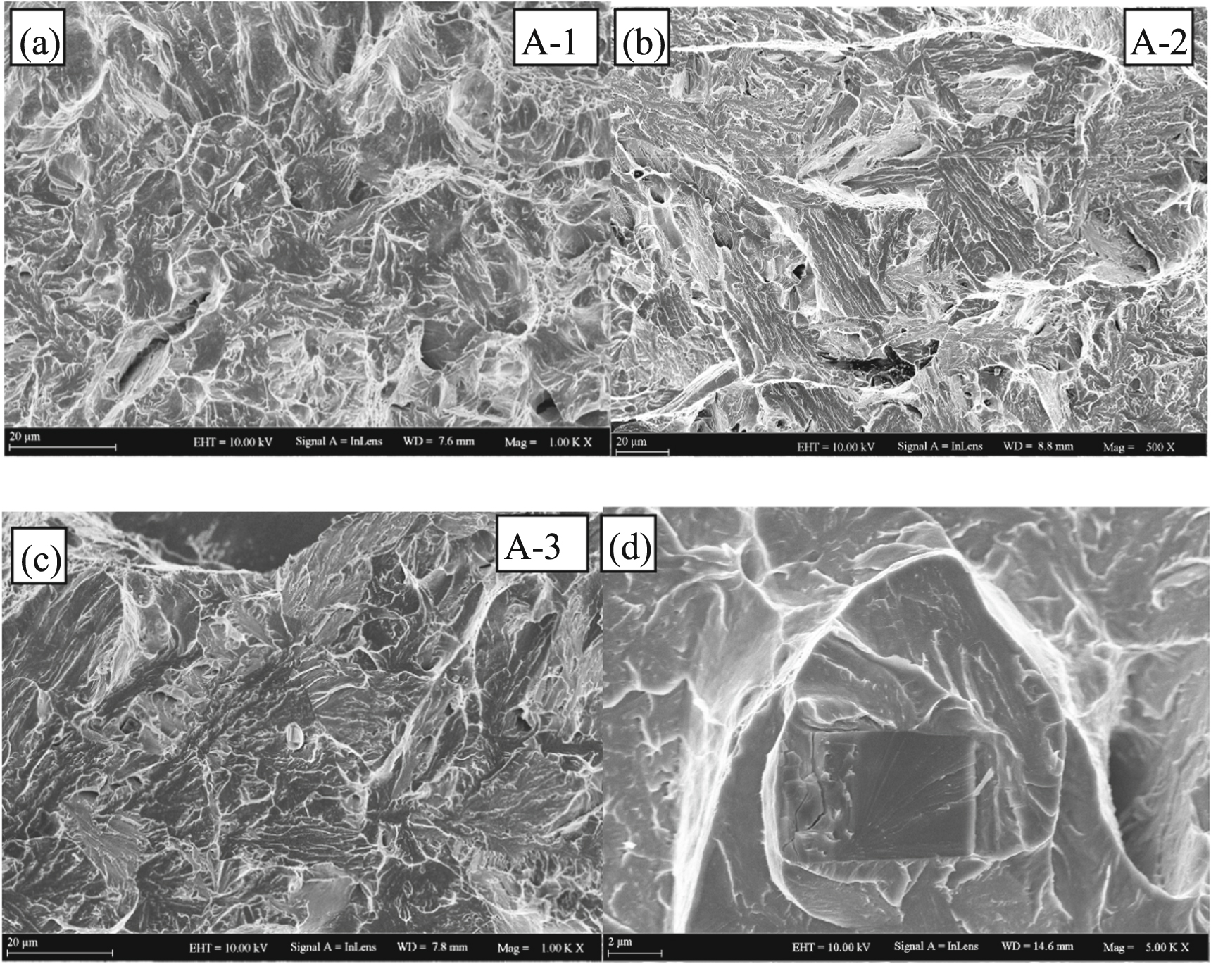
Standard image High-resolution imageFigure 15 shows the microscopic topographies of the crack-propagation zones of the 20CrMnTi steel impact-toughness fracture samples. Figure 15(a) shows that group A-1 is mainly characterized by cleavage fracture with a small number of dimples, which is different from the fracture mode of the fracture-toughness sample and indicates a brittle fracture mode. The fracture mode of the impact specimens in groups A-2 and A-3 is still brittle fracture dominated by cleavage fracture, which is consistent with the fracture mode of the fracture-toughness specimens, as shown in figures 15(b) and (c). A large number of broken TiN inclusion particles can also be observed on the fracture surface, as shown in figure 15(d). Therefore, in the impact-toughness test, the TiN inclusion particles lead to the occurrence of cleavage fracture.

Figure 15. 20CrMnTi steel impact toughness and crack propagation morphology.
Download figure:
Standard image High-resolution image4.2. The TiN inclusion controlled brittle fracture
Gupta [28] and others used ANSYS finite element analysis software to analyze the inclusion particles in the matrix of steel. The results show that the force direction results in a horizontal tensile stress in the simulated sample. When the inclusion particles are rigid, a high concentration of stress occurs at the tip of the sharp corner perpendicular to the square particle. The force in the horizontal direction is also large, while the force of the particles is very small. When the inclusion particles are plastic particles, the matrix is subjected to low stress, and the particles are subjected to a high compressive stress.
In the 20CrMnTi steel fracture-toughness and impact-toughness tests with the three-point bending specimen and impact specimen, the crack tip is subjected to tensile stress perpendicular to the crack-propagation direction, and both specimens satisfy the load model in the [28], indicating that the matrix near the inclusions is under stress and likely to experience cleavage fracture.
Hou et al [29] used MSC Marc finite element analysis software to calculate the stress field around an inclusion and then simulated the stress and strain fields of TiN inclusions and the surrounding matrix under tensile loading. The shape and direction of loading have a crucial influence on the stress concentration around the substrate. At the same time, the spacing between two inclusions has a significant effect on the strength and size of the stress field, which causes the crack initiation region to not be located at the inclusion particles and grain boundaries. The study shows that there is a critical value for the spacing between two inclusions. When the spacing exceeds this critical value, the maximum stress in the matrix is located between two inclusions, making it easy for microcracks to sprout, as shown in figure 16.
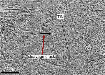
Figure 16. Cracks due to high-stress concentration.
Download figure:
Standard image High-resolution imageIn this experiment, the microstructure of the section at 1/2 of the fracture-toughness test in the coarse-grain sample shows that the main crack mainly propagates in the form of flat fracture cracks, and these cracks pass through the martensite. The bundle structure also has a small amount of plastic deformation, indicating that fracture mainly occurs via cleavage, as shown in figure 17(a). In addition, there are a large number of secondary cracks and inclusions in the vicinity of the main crack, and some of the inclusions are traversed by a secondary crack, as shown in figure 17(b). These cracks show that TiN inclusions have an important influence on cleavage cracking in 20CrMnTi martensitic steel.
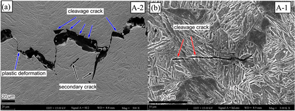
Figure 17. Crack cleavage in fracture toughness test of 20CrMnTi steel.
Download figure:
Standard image High-resolution image4.3. The influence of inclusions on fracture considering martensite packets
Table 5 shows the multilevel structure, inclusion and toughness data for 20CrMnTi steel. Table 5 indicates that as the martensite multilayer structure coarsens, the fracture toughness and impact toughness of the experimental steel decrease, especially the impact toughness, which decreases to 71%. The reason is that the brittle fracture caused by the inclusion of TiN causes a severe decrease in the toughness.
Table 5. Multilayered structure, inclusion and toughness of 20CrMnTi steel.
| Microstructure type | dr/μm | dp/μm | db/μm | TiN size/μm | TiN spacing/μm | KQ/MPa·m1/2 | CUN/J |
|---|---|---|---|---|---|---|---|
| A-1 | 16 | 6.2 | 1.6 | 3.5 ± 2.1 | 83.1 ± 4 | 107.2 | 86 |
| A-2 | 70 | 23.0 | 2.5 | 78.9 | 34.3 | ||
| A-3 | 91 | 30.2 | 2.9 | 76.9 | 25 |
Statistical analysis of the cleavage plane of the fracture toughness and impact toughness fracture revealed that the cleavage plane sizes of the A-1, A-2 and A-3 groups are 7 μm, 24.5 μm and 29.3 μm, respectively. The average cleavage plane of martensitic steel is close to the average of the martensite bundle, suggesting that the martensite bundle size may be a microscopic factor controlling cleavage fracture. This result is similar to the results obtained by Deng Canming, Wang Chunfang and others [30, 31].
Figure 18 is a crack-propagation EBSD diagram and a strain contour diagram of a group of steel fracture toughness specimens. Figure 18(a) shows a small-grain-size sample from the A-1 group, and a large stress field is generated at the position where plastic deformation occurs, as shown in figure 18(b). Other locations where no stress is generated crack by cleavage. Figures 18(c) and (d) show that most of the crack propagation in the horizontal direction occurs via cleavage, and the generated high-stress region is small, indicating that the matrix is not deformed in many regions. This lack of deformation also explains why the toughness of the fine-grain test steel is superior to that of the coarse-grain steel. The crack perpendicular to the propagation direction of the main crack plastically deforms, but the stress and strain are small. The crack corresponds to the low energy avulse dimple structure in the fracture morphology, as indicated by the arrow in figure 18(e). The flat and straight crack is the cleavage plane.

Figure 18. 20CrMnTi steel fracture-toughness specimen crack-growth EBSD and strain contour diagram.
Download figure:
Standard image High-resolution imageCareful observation reveals that the cleavage crack is not a neat linear segment and contains a convex portion, indicating that during the cleavage crack-propagation process, the martensite bundle or grain does not completely control the microstructure. Thus, it is necessary to further observe the fracture. We found that unlike the cleavage fracture morphology of ferritic steel, an obvious river-like pattern and cleavage step are not present. Instead, a tear ridge similar to a quasi-cleavage fracture appears, as shown in figure 19(b). A statistical analysis indicated that these lines are arranged in parallel and consistent with the direction of the martensite bundle, and their width is close to the size of the martensite block, indicating the lines may be a fracture of the martensite block structure, a deflection at the interface and interface or plastic deformation. Thus, the martensite block also contributes to the toughness.

Figure 19. 20CrMnTi steel fracture toughness cleavage surface morphology.
Download figure:
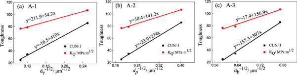
Standard image High-resolution imageThe relationship between the multilevel structure of cleavage fracture martensite and toughness can be established by plotting the Hall-Petch relationship, as shown in figure 20. The austenite grains, martensite bundles and martensite blocks in the martensite hierarchical microstructures of 20CrMnTi steel positively correlate with the toughness, and the slopes are similar, indicating that each unit has a great influence on toughness. Therefore, the martensite bundle structure cannot be used as the only unit for effective control, but the structure can be combined with only the fracture, which shows that the martensite bundle is the main microstructure influencing toughness.
Figure 20. Relationship between the toughness parameters of 20CrMnTi steel and the multihierarchy organization of martensite.
Download figure:
Standard image High-resolution image
As shown in table 5, the average pitch of TiN inclusion particles is 83.1 μm, and the microstructures of the fine and coarse crystals are shown in the following figure. In the average space between two TiN particles, there may be 4 to 5 small crystalline grains or two TiN particles present directly in the adjacent two large grains. The external conditions in our test are fixed, i.e., all the specimens have the same force state during the test, and the stress field distribution is consistent. According to above mentioned, the microcrack initiation position may be the tip of the inclusion or between two adjacent inclusions. There are a large number of initial austenite grain boundaries and martensite bundle boundaries between two inclusions for the small grain size. For crack initiation at the tip of the inclusion, when the stress concentration reaches a certain value, a large number of high-angle grain boundaries appear in the high-stress field, but the cracks begin at the sharp corners of the inclusions and extend to the nearby matrix. Dislocations and cracks have great resistance that is coupled with the coordinated deformation of the nearby low-stress zone structure and makes it difficult for cracks to continue to appear through cleavage. This result proves that the fracture-toughness specimens in group A-1 experience ductile fracture. A small amount of cleavage or quasi-cleavage surface is found only in the inclusions. Due to the absence of large area cleavage, no cleavage or quasi-cleavage fracture occurs during the ductile fracture process of the fine-grained samples. This behavior is attributable to the interface of the fine crystals at large angles easily accommodating deformation and reducing the stress concentration in the high-stress region.
For fine-grain samples, the fracture surface is usually dimple-quasi-cleavage fracture, while for coarse-grain samples, the surface is usually quasi-cleavage-cleavage fracture. In the model of the A-3 coarse-grain sample, we found only a small amount of high-angle grain boundaries between two adjacent inclusions. Therefore, two kinds of cleavage crack initiation may occur for the A-3 sample. In one initiation mechanism, a high-stress concentration is located at the sharp corner of the inclusion, and the cleavage crack occurs and extends to the grain boundary or beam boundary to form the cleavage surface. Due to the difference in height between the two cracks, shear stress occurs at the grain boundary or beam boundary, resulting in plastic deformation under the action of this shear stress, i.e., the dimple tearing the side in figure 18. Another crack initiation method is to initiate cracks at high-angle grain boundaries between adjacent inclusions under a high-stress concentration. Therefore, the sample in the fine-grain state has a better toughness during the fracture controlled by TiN inclusions.
5. Conclusion
- (1)As the quenching temperature increases, the size of the initial austenite grains, martensite packets and blocks increases; TiN inclusions are high-temperature stable phases that do not dissolve in the matrix and are mostly square shaped and dispersed.
- (2)There are two types of cleavage crack initiation: a. cleavage cracks occur at the sharp corners of inclusions with large stress concentration, and propagate to grain or martensite packets boundaries to form a cleavage surface; b. cracks initiate at large-angle interfaces between adjacent inclusions under the high stress concentration.
- (3)TiN inclusions are the main cause of cleavage cracking in 20CrMnTi steel. Under high stress concentrations, TiN inclusion particles can cause two cleavage crack initiation mechanisms, leading to a cleavage fracture of the sample.
Acknowledgments
The research documented in this work was financially supported by the National Natural Science Foundation of China(Grant No. 51461006) and the National Natural Science Foundation of China (Grant No. 51671060) and the Natural Science Foundation of Guizhou province, China (Grant No. [2014] 2003) and the Major Science and Technology Project of Guizhou Province, China (Grant No.[2014] 6012).