
Abstract
The extensive applications of honeycomb (HC) core in sandwich structures necessitates the influence of the cellular geometry and cell wall base material on the mechanical response to be quantified. In this respect, this paper establishes the mechanics of the deformation and the failure processes of the HC core under the out-of-plane compressive, tensile, and shear loading. The corresponding mechanical properties are determined and the mechanisms of failure of the HC core structure are identified. The influence of the relative density (ρ*/ρs) and the cell aspect ratio (H/c) of the hexagonal HC core on the compressive deformation response, the out-of-plane properties and the characteristic dissipation energy density (DED) of the structure is established. Results show that the compressive strength increases exponentially from 1.5 to 10.6 MPa over the relative density range of 0.028 ≤ (ρ*/ρs) ≤ 0.125. The out-of-plane shear modulus, G13 and G23 are 33.9 and 58.2 MPa, while the shear strength, τ13 and τ23 are 1.07 and 2.03 MPa, respectively. The HC core with a low aspect ratio (H/c < 2.64) failed due to the early debonding of the double-wall hexagonal cells, while at H/c ≥ 2.64, by elastic buckling of the cells. A phenomenological model is formulated to highlight the combined effects of both parameters on the compressive strength (σc) of the HC cores, covering the range of 0.028 ≤ (ρ*/ρs) ≤ 0.056 and 2.5 ≤ (H/c) ≤ 5.62. Furthermore, the characteristic dissipation energy density (DED) under the out-of-plane compression varies linearly within the range of 2.5 < (H/c) < 5.62 for the HC core with ρ*/ρs = 0.056. The HC core with H/c = 3.96, but with twice higher ρ*/ρs exhibits about twice larger DED. These resulting properties and failure mechanisms of the anisotropic paper-based HC core are useful for the validation of the predictive computational models.
Export citation and abstract BibTeX RIS

Original content from this work may be used under the terms of the Creative Commons Attribution 4.0 licence. Any further distribution of this work must maintain attribution to the author(s) and the title of the work, journal citation and DOI.
Nomenclature
| ρ* | density of the HC core |
| σc | axial compressive strength of HC core |
| ρs | density of the bulk material |

|
cross-sectional area of HC core sample |
| c | hexagonal cell size |
| E3 | Young's Modulus under compression loading |
| ET | Young's Modulus under tensile loading |
| G13 | shear modulus in transverse direction |
| G23 | shear modulus in ribbon direction |
| H | core height |
| l | cell wall length |
| t | cell wall thickness |
| θ | core angle |
| σT | axial tensile strength of HC core |
| τ23 | shear strength in ribbon direction |
| τ13 | shear strength in transverse direction |

|
deformation under compression loading |

|
compressive strain |
1. Introduction
A typical honeycomb (HC) sandwich structure consists of a hexagonal honeycomb core layer, sandwiched between two thin plates forming the face sheets of the structure. The HC core structure could be fabricated from metallic foils such as aluminum, polymers including Kevlar and Aramid, and resin-impregnated papers. The stiff face sheets are often made of the same alloy, fiberglass, or carbon fiber-reinforced polymer (CFRP) composite laminates in the case of the paper HC core. Compared to the conventional structures, these sandwich structures offer lightweight construction, increased flexural rigidity, out-of-plane strength and stiffness, and improved stability. The structure is designed such that the face sheets carry the flexural load while the HC core carries the normal and shear loads in the planes with the normal outward axis to the cellular core. While the mechanics of the FRP composite laminates for the face sheet have rigorously been studied [1], limited information is available on the deformation and failure of the HC cores, particularly those fabricated from the resin-impregnated papers [2–5]. Under the lateral forces, the compressive failure mode of the HC structure in the through-thickness direction, and the associated localized buckling of the HC core are of primary concern [6–8].
The properties and behavior of the HC core are dictated by the density and anisotropy of the cell wall material. However, some significant properties of the HC core are strongly influenced by the honeycomb cell geometry, particularly the shape and size of the cell, and the wall thickness [9, 10]. Consequently, the interaction of these geometrical parameters and the density of the wall material in defining the properties of the HC core should be established. In this respect, the out-of-plane elastic properties and behavior of the HC core are the most critical from the structural performance point of view [6, 9]. The in-plane tensile, compressive and shear strength of the HC core, have been established through experimentation [8, 11, 12] and using analytical models [13]. Many researchers have performed experimental and numerical investigations on the quasi-static compressive behaviors and energy absorption capacity of aluminum HC structures [6, 14–17]. The compressive strengths of square aluminum HCs are independent of the cell aspect ratio and the presence or absence of the face sheets bonding [6]. A parametric study on the elastic behavior of HC structures as a function of the geometric configuration of the cellular cells showed that the effect of the cell wall thickness is more pronounced than the total height of the core, when considering the equivalent rigidities [13]. In the hexagonal aluminum HC core structure with a lesser number of cells, the boundary effect had a considerable impact on the crush strength, while the core angle showed an effect of less than 10% on the strength value. The mechanical responses in the in-plane loading direction are significantly influenced by the changes in the core geometric parameters than that of the out-of-plane loading [16]. The out-of-plane crushing resistance was reported to be twice in the magnitude of their in-plane strength [18]. In addition, the post-buckling load for the aluminum core sandwich HC is dependent on the core height, core cell wall thickness and geometrical imperfections in the HC core [17]. While the observed behavior is typical of the HC core structures made of homogenous, isotropic materials such as aluminum, it does not represent the response of the resin-impregnated anisotropic paper HC cores.
The deformation response of the HC core structures made of different cell wall materials has been well described [19, 20]. Under the out-of-plane shear loading of the HC core, failure has been observed due to fracture of the cell wall [7, 21]. However, limited works have been reported on the flatwise tensile and the out-of-plane properties of the phenolic resin-impregnated paper HC core, such as Nomex [5, 12]. In addition, the influence of the physical and geometric parameters of the paper-based HC structures are yet to be explored. Extensive experimentation is required to establish the influence of the cellular geometry on the physical and mechanical behavior of the Nomex HC core structure. In this respect, this paper quantifies the mechanics of the deformation and the failure processes of the resin-impregnated fiber-reinforced paper HC core structure under the out-of-plane compressive, tensile and shear loading. The corresponding mechanical properties are determined and the mechanisms of failure of the HC core structure are identified. The influence of the physical parameter (expressed in terms of the relative density) and the geometrical parameter (represented by the cell aspect ratio) of the hexagonal HC cell on the resulting out-of-plane compressive responses of the structure are established. A phenomenological model is formulated to highlight the combined effects of both parameters on the compressive strength of the HC cores. The results could serve as the high-fidelity input data for the equivalent homogeneous hexagonal HC core properties and behavior in the finite element (FE) simulation of the corresponding HC sandwich structures. The observed failure mechanisms are useful for validating the predictive FE model.
2. Materials and experimental procedures
2.1. Honeycomb core materials
The HC core panels employed in this study are supplied by Hexcel Composites. These panels are designated as HRH 10 for representing the specialized resin-impregnated aramid fiber paper type and cellular geometry [22]. The geometry and parameters of the HC core are shown in figure A1 of the appendix. These HC core panels are supplied with the paper density, ρs = 1.14 g cm−3 and cell wall thickness, t = 0.055 mm. It is manufactured by the expansion process [20, 23], followed by the sequence of dipping the HC core structure into the phenolic resin bath for achieving specific densities and stiffness levels. The primary fiber direction in the cell wall is oriented in the ribbon direction (figure A1), normal to the HC cell axis (X3). The panels supplied have three different core densities and two cell sizes, as listed in table 1. The structural density is determined based on a 100 × 100 mm2 specimen of the corresponding panel in accordance with the ASTM C271 standard [24]. The hexagonal HC cell has a wall-length, l = 1.85 mm and the core angle, θ = 30°. The panels with the structural density of 64 kg m−3 are also supplied with three different cell height, H as shown in table 1. The panels were cut into square specimens of 50 × 50 mm2 for the flatwise compression and tensile tests, and rectangular specimens of 150 × 50 mm2 in the ribbon and transverse orientation for the out-of-plane shear tests.
Table 1. Specifications of the HC core specimens.
| Core density, ρ* (kg m−3) [Relative density, ρ*/ρs] | |||
|---|---|---|---|
| 32 [0.028] | 64 [0.056] | 128 [0.112] | |
| Cell Height, H (mm) | Cell Size, c (mm) | ||
| 4.8 | 3.2 | 3.2 | |
| 8 | — | B1 (2.50) | — |
| 12.7 | aA2 (2.64) | B2 (3.96) | C2 (3.96) |
| 18 | — | B3 (5.62) | — |
aThe (bracket) next to the specimen ID denotes the cell aspect ratio (H/c).
2.2. Experimental procedures
The flatwise compression, tension, and out-of-plane shear tests on the HC core specimens are performed on the Instron electromechanical testing machine with a ±50 kN load cell. The tests are performed in a displacement control mode with a machine crosshead speed of 0.5 mm min−1. Each set of the tests is repeated three times to establish the repeatability of the results. The load-displacement response of the HC core specimen throughout each test is recorded. The average measured response is employed when determining the structural stiffness, elastic modulus, out-of-plane compressive, tensile and shear strengths, and the dissipated energy density.
The flatwise compression tests are conducted in accordance with the ASTM C365/C365M standard [25]. The compressive load is applied using an upper self-aligned steel platen to ensure an even distribution of the applied pressure to the HC core specimen.
The flatwise tensile tests conform to the ASTM C297 standard [26]. The Nomex HC core (Specimen B2 in table 1) is sandwiched between the face sheets made of 8-ply unidirectional CFRP composite laminates, each having the of 1 mm. The epoxy adhesive films (Redux 219/2- NA) are used to join the Nomex core with the CFRP face sheets. The HC sandwich specimens are vacuum-bagged and cured in an autoclave with a pressure of 0.02 MPa at 110 °C for 1 h. After 1 h of cooling at room temperature, the specimens are bonded to the steel loading blocks with liquid epoxy (Hysol EA9309.3NA) and cured in an oven at 120 °C for 1 h. The specimens are further kept at room temperature for 2 h. The assembly of the HC sandwich specimen in the tensile grip prior to the flatwise tensile test is shown in figure 1.
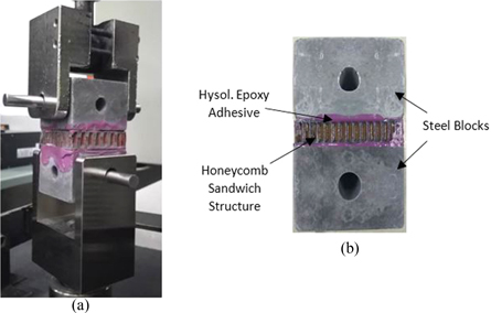
Figure 1. (a) The assembly of the HC sandwich specimen in the flatwise tensile test jig, and (b) the HC sandwich specimen with the loading blocks.
Download figure:
Standard image High-resolution imageThe out-of-plane shear tests of the HC core (specimen B2 in table 1) are performed in accordance with the ASTM C273 standard [27]. The length-to-thickness ratio, L/H of the specimen is 12 to minimize the out-of-plane normal stress-induced throughout the shear test. Each bare HC core sample is bonded to two metallic plates using epoxy adhesive films (Redux 219/2- NA). The sample is cured in an oven at 120 °C for 1 h, and then kept at room temperature for 2 h. The bonded specimen is then assembled in a pin-loaded jig for the test, as shown in figure 2.
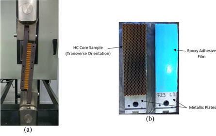
Figure 2. (a) Out-of-plane shear test assembly of the HC core specimen, and (b) the HC core specimen and adhesive film prior to bonding.
Download figure:
Standard image High-resolution image3. Results and discussion
3.1. Deformation and the failure processes
The load-displacement response and the corresponding failure mechanism observed for each test are presented and discussed as follows.
3.1.1. Flatwise compressive behavior
The measured load-displacement curves of the flatwise compression test for the HC core geometry (with the core specimen B2, table 1) are shown in figure 3. Reasonably good repeatability of the compressive response is demonstrated through the three tests. Results show an initial linear elastic behavior until the maximum compressive load level of 10.8 kN is reached. This level defines the average flatwise compressive strength of the HC core structure, as the peak load per unit flatwise area of the HC core specimen, to be 4.01 MPa. The corresponding displacement of 0.5 mm is about 4 to 5% of the displacement at the initiation of the crushing stage. The initial slope of the load-displacement curve at 21.6 kN/mm represents the structural stiffness of the HC core. This is followed by a sudden load drop to 62.8% of the peak value, due to localized buckling of the HC cells. The sudden load drop is attributed to the relatively brittle Nomex HC structures while the more ductile aluminum HC core displays a gradual decrease of the load through a rounded peak of the curve [28]. The crush zone of the HC core structure is defined over a displacement of 8.5 mm with the crushing load (strength) of 4.7 ± 1.2 kN. The observed variation in the crush load is likely due to the weak cells located around the free edges of the HC core specimen, with respect to buckling. Additional compacting displacement causes the densification of the HC core, resulting in a sudden increase in the load, as observed in figure 3.
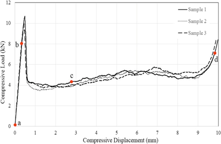
Figure 3. Load-displacement curves of the HC core under flatwise compressive loading (specimen B2).
Download figure:
Standard image High-resolution imageThe deformed shapes and failure features of the HC core at various stages of the compressive loading are illustrated in figures 4 and 5. Each photo in figure 4 corresponds to the stage of the loading, as marked on the load-displacement curves, shown in figure 3. The initial (reference) unloaded HC core specimen is shown in figures 4(a) and 5(a). Figure 4(b) represents the HC core specimen under elastic deformation at 70% of the compressive strength. Fine wrinkles are observed to continuously form along the vertical walls of the cells throughout the elastic response. Localized buckling of few cells along the edges of the HC core specimen occurred with an audible sound, following the attainment of the peak load. With continuous loading (displacement) during the crushing stage, all cells experienced buckling, as shown in figure 4(c) for crushing displacement of 2.8 mm. The crushed cells of the HC core during the densification stage of the loading, marked as point d in figure 3, are shown in figures 4(d) and 5(b). It is worth noting that the buckling planes of the HC core cells are off-centered; closer to the top-loading platen or the lower base plate. Thus, the face sheets, when used, could help in the stiffening of these cells against localized buckling. The collapse of the cells causes severe distortion of the initial hexagonal-shaped cells. In addition, the collapse of the cells along the free edge of the specimen resulted in the severe distortion of the shape of the core specimen, as shown in figure 5(b). If the face sheet is present, a large stress would be induced in the HC core/face sheet interface region.
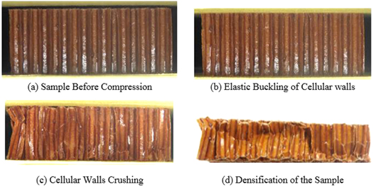
Figure 4. The geometry (side view) of the HC core specimen at the various stages of the flatwise compression test. Refer to figure 4 for the corresponding load and displacement values.
Download figure:
Standard image High-resolution image
Figure 5. (a) The as-received hexagonal HC core (specimen B2), and (b) after the flatwise compression test.
Download figure:
Standard image High-resolution image3.1.2. Flatwise tensile behavior
The load-displacement response of the HC sandwich specimen under the flatwise tension is shown in figure 6. The abscissa records the machine crosshead displacement that represents the combined extension of the HC core, transverse displacement of the CFRP face sheets, and to the much lesser extent, the steel blocks and the load train. Fairly good repeatability of the tensile response is demonstrated with the four tests. The initial linear response with a relatively low slope at 18.2 kN mm−1 represents the elastic straightening of the cellular walls of the HC core structure. A slight increase in the slope of the curve is observed at about 25% of the displacement at fracture, representing the stiffness of the HC core material. The corresponding tensile elastic modulus, ET of the HC core at 137.5 MPa is higher than the compressive counterpart. The load reaches the maximum level at 8.65 ± 0.45 kN, followed by a sudden load drop due to the fracture of the specimen. Since the fracture occurred across the HC cells, the maximum load attained could be used to define the tensile strength, σT of the HC core at 3.47 MPa. In addition, the sudden fracture of the core section of the HC sandwich specimen is reflective of the brittle-like fracture of the phenolic-impregnated Nomex paper [4, 5].
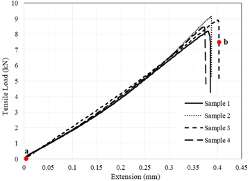
Figure 6. Tensile load-displacement curves of the HC core with CFRP composite laminate face sheets (Specimen B2).
Download figure:
Standard image High-resolution imageFigure 7(a) shows the reference HC sandwich specimen prior to the flatwise tension test (the condition marked a in figure 6(a)). The fractured specimen at the end of the test (point marked b) is shown in figure 7(b). The fractographs show that brittle-like fracture occurred across the cellular structure. This is reflected from the limited deformation of the hexagonal-shaped cells (figure 7(b)), and the sudden fracture event (figure 6). The fracture plane is oriented perpendicular to the loading direction; thus, the fracture event is likely dictated by the maximum principal stress. In addition, the separation of the double-wall cells at the highest tensile load could be observed, as shown by the light white patches areas in figure 7(b).
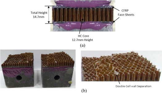
Figure 7. HC sandwich specimen (a) prior to the flatwise tension test, and (b) at the end of the test.
Download figure:
Standard image High-resolution image3.1.3. Out-of-plane shear behavior
The shear load-displacement curves of the HC core specimens for the transverse and ribbon orientations (referring to figure A1) are compared in figure 8. A better repeatability of the load-displacement responses is exhibited for specimens with the ribbon direction. The anisotropic nature of the Nomex HC core is manifested in the superior stiffness and shear load level at fracture for the loading in the ribbon-direction, as shown in figure 8, and reported elsewhere [29, 30]. The average peak load for the ribbon orientation at 15 kN is almost double that for the transverse orientation at 8 kN. The double cell walls in the ribbon orientation that is parallel to the loading direction which, in turn, provides greater flexibility with respect to elastic buckling, thus contributes to the observed higher resistance to shear loading on the specimen. In addition, the fiber orientation of the Nomex paper is also parallel to the ribbon direction which also accounts for the high shear load at fracture, when compared to the transverse orientation. The peak load value divided by the cross-sectional area of the specimen provides the out-of-plane shear strength, τ of the HC core. The measured out-of-plane shear strength in the transverse, τ13 and ribbon, τ23 direction is 1.07 and 2.03 MPa, respectively. The out-of-plane shear modulus is calculated based on the initial tangential slope of the stress-strain curve for the respective specimen. The measured shear modulus in the transverse, G13 and ribbon, G23 direction is 33.92 and 58.26 MPa, respectively.
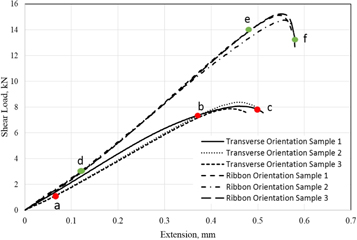
Figure 8. Out-of-plane shear load-displacement curves of the HC core (Specimen B2) with the transverse and ribbon orientation.
Download figure:
Standard image High-resolution imageFigure 9 presents the deformed and failed section of the specimens at various stages of the out-of-plane shear loading, corresponding to the marked points in figure 8. Figures 9(a)–(c) belong to the conditions for the transverse orientation, while figures 9(d)–(f) illustrate the conditions for HC core specimens loaded in the ribbon direction. In the transverse loading direction, the initial linear elastic region is observed up to the load level of 6 kN without any visible failure feature. It is noted that the assembly induces rotations such that the upper region of the specimen also experiences normal separation during the shear loading, while the bottom region is being compressed (figure 9(a)). Above this load level, the cellular walls show shear failure, especially in the upper displaced region of the specimen, as indicated by the trace of the shear planes (figure 9(b)). The final failure consists of the cellular walls fracturing across the specimen and closer to the adhesive layer (figure 9(c)). Similar failure processes are exhibited for the HC core specimen loaded in the out-of-plane shear in the ribbon orientation prior to the attainment of the peak load, as illustrated in figures 9(d) and (e), respectively. However, the final fracture of the specimen in the ribbon direction indicates extensive localized deformation in the central plane of the specimen.
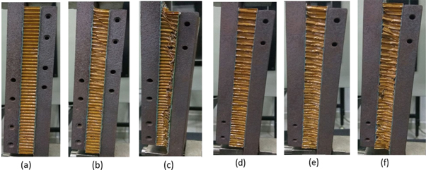
Figure 9. Deformed and fracture features of the HC core (Specimen B2) with transverse orientation (a)–(c) and ribbon orientation (d)–(f) under the out-of-plane shear loading. The corresponding loading stage is as indicated in figure 8.
Download figure:
Standard image High-resolution image3.2. Effects of HC Design Parameters on the Structural Properties and Failure Mechanisms
The effects of the HC core design parameters, namely the cell aspect ratio (H/c) and the relative density (ρ*/ρs) on the mechanical properties and failure mechanisms of the structure are quantified. The properties are extracted from the results of the flatwise compression tests on the HC core specimens. In this paper, the stress is defined by the applied force over the flatwise area of the specimen ( ), while the strain is computed as the deformation per unit height,
  along the height direction of the HC core specimen. The compressive strength, σc of the HC core is defined as the stress corresponding to the buckling load [25]. The mechanics of deformation are described based on the measured load-displacement curve while the failure mechanisms are identified from the fractographic analysis of the fractured specimens.
3.2.1. Effects of relative density of the HC core material
The stress-strain curves of the HC core specimens for the different relative densities (specimen B2 and C2) are compared in figure 10. The cell aspect ratio is fixed at 3.96. Results show that the compressive strength is slightly more than doubled from 4.01 to 8.86 MPa when the relative density is doubled from 0.056 to 0.112, respectively. However, the onset of buckling occurs at a similar axial displacement of the specimens at 0.04 mm. The compressive modulus of the specimen C2 (ρ*/ρs = 0.112) at 225.0 MPa is also higher when compared to the specimen B2 (ρ*/ρs = 0.056) at 120.8 MPa. The high strength and modulus properties are derived from the excess phenolic resin in the higher structural density for the HC core specimen C2. This, in turn, provides the higher and increasing apparent stiffness of the specimen throughout the crushing stage, as reflected in the positive slope of the stress-strain curve for specimen C2. However, the crushing zone is similar, as the height of both specimens examined are identical.

Figure 10. Stress-strain curves of the HC cores with different relative densities. The cell aspect ratio, H/c = 3.96.
Download figure:
Standard image High-resolution imageThe failed HC core specimens with the different relative densities at the end of the flatwise compression tests are compared in figure 11. Similar fracture features of densified ends of the cells with localized crushed zones are displayed. A larger crushed end zone is experienced by the higher relative density HC core (specimen C2) after sustaining a continuously increasing compressive load throughout the test. This results in excessive buckling and fracture of the less-constrained HC cells located near the traction-free sides of the specimen as shown in figure 11(b).
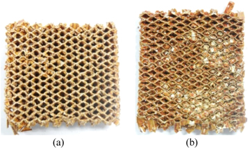
Figure 11. Failure features of the HC core specimens at a different relative density of (a) 0.056 (specimen B2), and (b) 0.112 (specimen C2). The cell height, H = 12.7 mm.
Download figure:
Standard image High-resolution image3.2.2. Effects of cell height of the HC core structure
The stress-strain curves of the HC core specimens with different cell heights, H (denoted by specimens B1, B2 and B3 in table 1) are compared in figure 12. When elastic buckling is the mode of failure, the buckling load is inversely proportional to the height of the cells (similar to the Euler buckling failure). This is demonstrated by the compressive strength of 4.01 and 2.50 MPa for the shorter cell (specimen B2, H = 12.7 mm) and the longer one (specimen B3, H = 18 mm), respectively. The minimum compressive strength for the HC core (specimen B2), as specified by the manufacturer is 2.80 MPa [22]. The elastic modulus, E3 of the specimens are comparable at 127.8 MPa. However, the specimen B1 with the shortest cell (H = 8 mm) does not adhere to the Euler buckling behavior and registers the apparent compressive strength of 2.71 MPa. It is postulated that the cell height for this specimen is less than the critical length for buckling to take place and failure occurred due to the early separation of the double-wall cell of the hexagonal HC core (see figure 13(a)). This has also led to a lower modulus of E3 = 31.56 MPa. Nevertheless, the crushing zone is independent of the cell height of the specimens.
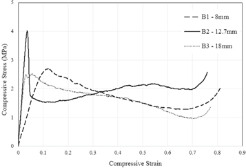
Figure 12. Stress-strain curves of the HC cores with different cell aspect ratio, H/c (c = 3.2 mm, ρ*/ρs = 0.056).
Download figure:
Standard image High-resolution image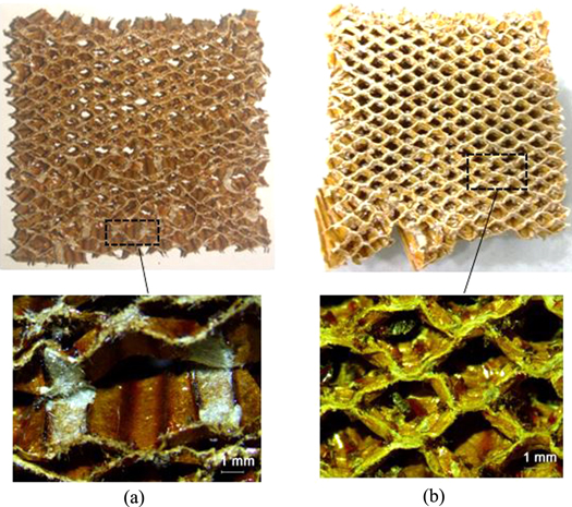
Figure 13. Failure features of the HC core specimens with different cell heights of (a) 8 mm (specimen B1), and (b) 18 mm (specimen B3).
Download figure:
Standard image High-resolution imageThe resulting failure features of the HC core of the three specimens with different cell heights are compared in figure 13 (Fractograph for specimen B2 (H = 12.7 mm) is shown in figure 11(a)). The early crushing failure of specimen B1 has resulted in the separation of the double-wall cells, as highlighted by the light-colored patches in figure 13(a). The buckling failure mode resulted in the distorted traction-free side of the buckled HC cells, as shown in figures 11(a) and 13(b), respectively. In addition, the folding of the hexagonal cell edges under the compressive load is observed. Similar failure mechanisms of the Nomex HC core under compression loading have been reported elsewhere [4, 5, 31].
3.2.3. Effects of the HC hexagonal cell size
Based on the limited geometrical configurations of the available HC core panels, the effects of the cell size on the mechanical responses of the HC core are described in relation to the relative density of the specimens. Figure 14 compares the stress-strain behavior of specimen A2 (c = 4.8 mm, ρ*/ρs = 0.028) and B2 (c = 3.2 mm, ρ*/ρs = 0.056). The previous discussion based on figure 10 showed that the compressive strength of the HC core approximately doubles (4.01:8.86 MPa) with doubling relative density (0.056:0.112). Extrapolating this effect, the specimen A2 with a lower relative density of ρ*/ρs = 0.028 is expected to show a compressive strength of 2.0 MPa. However, the sample exhibits the strength of only 1.08 MPa. Thus, it is postulated that the larger size of the HC cell would result in lower compressive strength of the HC core. Nevertheless, no significant effect of the cell size on the elastic modulus and the crushing zone is observed, as shown in figure 14.
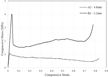
Figure 14. Comparison of the stress-strain curves for different cell size; Specimen A2 (c = 4.8 mm, ρ*/ρs = 0.028) and specimen B2 (c = 3.2 mm, ρ*/ρs = 0.056).
Download figure:
Standard image High-resolution image3.3. Comparative analysis of the mechanical properties of the HC core
The influence of the cell aspect ratio, (H/c) and relative density, (ρ*/ρs) on the modulus and strength properties of the HC core are quantified and discussed in this section. Published test data on similar Nomex HC cores are analyzed along with the measured data from the current study [5, 11, 12, 14, 22, 29, 32–34]. The published data are shown as open symbols while the measured data of the current study are plotted as filled symbols in the remaining figures. The variations of the elastic modulus, E3 with the cell aspect ratio, (H/c) for HC cores with different relative density, (ρ*/ρs) are shown in figure 15. Results show that a comparatively low elastic modulus is exhibited by the HC cores with the cell aspect ratio of less than 2.64. At this low aspect ratio, the failure of the cells is due to the early debonding of the double-wall hexagonal cells (similar to figure 13(a)). At H/c ≥ 2.64, the HC core failure is governed by the elastic buckling of the cells. The observed increase in the elastic modulus of the HC core with increasing cell aspect ratio is particularly pronounced in HC cores with higher relative density. This is because the elastic modulus is dictated by the additional stiffness of the Nomex paper with excess phenolic resin in the HC core with higher relative density. The higher cell aspect ratio would also contain more resin over the larger wall and/or thickness areas of the hexagonal cells.
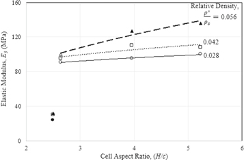
Figure 15. Variations of elastic modulus with the cell aspect ratio and relative density of the HC core.
Download figure:
Standard image High-resolution imageThe combined effects of the relative density, (ρ*/ρs) and the cell aspect ratio, (H/c) on the compressive strength,  of the HC core could be represented by a phenomenological model as:

where the coefficient, A, and exponents, n and ±α are curve-fitting parameters. The compressive strength data relates well with the relative density in the form of a power law, as illustrated in figure 16. The strength data points at any given value of the relative density also represent the variation due to the different cell aspect ratios (as described later, based on figure 17) thus, the apparent scatter of the data should not be indicated by the error bars. It is worth noting that figure 16 does not account for the different mechanisms of failure observed in the HC core. The best-fit line shown is given by:

thus, establishing the exponent, n = 1.8.

Figure 16. The variation of the compressive strengths with the relative density of the Nomex HC cores. The filled symbols represent data from the current study.
Download figure:
Standard image High-resolution image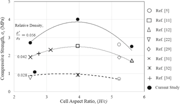
Figure 17. Variations of compressive strengths with cell aspect ratio and relative density of HC core.
Download figure:
Standard image High-resolution imageThe variation of the compressive strengths with the cell aspect ratio, H/c for each value of the relative density examined is shown in figure 17. Results show that the compressive strength increases with increasing cell aspect ratio up to an optimum value at H/c ≅ 3.96. Beyond this ratio, the apparent strength decreases. At the low cell aspect ratio (H/c ≪ 3.96), early failure occurred due to the separation of the double cell walls. On the other hand, at H/c ≫ 3.96, Euler buckling of the slender cells governs the compressive response of the HC core. At H/c ≅ 3.96, the likelihood of the instability failure by buckling balances the compressive crushing of the HC cells resulting in the observed optimum strength. This effect is more pronounced in HC core with high relative density. In HC core with H/c = 3.96, the optimum compressive strength is increased by four times from 0.98 to 3.80 MPa when the relative density doubles from 0.028 to 0.056. In addition, it is noted that the curves are not symmetrical with respect to the vertical line at H/c = 3.96. However, the variations on both sides of the line could be modeled exponentially as:


thus, providing the exponents, α = −2, for H/c ≤ 3.96 and α = 6 for H/c > 3.96. The coefficient, A in the equation (1) is then evaluated for each range of the cell aspect ratio, resulting in A = 1184.0 for H/c ≤ 3.96 and A = 156.5 for H/c > 3.96.
The effects of the relative density and the cell aspect ratio on the compressive strength of the HC core, as proposed in equation (1) could then be modeled as:


The phenomenological model, equations (4a) and (4b) is illustrated graphically in figure 18 with a reasonably good least-squared fitting as reflected by the coefficient of fit, r2 > 0.975. The uncertainty associated with the predicted compressive strength, based on the model is  MPa.
MPa.

Figure 18. Graphical illustration of the effects of relative density and cell aspect ratio on the compressive strength of HC core: (a) H/c > 3.96, r2 = 0.9768 and (b) H/c ≤ 3.96, r2 = 0.9752.
Download figure:
Standard image High-resolution imageThe total energy dissipated by the Nomex HC core specimen under the applied compressive load to failure is represented by the area under the load-displacement curve until the end of the crushing zone (taken up to 70% of the applied strain). The characteristic dissipation energy density (DED) is defined, in this paper, as the total energy dissipated per unit volume of the HC core specimen. The variation of the DED with the cell aspect ratio for the specimen under out of plane compression testing with the relative density of 0.056 is shown by the solid line in figure 19. Results, as shown by the least-squared fitted line of the data with the slope, m = 0.218 (r2 = 0.9964) suggest a linear and significant effect of the H/c ratio on the DED. In addition, the HC core specimen C2 with twice higher relative density of (ρ*/ρs = 0.112) than the specimen B2 at (ρ*/ρs = 0.056), but identical cell aspect ratio (H/c = 3.96), exhibits about twice higher level of the DED. The HC core with higher DED is desirable in view of delaying the catastrophic compressive failure of the structure. The measured dissipation energy density to catastrophic fracture of the HC core (identical to specimen B2) under the tensile loading is 83% lower than the compressive specimen counterpart, as shown in figure 19. A much lower energy density is registered for the specimen in the out-of-plane shear loading (Specimen B2).
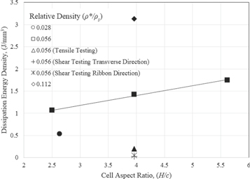
Figure 19. Variation of the dissipation energy density with the cell aspect ratio of the Nomex HC cores for the relative density of 0.056. Other data are included for comparative discussion.
Download figure:
Standard image High-resolution image4. Conclusions
The mechanics of the deformation and the failure processes of the HC core structure under the out-of-plane compressive, tensile and shear loading have been quantified. The structural characterization and the failure mechanism observed during the experimental testing of different cellular HC cores elaborated on the trend of the mechanical properties. This provides the control of the mechanical behavior of the HC core based on the cellular parameters that can be tailored to gain respective mechanical response under out-of-plane loading conditions. The mechanical properties and the characteristic dissipation energy density (DED) of the HC core structure are determined from the measured load-displacement responses. The effects of the cell aspect ratio (H/c) and relative density (ρ*/ρs) on the resulting mechanical properties and the failure mechanisms have been established.
Results show that:
- 1.The compressive strength, σc increases exponentially from 1.5 to 10.6 MPa when the relative density varies within the range of 0.028 ≤ (ρ*/ρs) ≤ 0.125. The high strength and modulus properties are derived from the excess phenolic resin in the HC core with higher relative density.
- 2.The out-of-plane shear modulus, G13 and G23 are 33.9 and 58.2 MPa, while the shear strength, τ13and τ23are 1.07 and 2.03 MPa, respectively.
- 3.The HC core with a low aspect ratio (H/c < 2.64) failed due to the early debonding of the double-wall hexagonal cells, while at H/c ≥ 2.64, the HC core failure is governed by elastic buckling of the cells.
- 4.The combined effects of relative density and cell aspect ratio on the compressive strength of the HC core could be represented by a phenomenological model, covering the range of 0.028 ≤ (ρ*/ρs) ≤ 0.056 and 2.5 ≤ (H/c) ≤ 5.62. The associated uncertainty of the predicted strength is
 MPa.
MPa. - 5.The characteristic dissipation energy density (DED) under the out-of-plane compression varies linearly within the range of 2.5 < H/c < 5.62 for the HC core with ρ*/ρs = 0.056. The HC core with H/c = 3.96, but with twice higher ρ*/ρs exhibits about twice larger DED.

Acknowledgments
The mechanical tests of the HC core specimens were performed at the Composite Technology Research Malaysia (CTRM), Melaka, Malaysia under the supervision of M.A.M. Sah.
Funding
This work is funded by the Aerospace Malaysia Innovation Centre (AMIC) and the Universiti Teknologi Malaysia (UTM) under Project No. AMIC/AM/P02-01 (UTM Grant No. 4C089 and 01M01, respectively). The financial support for Muhammad Salman Khan through Scholarship No. FDP—2014/15 by the National University of Sciences and Technology (NUST), Islamabad, Pakistan, is greatly acknowledged.
Conflicts of interest
The authors declare no conflict of interest. The funders had no role in the collection, analyses, or interpretation of data; in the writing of the manuscript, or in the decision to publish the results.
Appendix

Figure A1. (a) Hexagonal HC cell configuration, and (b) hexagonal HC core structure made of Nomex paper.
Download figure:
Standard image High-resolution image