
Abstract
In this research, the effect of thermal shock has been investigated on the microstructure and cyclic oxidation of Pt-Al-7%YSZ coating applied on Rene-80 superalloy. The microstructural evaluation and phase identification were performed by field emission scanning electron microscope (FE-SEM) and X-ray diffraction (XRD). The thermal shock test consisted of repeated cycles of rapid cooling between 900 °C and 400 °C. Prior to the thermal shock test, the specimen coated by Pt-electroplating, high-activity low-temperature (HALT) aluminizing and the thermal spray of YSZ ceramic layer. From surface towards the substrate; the coating consisted of 5 layers including: 7% YSZ, PtAl2 + β-(Ni,Pt)Al, β-(Ni,Pt)Al with fine precipitates rich in α-(Cr) and α-(W), precipitate-free β-NiAl, and inter-diffusion zone next to the specimen surface. After the thermal shock test, spallation and delamination have been observed in the YSZ layer. The Pt-Al layer was found in upper and lower parts of the coating with different Pt concentration. Also, the chemical composition of the Pt-Al layer demonstrated the removal of PtAl2 particles and β transformation to both γ and γ' phases. Degradation of Pt-Al layer occurred by ratcheting the thermally grown oxide (TGO), rumpling, and cavitation. Comparison of weight changes showed that the thermal shock resistance is improved by Pt-Al-7% YSZ coating.
Export citation and abstract BibTeX RIS

Original content from this work may be used under the terms of the Creative Commons Attribution 4.0 licence. Any further distribution of this work must maintain attribution to the author(s) and the title of the work, journal citation and DOI.
1. Introduction
Nickel-based superalloys have been widely used in the manufacturing of the gas turbine blades due to their excellent mechanical strength at high temperatures [1]. Thermal barrier coatings (TBCs) are usually used to increase the blades life in gas turbines [2]. Thermal barrier coatings usually consist of three layers. The first layer is a metallic bond coat made of MCrAlY overlay coating or diffusional aluminide coating modified with elements such as platinum.The second layer is known as thermally grown oxide (α-Al2O3). The third layer, namely topcoat, is a ceramic material mostly zirconia stabilized with 6–8 weight percent of yttria [3–6]. The ceramic topcoats may be coated with either thermal spray (TS) or electron beam physical vapor deposition (EB-PVD). EB-PVD coats have usually better thermal shock resistance than TS coats due to their columnar microstructure. However, in comparison with EB-PVDs, TS coatings are inexpensive and exhibit lower thermal conductivity coefficient [7].
In-service, temperature changes make the thermal shock as a serious problem in the rotating parts of gas turbine. Also, stability of gas turbine components under thermal shock condition is a great interest for designers [8]. Studying the degradation mechanisms and microstructural changes in TBCs have been a primary concern of researchers. The bond coat oxidation plays a decisive role in both of its degradation and structural changes mechanism. Busso et al [9] and Wu et al [10] have studied the degradation of the high-activity low-temperature (HALT) Pt-Al/EB-PVD YSZ coating interface under cyclic oxidation condition. They pointed out that the degradation occurred by the formation of delamination cracks within the YSZ or the TGO/YSZ interface, rumpled Pt-Al layer and the phase transformation of β to γ΄of the Pt-Al layer. These mechanisms often occur due to the stresses induced by the growth of the (thermally grown oxide) TGO layer and the difference in thermal expansion coefficients of the coating and substrate. Rumpling of the Pt-Al layer leads to the spallation of the coated system [11]. Xu et al [7] investigated the degradation of the CVD Pt-Al/EB-PVD YSZ coating system under thermal shock condition. Based on their observations, the degradation accompanied by spallation in the TGO layer or the TGO/YSZ interface, ratcheting of the Pt-Al layer, rumpling of the Pt-Al layer and β toγ΄phase transformation.
Few researches have been conducted to study the effect of thermal shock on the coating of TS YSZ and HALT Pt-Al bond coat layer. In the present study, the microstructures of HALT Pt-Al/TS YSZ on Rene-80 substrate were evaluated before and after thermal shock.
2. Materials and methods
2.1. Substrate
Cast Rene-80 superalloy, with chemical composition given in table 1, used as the substrate in this study. Rectangular samples with dimensions of 10 × 10 × 2 mm were prepared by wire-cut. The samples were sand-blasted with SiC and alumina powders with 60 and 220 mesh in order to obtain surface roughness of 5 μm. The roughness was measured with TR200 roughness tester. The samples were cleaned and degreased in an ultrasonic bath of acetone and ethanol solution at 1:1 volume ratio for 10 min.
Table 1. The chemical composition of cast Rene-80 superalloy.
| Element | Ni | Cr | Co | Mo | Ti | Al | W | C | Zr | B | Fe |
|---|---|---|---|---|---|---|---|---|---|---|---|
| Content (wt%) | Bal. | 13.88 | 8.81 | 3.98 | 4.91 | 2.78 | 3.51 | 0.17 | 0.08 | 0.01 | 0.09 |
2.2. Coating
A nickel layer was electrodeposited on samples surfaces in a sulfate bath. The platinum layer was electroplated in one liter solution contains 16 ml of type P salt di-nitro di-amino platinum (Pt(NH3)2(NO2)2), 80 g sodium carbonate (Na2CO3), 55 g sodium acetate (NaCH3COO) at 90 °C under a current density of 0.3 A dm−2 and pH of 10.2. The annealing heat treatment at 1050 °C for 2 h was performed on the platinum layer under the vacuum of the 10−5 torr [12]. Then, the samples were cooled in the furnace to 400 °C followed by air-cooling to room temperature. The high-activity low-temperature (HALT) aluminizing process was performed via pack cementation at 750 °C for 3 h, followed by a heat treatment at 1070 °C for 1 hour under argon atmosphere [13]. The YSZ layer applied on samples by thermal spray method with variables specified in table 2. The chemical composition of YSZ powder was given in table 3.
Table 2. The thermal spray parameters.
| Current (A) | Voltage (V) | Flow rate of primary gas (psi) | Flow rate of carrier gas (psi) | Feedstock giving rate (g/min) | Spray distance (mm) | Spray angle (Deg) | Flame outlet temperature (°C) |
|---|---|---|---|---|---|---|---|
| 600 | 2 | 25 | 15 | 100 | 150 | 75–80 | 1300-1400 |
Table 3. The chemical composition of YSZ powder (wt%).
| ZrO2 | Y2O3 | SiO2 | TiO2 | Al2O3 | Fe2O3 | Other oxides |
|---|---|---|---|---|---|---|
| Bal. | 7.0-8.0 | 0.3 | 0.2 | 0.2 | 0.2 | 0.1 |
2.3. Thermal shock test
The thermal shock cycle is shown schematically in figure 1 and was applied on bare (T30) and coated samples (TC30) up to 50 cycles in air. The samples were kept in 900 °C for 30 min, cooled to 400 °C by jet-fan and finally cooled to room temperature in 5 to 7 min. The weight change after thermal shock cycles was measured by an electronic balance with an accuracy of 10−4 g.

Figure 1. Thermal shock test cycle applied on samples in this study.
Download figure:
Standard image High-resolution image2.4. Microstructural evaluation
To reveal the microstructures, electropolishing and electroetching was carried out in 10 ml HCl + 90 ml Methanol and 170 ml HPO3 + 10 ml H2SO4 + 16 g Cr2O3 solutions, respectively after conventional metallographic procedure. Microstructural studies were conducted using a MIRA3-Tescan field-emission scanning electron microscope (FE-SEM) equipped with an energy dispersive spectroscopy (EDS). XRD analysis was performed using Analytica/ILAC diffractometer with a monochromatic radiation of Cu Kα (λ = 1.54060 A). The voltage and current were 40 KV and 30 mA, respectively.
3. Results and discussion
3.1. Microstructure of diffused Pt layer
The cross section microstructure of the electroplated nickel and platinum coating on rough surface of the substrate is shown in figure 2. The thicknesses of nickel and platinum layers were 3 and 5 μm respectively. Nickel layer was applied in order to decrease the adverse effect of the Cr upward diffusion from substrate [14]. The cross section microstructure of the applied coatings after the diffusional annealing heat treatment is shown in figure 3. The total thickness of diffusional layer is 8 to 18.5 μm. Two distinct light (A) and dark (B) areas along with the substrate (C) were recognized. EDS analysis of light and dark areas is presented in table 4. The Pt and Al content of light area were higher than that of the dark area. The Al content of the light and dark areas were lower than that of substrate. Also, the amount of Cr and Co in the dark area were higher than that of the light area, while the Ti content of the light area is higher than that of the dark area.
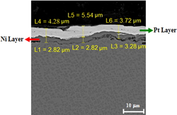
Figure 2. FE-SEM micrograph of polished cross section of electroplated Ni and Pt layers applied on Rene-80 substrate.
Download figure:
Standard image High-resolution image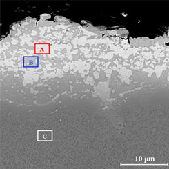
Figure 3. FE-SEM micrograph of polished cross section of Pt layer after diffusional annealing.
Download figure:
Standard image High-resolution imageTable 4. The EDS analysis light (A), dark (B) and substrate (C) areas in figure 3 (at%).
| Zone | Al | Ti | Cr | Co | Ni | Pt | Mo+W |
|---|---|---|---|---|---|---|---|
| A | 14.5 | 7.5 | 3.1 | 2.4 | 49.6 | 20.9 | 1.7 |
| B | 3.4 | 1.6 | 18.6 | 8.4 | 52.9 | 12.4 | 2.7 |
| C | 5.8 | 5.8 | 15.2 | 8.2 | 58.7 | — | 5.9 |
The X-ray elemental maps of the main elements of the coating after the diffusional annealing are shown in figure 4. It can be seen that the Pt and Al were accumulated in the light areas, while Cr, Ni and Co were accumulated in dark areas. The XRD pattern of the coating surface after diffusional annealing revealed the formation of the γ and γ΄ in the coating (figure 5). The results demonstrate that the light and dark areas were γ and γ΄(rich in Pt) phases respectively. During the diffusional annealing, Pt diffuses inward and some alloying elements such as Al diffuse upward into the coating from the substrate simultaneously. Pt dissolved in the γ-γ΄ structure and replaced Ni atoms. Kiruthika et al [15] attributed this behavior to the decrease in defect formation energy and the reduction in the migration energy of the atoms in the intermetallic γ phase. In the presence of Pt, the γ and γ΄peaks shift slightly to the lower angles [16].
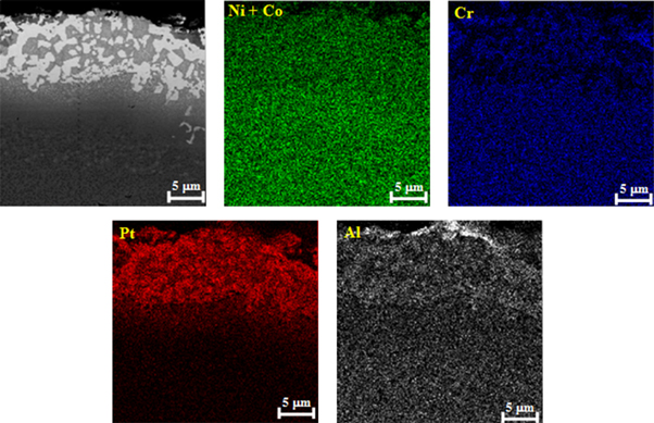
Figure 4. X-ray elemental maps of Pt coating after diffusional annealing.
Download figure:
Standard image High-resolution image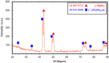
Figure 5. XRD pattern of diffused Pt coating on Rene-80 substrate.
Download figure:
Standard image High-resolution image3.2. Microstructure of Pt-Al layer
The XRD pattern of the coating surface after HALT aluminizing is shown in figure 6. The XRD pattern showed the formation of PtAl2, Ni2Al3, Ni3Al, NiAl and Al2O3 phases in the coating. The formation of Al-Ni intermetallics compounds were due to the Al diffusion downward into the substrate. In the presence of Pt, the effective inter-diffusion coefficient of Al in NiAl phase increases [17]. The diffusion rate of Al in PtAl2 phase is high, and PtAl2 is not a barrier for Al diffusion into the substrate [18].
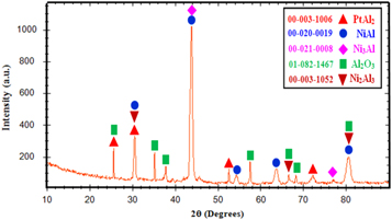
Figure 6. XRD pattern of Pt-Al coating after the HALT aluminizing.
Download figure:
Standard image High-resolution imageThe cross section microstructure of the Pt-Al layer after HALT aluminizing on Rene-80 superalloy, is shown in figure 7. The EDS analysis of the different specified zones in figures 7(a) and (b) are presented in table 5. The total thickness of coating was 60–65 μm and four distinct layers were identified. The outer layer consisted of a two phases structure of β-(Ni,Pt)Al and PtAl2. This is due to the inward diffusion of Al and outward diffusion of nickel during the HALT aluminizing [6].
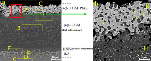
Figure 7. (a) The cross-section FE-SEM micrograph of HALT Pt-Al coating on superalloy Rene-80 (b) magnified region in Fig. a.
Download figure:
Standard image High-resolution imageTable 5. The chemical composition of the specified zones in figure 7 obtained by EDS analysis (at%).
| Zone | Al | Ti | Cr | Co | Ni | Mo | W | Pt |
|---|---|---|---|---|---|---|---|---|
| A | 51.0 | — | 5.7 | — | 21.7 | 2.0 | 1.0 | 16.7 |
| B | 44.3 | 1.1 | 4.7 | 4.2 | 35.8 | 4.5 | 2.8 | 1.2 |
| C | 30.3 | 1.2 | 5.3 | 6.4 | 47.3 | 2.0 | 1.4 | 4.8 |
| D | 10.6 | 7.7 | 13.6 | 7.5 | 49.8 | 5.9 | 3.4 | — |
| E | 18.2 | 3.7 | 23.1 | 8.7 | 33.1 | 9.2 | 3.0 | — |
| F | 36.6 | 2.6 | 4.3 | 5.3 | 47.6 | 2.2 | 0.2 | — |
| G | 7.3 | 4.8 | 14.4 | 8.8 | 55.4 | 5.2 | 3.0 | — |
| H | 32.6 | 1.1 | 8.9 | 1.5 | 14.2 | 9.7 | 30.9 | — |
| I | 53.9 | 1.4 | 7.8 | 1.7 | 15.6 | — | 0.7 | 17.9 |
| J | 50.0 | 0.4 | 2.1 | 4.4 | 37.6 | 0.8 | 0.4 | 3.0 |
| K | 52.1 | 1.5 | 7.1 | 1.9 | 14.8 | — | 0.6 | 20.7 |
The middle layer was β-(Ni,Pt)Al along with precipitates. The Pt content in upper zone of this layer is higher than that of lower zone. The main reason for the decrease in platinum concentration in the middle layer is the high concentration of Al in the HALT process, which prevents significant penetration of Pt. The activity of Al increases with increasing its concentration. On the other hand, the reduction in Pt and Ni concentration leads to reduction in their activity and diffusion coefficient [15]. Therefore, according to the chemical composition of the lower zone of the middle layer, it is suggested that this area consists of δ-Ni2Al3 phase. The precipitates in the middle layer were mostly α-W with a size of less than 1 μm. Platinum often prevents the upward diffusion of the substrate refractory elements into the outer layer of the coating. Therefore, α-W precipitates are formed in the middle layer of Pt-Al coatings [19, 20]. Chromium penetrates the coating to a lesser extent than nickel and its diffusion coefficient is low because the atomic size of Cr is larger than that of Al [15]. Therefore, the average Cr concentration throughout the middle layer is low.
The inner layer consists of β-NiAl phase without precipitates, which is common in aluminide coatings and forms with a low thickness at the top of the inter-diffusion zone (IDZ) [21].
The IDZ contained columnar needle shape precipitates of α-Cr phase. The formation of IDZ is due to the upward diffusion of Ni from the substrate into the coating. Therefore the concentration of refractory elements such as Cr increases and they precipitate as the columnar needle shape phases [19].
3.3. Microstructure of TBC
Large equiaxed pores usually formed in the vicinity of unmelted zirconia particles were observed in the surface microstructure of the Pt-Al-7%YSZ coating (figure 8). The formation of pores results in tensile stress at the surface of the coating. Therefore, the stress required to propagate the horizontal cracks in the Pt-Al/YSZ interface is reduced during the thermal shock conditions. Intersplat pores reduce the thermal conductivity and strain tolerance of the YSZ layer [22].

Figure 8. FE-SEM surface micrographs of (a) Pt-Al-YSZ coating and (b,c) magnified region in Fig. a.
Download figure:
Standard image High-resolution imageIntersplat cracks are usually formed parallel to the interface of splats due to the thermal shrinkage and stresses created during the cooling of splats [23].
The semi-spherical particles of light color seen in some areas in figure 8, often consisted of YSZ particles. These particles solidified before reaching the substrate since they lost their thermal energy as a result of high spraying distance.
The cross section microstructure of the YSZ layer deposited by thermal spray on the surface of Pt-Al layer is shown in figure 9. The thickness of YSZ layer was 105–125 μm. The coating had a lamellar structure and consisted of separate splats with cracks and voids. The orientations of the splats were parallel to the spray direction and had a long columnar structure. The intersplat cracks were often parallel to the coating plane and perpendicular to the spray direction. The TGO layer rich in Al2O3 with small amounts of NiO and Cr2O3 with a thickness of about 3 to 3.5 μm was formed during the thermal spray process on the surface of the Pt-Al layer. Formation of this layer was also observed by Shirvani et al in thermal spray of YSZ [24].
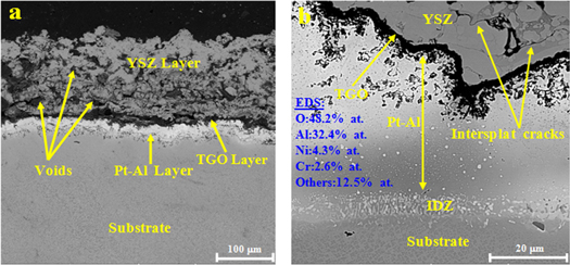
Figure 9. FE-SEM cross-section micrographs of (a) Pt-Al-YSZ coating and (b) YSZ/TGO/Pt-Al interfaces after thermal spray.
Download figure:
Standard image High-resolution image3.4. Thermal shock behavior of uncoated and coated Pt-Al-7% YSZ samples
The weight changes of the uncoated (T30) and coated (TC30) samples during thermal shock tests are shown in figure 10. The weight gain of T30 and TC30 samples up to 3 cycles was approximately the same and about 0.2 mg cm−2. This can be related to the constant oxygen diffusion rate in the oxide scales of the samples. As the oxidation continues, Ni, Al and Cr react with oxygen on the surface of the substrate and form oxide scales [25]. However, the weight gain of T30 was increasing continuously with the number thermal cycles in such a way that the maximum weight gain of 0.71 mg cm−2 was measured after the 50th cycle. In comparison, the weight change of TC30 could be divided into three distinct zones. In zone I, continuous oxygen uptake and formation of the oxide layer was occurred until 19th cycle. In zone II, from 19th to 43th cycles, the substrate protection was carried out by oxide scale formation with the least weight changes (0.03 mg cm−2). In zone III, from 43th to 50th cycles, a continuous weight losses was observed due to the spallation of both the coating layers and oxide scale. The total weight change of TC30 after 43 cycles was much less than that of T30 being only 0.32 mg cm−2. It seems that the presence of Pt in the coating has decreased the growth of the oxide scales on the surface of the aluminide coating [26].
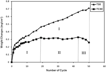
Figure 10. Weight change versus number of cycles for thermal shock of T30 and TC30 samples.
Download figure:
Standard image High-resolution imageThe cross section microstructure of the TC30 sample after 50 cycles is shown in figure 11. As can be seen, the YSZ layer was spalled significantly. The average thickness of the YSZ layer decreased to less than of 60 μm. Some of the micro-cracks in TGO/YSZ interface have propagated into the YSZ layer. Also cavities were formed in the YSZ layer by linking the cracks to each other. During the thermal shock cycles, the cavities have led to the delamination of the TGO/YSZ interface. The YSZ layer was subjected to compressive stresses and viscoplastic deformation due to the high-temperature gradient across the coating. Therefore the displacement of the YSZ layer has resulted in the buckling of the coating and its delamination [22]. The weight loss of the TC30 sample was due to the spallation of the oxide scale and the YSZ layer simultaneously.
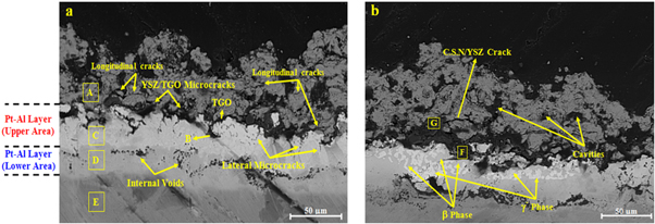
Figure 11. FE-SEM cross-section micrographs of (a) TC30 sample (b) β to γ phase transformation in Pt-Al layer after 50 cycles of thermal shock.
Download figure:
Standard image High-resolution imageThe average thickness of the Pt-Al layer decreased to 50 μm. The Pt-Al layer was divided into two distinct lighter (upper) and darker (lower) areas. The EDS analysis of the specified zones in figure 11 are presented in table 6. The chemical composition of the Pt-Al layer in some regions was revealed the formation of β-(Ni,Pt)Al phase (figure 11(a)). It seems that PtAl2 particles spalled along with the oxide scale. Similar results have been reported by Zafir Alam et al during the cyclic oxidation of Pt-Al coatings [27]. The decrease in Al concentration in the Pt-Al layer has resulted in β to γ' phase transformation in some regions (figure 11(b)). The chemical composition of the Pt-Al layer in these areas revealed the formation of γ'-(Ni,Pt)3Al and β-(Ni,Pt)Al phases. The β to γ' phase transformation was due to the inter-diffusion of Al within the TGO layer and the substrate as well as the upward diffusion of Ni from the substrate to the Pt-Al layer. The lower areas of the Pt-Al layer were contained the γ-Ni(Pt) phase. The amount of Al in these areas was less than 15% atomic. The amount of other substrate elements increased by comparison to the upper area of Pt-Al layer except for Pt and Al. These results are consistent with the observations of Taylor et al [28].
Table 6. The chemical composition of the specified zones in figures 11(a) and (b) (at%).
| Zone | O | Al | Ti | Cr | Co | Ni | Y | Zr | Mo | W | Pt |
|---|---|---|---|---|---|---|---|---|---|---|---|
| A | 68.8 | 0.3 | — | — | 0.1 | 0.1 | 2.2 | 26.8 | 0.3 | 0.9 | — |
| B | 55.5 | 26.5 | — | 1.4 | 2.7 | 12.2 | — | — | 0.1 | 0.3 | — |
| C | — | 28.7 | 1.8 | 6.8 | 4.2 | 38.3 | — | — | 0.1 | — | 18.8 |
| D | — | 7.6 | 2.9 | 9.0 | 6.6 | 57.2 | — | — | 5.2 | 1.0 | 10.5 |
| E | — | 6.8 | 4.2 | 15.1 | 8.8 | 56.6 | — | — | 5.0 | 2.7 | — |
| F | 52.0 | 38.3 | 1.3 | 3.9 | 0.7 | 1.6 | — | — | 0.8 | 0.4 | 1.0 |
| G | 35.5 | 14.9 | 0.1 | 17.6 | 0.2 | 31.1 | — | — | 0.2 | 0.1 | 0.3 |
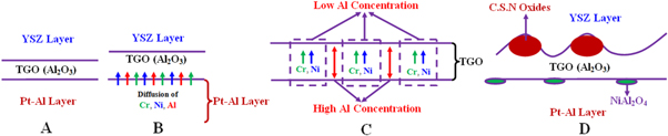
The thickness of the TGO layer was slightly decreased to 2 to 3 μm. The upward diffusion of Al into the TGO layer was restricted due to the formation of γ' phase in the upper area of the Pt-Al layer. The self-diffusion coefficient of Al in γ' phase is lower than β and γ phases [17]. In some areas, the thickness of the TGO layer increased locally. In these areas, the aluminum concentration was low and nickel segregation was observed due to the compositional inhomogeneity during the TS process. Therefore, nickel diffusion from the TGO layer led to the formation of detrimental mixed oxides. The detrimental mixed oxides usually consist of chromia, spinel and nickel oxide (CSN). In these areas, the aluminum content was insufficient to form an alumina layer. These results are consistent with the observations of Chen et al [29]. Furthermore, the growth stresses of the TGO layer have resulted in surface cracks. Therefore, the TGO layer has lost its continuity in some areas facilitating the penetration of NiO and Cr2O3. The growth of Ni(Cr,Al)2O4 and NiO resulted in a stress build up at their interfaces, leading to crack nucleation and growth into the YSZ layer as CSN/YSZ crack [29]. The schematic illustration of CSN oxides formation at TGO/YSZ interface during thermal shock is shown in figure 12.
Figure 12. The schematic illustration of CSN oxides formation at TGO/YSZ interface during thermal shock in air: (A) Formation of primary TGO due to pre-oxidation during TS process, (B) Diffusion of Ni, Cr and Al into primary TGO, (C) Ni and Cr segregation in the TGO layer, (D) Formation of CSN oxides at high Ni and Cr concentration regions.
Download figure:
Standard image High-resolution image
In some regions of the TGO/Pt-Al interface, the formation of TGO in the Pt-Al layer (ratcheting) and lateral micro-cracks were observed. These micro-cracks provide short paths for diffusion of oxygen into the Pt-Al layer and lead to cracking and delamination of the coating [30]. The formation of lateral micro-cracks was mainly due to NiAl2O4 spinel formation at the TGO/Pt-Al layer [31], the hypo-stoichiometric composition of Pt-Al layer [28] and γ'phase formation in the upper area of the Pt-Al layer [9, 32].
Micro voids were observed at the interface of the upper and lower areas of the Pt-Al layer. The formation of these voids is due to the inter diffusion of Al in the lower area of the Pt-Al layer with its upper area and substrate. Due to the formation of γ phase in the lower area of the Pt-Al layer, the upward diffusion of Al was more favourable [33].
Rabiei and Evans [34] reported the existence of these voids while investigating the mechanisms of degradation caused by the TGO growth on APS-TBC coatings.
Longitudinal cracks were observed in the YSZ layer near the YSZ/TGO interface. The tensile stresses created in thermal cycles are the main source of formation of longitudinal cracks. The longitudinal cracks are formed by linking of the YSZ intersplat micro-cracks and propagated during thermal shock cycles, causing the YSZ delamination [35, 36].
4. Conclusions
In this research, the effect of thermal shock has been investigated on the microstructure and cyclic oxidation of Pt-Al-7%YSZ coating applied on Rene-80 superalloy. Based on the observations:
- Pt-Al layer consisted of γ-(Ni,Pt)Al and γ'-(Ni,Pt)3Al phases, which Pt atoms substitute for Ni atoms in γ΄and γ phases.
- Pt-Al-%7YSZ coating by HALT aluminizing method, includes 5 layers of 7% YSZ, PtAl2 + β-(Ni,Pt)3Al, β-(Ni, Pt)Al, β-NiAl, and inter-diffusion zone (IDZ).
- The cross-section microstructure of the TS YSZ layer showed transverse micro-cracks and dispersed cavities. Moreover, intrasplat cracks, shrinkage pores, partially melted splats have been observed in the surface of the coating.
- The presence of Pt-Al-%7YSZ coating improves thermal shock resistance since the weight changes due to the formation of oxide compounds in the coated samples are reduced compared to the uncoated ones.
- After 50 cycles of thermal shock test, the coating includes 4 zones of porous YSZ layer, continuous TGO layer of Al2O3 with CSN oxides, β-(Ni,Pt)Al + γ΄-(Ni,Pt)3Al, and γ΄-(Ni,Pt)3Al + γ-Ni(Pt).
- Delamination of YSZ layer, removal of PtAl2 particle from the outer part of the Pt-Al layer, rumpling and ratcheting of the Pt-Al layer along with β to γ + γ΄phase transformation are the degradation mechanisms of the Pt-Al-7% YSZ coating.