
Abstract
A series of Ce3+/Tb3+ singly doped and Ce3+, Tb3+ co-doped Ca3GdNa(PO4)3F phosphors were synthesized via high temperature solid-state reaction in a reductive atmosphere. The crystal, luminescence properties, energy transfer mechanism and thermal stability of the samples were investigated in detail. The Ce3+ doped phosphors can be excited in the range from 250 to 330 nm. The Ce3+,Tb3+ co-doped phosphors exhibit characteristic emission of Ce3+ and Tb3+ simultaneously under the excitation of 301 nm. In addition, the energy transfer efficiency from Ce3+ to Tb3+ reaches as high as 78.6% when the doping amount of Tb3+ is 0.20. The mechanism of energy transfer between Ce3+ and Tb3+ ions is demonstrated to be a dipole−dipole interaction. The luminescence characteristics show that this phosphor can be a platform for modeling a new phosphor and application in the solid-state lighting field.
Export citation and abstract BibTeX RIS

Original content from this work may be used under the terms of the Creative Commons Attribution 3.0 licence. Any further distribution of this work must maintain attribution to the author(s) and the title of the work, journal citation and DOI.
1. Introduction
Apatite compounds are regarded as important phosphor matrix materials due to their excellent thermal and chemical stability. Among them, Ca5(PO4)3F is the simplest apatite structure and the first apatite compound proved to have P63/m space group. On the basis of Ca3(PO4)3F, apatite fluorescent materials with very rich compositions were obtained by changing the types of cations, anion groups and channel atoms in the crystal [1]. In apatite compound crystals, there are usually two cationic crystal lattices, which are locally symmetric at C3 point (4f lattices) and locally symmetric at Cs point (6h lattices). These two crystal lattice sites can be replaced by rare earth elements, because the 4f and 6h lattice sites have different requirements on the radius and valence state of substituted ions, which often make apatite phosphors with special spectral characteristics [2].
Green phosphors are useful to obtain white light source with high color rendering in the field of illumination [3]. It is also advantageous to obtain the display effect of high color purity in the display field. In recent years, many green phosphors based on apatite crystals have been reported. For example, the green phosphor Ca6La4(SiO4)2(PO4)4O2:0.01Eu2+ prepared by Xia [4], its emission peak of 500 nm was emitted from the 4f and 6h positions occupied by Eu2+, and the quantum efficiency was 57.73%. Besides, Tian [5] prepared fluorescent powder Ca9Sr(PO4)6Cl2:Ce3+,Tb3+ by high temperature solid phase method. Based on the effective energy transfer between Ce3+ and Tb3+, the green emission peak of Tb3+ at 541nm was significantly increased, and the energy transfer efficiency of Ce3+ → Tb3+ was up to 76%. However, no relevant reports have been reported on the study of green phosphor with apatite structure Ca3GdNa(PO4)3F as matrix. Based on the efficient energy transfer between Ce3+ and Tb3+, it is expected that new green fluorescent materials with apatite structure can be obtained by mixing Ce3+ and Tb3+ in the Ca3GdNa(PO4)3F matrix. As the emission wavelength of semiconductor chips is gradually extended to short-wave UV and deep UV [6], this kind of fluorescent powder has the potential to be used in the solid-state lighting field in the future.
A series of phosphors Ca3GdNa(PO4)3F: xCe3+,yTb3+(0 ≤ x ≤ 0.14, 0 ≤ y ≤ 0.28) were prepared by a high temperature solid-state reaction. Then the energy transfer process and mechanism of Ce3+, Tb3+ co-doped phosphor Ca3Gd0.92-yNa(PO4)3F:0.08Ce3+, yTb3+(0 ≤ y ≤ 0.28) were discussed, and the emission spectrum CIE chromaticity diagram was drawn.
2. Experimental
2.1. Materials and synthesis
Powder samples of Ca3Gd1-x-y Na(PO4)3F:xCe3+,yTb3+ phosphors were prepared by a high temperature solid-state reaction. CaCO3(AR), Na2CO3(AR), (NH4)2HPO4(AR), NH4F(AR) , CeO2(99.99%) and Tb4O7(99.99%) were used as the raw materials and weighed in a proper stoichiometric ratio with a 10% excess of fluorine for the loss at high temperature. The raw materials were fully mixed and ground in an agate mortar, and the mixture was placed into an alumina crucible and was heated at 1200 °C for 1h in a reducing atmosphere with flowing gas.
2.2. Characterization
The phase purity of the phosphor was checked by powder x-ray diffraction (D/Max-rA 9kw, Japan) with Cu Kα radiation (λ = 0.15406nm) from 15°∼80°(2θ). XRD data for the Rietveld refinement were performed using the computer software: general structure analysis system (GSAS). The particle morphology and microstructure of the samples were examined by scanning electron microscopy (SEM) using a JSM-7610F instrument with a voltage of 10kV. The photoluminescence spectra was recorded on a RF-6000 (Shimadzu corporation, Japan) luminescence spectrometer. The excitation light source was xenon arc lamp, and the spectral scanning step was 1nm.
3. Results and discussion
As shown in figure 1(a), the peaks of all samples conform to the standard card of Ca5(PO4)3F, and no additional peaks of other impurities are found in the diffraction patterns. The phenomenon indicates high purity of the samples and the doped ions will not change the matrix crystal phase. Figure 1(b) shows a partial amplification of XRD of the sample. With the increasing of the doping concentration of Ce3+, the diffraction peak shifts to the lower 2θ because the larger radius of Ce3+ is replaced by the smaller radius of Gd3+, when Tb3+ is not mixed. The offset profile of diffraction peak demonstrates that Ce3+ and Tb3+ have been successfully introduced into the matrix material Ca3GdNa(PO4)3F [7].

Figure 1. XRD patterns of Ca3Gd1-x-yNa(PO4)3F:xCe3+,yTb3+ (a) and magnified patterns in the region 31.8°∼32.2°(b).
Download figure:
Standard image High-resolution imageCa1 forms a tetrahedral structure with 9O coordination points [8] in Ca5(PO4)3F crystal (figure 2), which is a locally symmetric 4f lattice position at C3 point. Ca2 coordinates with 6O and 1F to form a decahedral structure, which is a locally symmetric 6h grid position at Cs points. The O and P in the crystal coordinate to form the structure of (PO4)3− tetrahedron, which is connected with the common edges and angles of Ca1and Ca2 coordination polyhedra respectively.
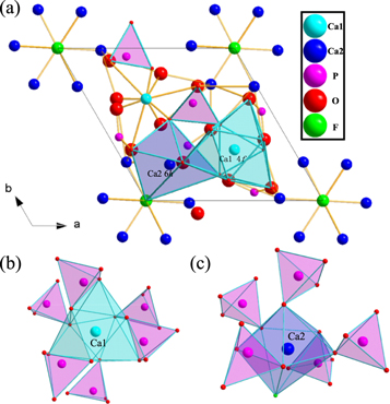
Figure 2. The crystal structure of Ca5(PO4)3 F along the c-axis direction (a) and the coordination environment of Ca1 (b) and Ca2 (c).
Download figure:
Standard image High-resolution imageWe can achieve the radius of each cation in different coordination environments [9] from table 1. Considering the difference of valence state and radius of each cation, the substitution of two Ca2+ by Gd3+ and Na+ had occurred [10]. Matrix crystal Ca3GdNa(PO4)3F was obtained after being replaced by Gd3+ and Na+. In this matrix, Ce3+ and Tb3+ activators were introduced. Ce3+ and Tb3+ replaced Gd3+ in the matrix to form replacement solid solution [11] due to the need to keep valence balance. Figure 3. shows Ca3Gd0.72Na(PO4)3F:0.08Ce3+,0.20Tb3+ samples have irregular micromorphology with relatively smooth surface and particle size ranging from 6 ∼ 14μm.
Table 1. Ionic radii (nm) for given coordination number (CN).
| Ion | Sites | Symmetry | Ionic radius (nm)CN = 7 | Ionic radius (nm) CN = 9 |
|---|---|---|---|---|
| Ca2+ | 4f /6h | C3/Cs | 0.106 | 0.118 |
| Gd3+ | 4f /6h | C3/Cs | 0.100 | 0.1107 |
| Na+ | 4f /6h | C3/Cs | 0.112 | 0.124 |
| Ce3+ | 4f /6h | C3/Cs | 0.107 | 0.1196 |
| Tb3+ | 4f /6h | C3/Cs | 0.098 | 0.1095 |

Figure 3. SEM image of the Ca3Gd0.72Na(PO4)3F:0.08Ce3+,0.20Tb3+.
Download figure:
Standard image High-resolution imageThe emission spectra of the as-prepared samples Ca3Gd1-xNa(PO4)3F:xCe3+(0 ≤ x ≤ 0.14) as shown in figures 4(a), (b). Upon the excitation of 301nm, its emission spectral intensity enhances with the increasing of the doping concentration of Ce3+ [12]. The spectral intensity reaches the highest, when the doping of Ce3+ is 0.08. The doping amount of Ce3+ continues to increase, the concentration quenching phenomenon begins to appear, and the spectral intensity decreases accordingly. Figure 5(a) shows that when the single content of Ce3+ is 0.08, the phosphor has a broadband excitation spectrum from the 4f → 5d transition of Ce3+ at 250 nm–330 nm, and the optimal emission wavelength is 301nm, at which time the broadband emission presents an asymmetric peak [13]. Gaussian fitting was performed on the emission spectrum, and two peaks appeared at 334.47nm and 358.73nm. After Ce3+ is excited, a 5d → 4f transition emission occurs, and 4f splits into 2F5/2 and 2F7/2. Therefore, the emission spectrum comes from Ce3+ occupying the same crystal lattice position. High valence and low ion radius are the most likely to replace likely to replaces the lattice site of 6h crystals with shorter coordination bonds and smaller volume. According to the coordination ion radius in table 1, it can be seen that Ce3+ replaces Gd3+ and occupies the lattice site of 6h [14], and then emits light. Figure 5(b) shows that when the single dosage of Tb3+ is 0.20, the characteristic emission of Tb3+ at 542nm is monitored.

Figure 4. PL spectra of Ca3Gd1-xNa(PO4)3F: xCe3+ monitored at 301 nm (a) and the dependence of PL intensity on doping concentration of Ce3+(b).
Download figure:
Standard image High-resolution image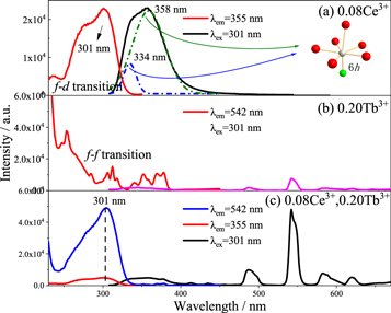
Figure 5. PLE and PL spectra of Ca3Gd0.92Na(PO4)3F:0.08Ce3+ (a), Ca3Gd0.80Na(PO4)3F:0.20Tb3+ (b) and Ca3Gd0.72Na(PO4)3F:0.08Ce3+,0.20Tb3+ (c) phosphors.
Download figure:
Standard image High-resolution imageIn figure 5(c), the emission peak of 542 nm green light was monitored, and the excitation intensity of Ce3+ and Tb3+ co-doped phosphors at 301 nm was much higher than that of single doped Tb3+ phosphors at 301 nm. Then 301 nm ultraviolet light is the best excitation wavelength of Ce3+, and the spectra of figures 5(a) and (b) have a significant overlap, so it can be speculated that there is an energy transfer of Ce3+ → Tb3+ in phosphor Ca3Gd0.72Na(PO4)3F:0.08Ce3+,0.20Tb3+.
As the Tb3+ doping increases, the 355nm broadband emission peak intensity decreases (figure 6(a)). The narrow-band emission peaks in the emission spectrum come from the electron transition of Tb3+ [15], including the spectral peaks of 376 nm, 413 nm, 435 nm and 455 nm radiated by the electron transition of the high-excited energy level 5D3 → 7FJ(J = 6, 5, 4, 3), and the spectral peaks of the low-excited energy level 5D4 → 7FJ(J = 6, 5, 4, 3) radiated by the electron transition of 488nm, 542nm, 582nm and 620nm. Energy transfer efficiency (ηT) can be expressed by [16]:

Among them, IS and IS0 represent the luminescence intensity of sensitizer Ce3+ when doped with Tb3+ and without Tb3+, respectively. The energy transfer efficiency of Ce3+ → Tb3+ can reach 78.6%, when the doping concentration of Tb3+ reaches 0.20.

Figure 6. PL spectra of Ca3Gd0.92-yNa(PO4)3F:0.08Ce3+, yTb3+ phosphors with different Tb3+ contents (a); Dependence of Ce3+ PL intensity and energy transfer efficiency on Tb3+ concentration (b).
Download figure:
Standard image High-resolution imageDexter and Schulman suggest that the distance Rc between Ce3+ ion and Tb3+ can be estimated using the equation [17]:

Where V is the volume of the unit cell volume, xc is the critical concentration, which refers to the total concentration of Ce3+ and Tb3+ when the energy transfer efficiency between Ce3+ and Tb3+ reaches 50% (from figure 6). N is the number of sites that the Ce3+ ions can occupy in the unit cell (N = Z × 2) and of doped ions. In case of Ca3GdNa(PO4)3F:xCe3+, yTb3+ phosphor, V = 0.52371 nm3, N = 2, and xc = 0.18. Upon inserting the value in equation (2), Rc value is determined to be 1.41nm > 0.5nm, therefore the energy transfer mainly occurs through multiple dipole interactions from Ce3+ to Tb3+.
According to Dexter's multi-dipole interaction energy transfer formula and Reisfeld's approximation theory, the energy-transfer mechanism of multi-dipole interaction which can be givens as [18]:

where IS0 and IS have the same meaning as equation (1). Different n values mean different mechanisms of multiple dipole interactions. The dipole-dipole, dipole-quadrupole and quadrupole-quadrupole interactions correspond to curves (IS0/IS) and Cn/3 with n = 6, 8, and 10. The linear relationship reached the optimal one for (IS0/IS) versus C6/3 by comparing the fitting factors of R2 values in figure 7, implying that the energy transfer mechanism from the Ce3+ to Tb3+ ions is a dipole-dipole mechanism in Ca3GdNa(PO4)3F: Ce3+, Tb3+ phosphor.
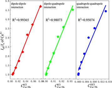
Figure 7. Dependence Iso/Is of Ce3+ on CCe+Tb6/3, CCe+Tb8/3 and CCe+Tb10/3 in Ca3Gd0.92-yNa(PO4)3F:0.08Ce3+, yTb3+ (0 ≤ y ≤ 0.28) phosphors.
Download figure:
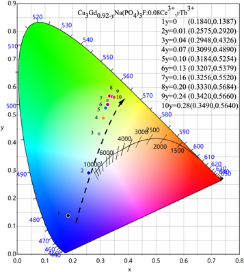
Standard image High-resolution imageThe measured CIE chromaticity coordinates of the Ca3Gd0.92-yNa(PO4)3F:0.08Ce3+, yTb3+(0 ≤ y ≤ 0.28) were presented in the inset of figure 8. Based on energy transfer from Ce3+ to Tb3+, the emitting color can be varied gradually from blue to green region with the increasing doping amount of Tb3+. The purity of green light color continuously increases when the Tb3+ doping amount is 0.2.
Figure 8. The CIE chromaticity diagram of Ca3Gd0.92-yNa(PO4)3F:0.08Ce3+,yTb3+ (0≤y ≤ 0.28) phosphors.
Download figure:
Standard image High-resolution image
The relative brightness stability and color coordinate stability of the phosphors were determined according to GB/T 23595.4-2009 national standard for Ca3Gd0.72Na(PO4)3F: 0.08Ce3+, 0.20Tb3 + prepared under optimal conditions (1200 °C, 1 h). Calculated according to formula (4)–(6):

Where ∆Bhis relative brightness thermal stability(%), B0 and Bh represent the relative brightness(%) of the sample after heat treatment and heat treatment.


Among them, ∆Xh and ∆yhare the stability of color coordinates, X0 and y0 are the unheated color coordinates, and Xh and yh are the heat processed color coordinate. After testing and calculation, ∆Bh value is determined to be 2.56% < 5%, and (∆Xh, ∆yh) = (0.0003, 0.0006), which is also far less than national standard 0.0015. These data indicate that Ca3Gd0.72Na(PO4)3F:0.08Ce3+, 0.20Tb3+ phosphors have good thermal properties and can be used in solid-state lighting.
4. Conclusions
To summarize, Ce3+ and Tb3+ singly doped and co-doped Ca3GdNa(PO4)3F phosphors were successfully prepared and investigated. In Ca3GdNa(PO4)3F: Ce3+, the Ce3+ tent to replace Gd3+ on 6h, and the broad emission band centered at 355nm was observed with optimal Ce3+ concentration being 0.08. We observed the energy transfer in the Ca3Gd0.92-yNa(PO4)3F:0.08Ce3+, yTb3+. With the increasing of Tb3+ doping, the emission spectrum intensity of Ce3+ at 355nm decreased monotonously, while that of Tb3 + at 542nm increased monotonously. When y = 0.20, the energy transfer efficiency of Ce3+ → Tb3+ could reach 78.6%. Meanwhile, the energy transfer was about 1.41nm, and the energy transfer from the Ce3+ to Tb3+ ions was dipole-dipole interaction. The phosphor emitted bright green light and had good thermal stability. All the above results demonstrated that Ca3GdNa(PO4)3F:Ce3+, Tb3+ can be a platform for modeling a new phosphor and application in the solid-state lighting field.
Acknowledgments
The authors would like to acknowledge the financial support in part from the National Key R&D Program of China (Grant Nos. 2017YFB0404300, 2017YFB0404301) and the Natural Science Foundation of Jiangsu Province (Grant No. BK20171128).