

Abstract
The WC particles reinforced Fe-based spray welding layer was fabricated on the surface of 45 steel by plasma arc spray welding technology. The WC particles were irregular polyhedral and spherical, which were fed into the tail of the molten pool. The microstructure, phase composition, microhardness, and dry -sliding wear resistance of the coating were evaluated. The results show that the microstructure of the composite coating exhibits a hypoeutectic structure in addition to the WC, and the spherical WC particles are better preserved than the irregular polyhedral WC particles. The coating added with spherical WC particles has the best wear resistance, which is 1.28 times that of the coating added with irregular polyhedral WC particles.
Export citation and abstract BibTeX RIS
1. Introduction
As a kind of surface strengthening technology, plasma spray welding technology can locally strengthen, pre-protect and repair the surface of many workpiece to extend its service time or re-use it. In recent years, it has been extensive research. Due to particle reinforced metal matrix composite (PRMMCs) combine the properties of metals (high ductility and toughness) with ceramics (high strength and modulus) [1], it has been widely used in mechanical parts requiring high abrasion. The WC particle has good physical properties such as high melting point, high hardness, good stability, and well wetting property, so it is often used as the enhanced phase [2]. Metal-based materials commonly used for cladding are mainly Fe-based alloys [3–5], Ni-based alloys [6, 7] and Co-based alloys [8, 9]. The Fe-based coatings are suitable for repair and reinforcement of most formed workpieces and are inexpensive. Moreover, power-feeding modes of WC particles will also affect properties of the coating. Compared with the synchronous powder feeding, the particles are well preserved and the reinforcing effect is obvious when adopted the back-feeding [10, 11]. Few researchers have focused on the influences of the particulate morphology on the composite coating.
This paper focuses on the effect of two kinds of morphology (irregular polyhedral WC particles and spherical WC particles) on the microstructure and properties of a WC reinforced iron-based coating.
2. Experimental materials
Normalized 45 medium carbon steel was used as the base material. Fe313 alloy powder was used as welding material: Its chemical composition is shown in table 1. The WC particles with different shapes were chosen: Irregular polyhedral WC particles and spherical WC particles in shape with a size of 80–120 mesh. The morphology of the powder is shown in figure 1.
Table 1. Chemical composition of Fe313 alloy powder (wt%).
| Element | |||||
|---|---|---|---|---|---|
| Material | C | Cr | B | Si | Fe |
| Fe313 alloy | 0.1 | 15 | 1 | 1 | Bal. |
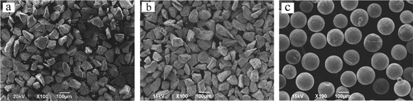
Figure 1. Surface morphology of powder, (a) Fe313 iron-based powder morphology, (b) irregular polyhedron WC particles, (c) spherical WC particles.
Download figure:
Standard image High-resolution imageThe coating was prepared by using a PTA-400D1-ST universal powder plasma spray welder. The main spray welding parameters are as follows: spray welding current is 120 A, Fe-based powder-feeding rate is 12 g min−1, WC particles feeding rate is 6 g min−1, the walking speed of the spray gun is 65 mm min−1, and the swing width is 20 mm.
The microstructure of each sample was observed by optical microscope and scanning electron microscope. The phase composition of the specimens was analyzed by x-ray diffractometer. The micro-area composition and the element distribution were detected by energy-disperse spectroscopy. The hardness of the spay welding layer measured by MH3 microhardness tester. The friction and wear test were carried out on the MMG-10 end face friction and wear testing machine. The sample was made into a disk shape with a diameter of 43 mm and a height of 5 mm. Measuring the weight loss of the sample with an electronic balance.
3. Experimental results
3.1. Microstructure
Figure 2 shows the SEM image of the composite coatings fabricated by adding WC particles with difference shapes. The white parts in the figures are WC particles. It can be seen that the back-feeding technology effectively avoids a large amount of melting of the WC particles. The volume occupied by the spherical WC particles in the coating is larger than that of the irregular polyhedral WC particles, which shows that the irregular polyhedral WC has more melting than the spherical WC. The WC particles are more in the bottom of the coating near the bonding line than the top of the coating. This is because of the WC density is larger than the Fe-based alloy, which causes the WC particles to concentrate in the middle and bottom portions of the layer.

Figure 2. SEM image of the layer, (a) polyhedral WC particle reinforced Fe313 alloy spray welding layer, (b) spherical WC particle reinforced Fe313 alloy spray welding layer.
Download figure:
Standard image High-resolution imageFigure 3 shows the OM micrographs of Fe313 coating without adding WC, adding irregular polyhedral WC and adding spherical WC. The bonding line of Fe313 alloy combined with the 45 steel can be clearly seen from the (a), (b) and (c) diagrams, indicating that the composite coatings and the substrate are in metallurgical bond. From the bonding line to the top of the spray welding layer, the crystalline morphology is from planar crystal to dendrites. This is due to the combined effects of constitutional supercooling and temperature changes in the coating. At the beginning, the molten pool was dissipated through the 45 steel substrate, and its internal temperature is high, which causes the crystallization speed to be slow and crystallizes in a planar manner. Then after removal of the plasma flame, the temperature of the molten pool is rapidly reduced, which causes crystallization speed is faster and crystallizes in a dendritic manner. In addition, it can be seen from the comparison of the three figures (d), (e) and (f), there are coarse columnar dendrites in the Fe-based spray welding layer without WC added, but not found in the counterpart. On the one hand, this may be due to the fact that the WC particles have a chilling effect on the layer, which increase the undercooling of the coating, and increase the nucleation rate; On the other hand, the W and C elements produced by the melting of WC particles diffuse into the iron-based alloy, which generates more eutectic structure, reduces the content of the pre-eutectic dendrites, and inhibits the growth of columnar dendrites.

Figure 3. Microstructure of the coating, (a)(d) iron alloy coating without WC particles addition, (b)(e) add irregular polyhedral WC particles, (c)(f) add spherical WC particles.
Download figure:
Standard image High-resolution imageBefore analyzing the microstructure in detail, it is necessary to know which phases are present in the spray welding layer. Therefore, phase analysis of the coating was carried on by XRD on the polished surface of the sample. XRD results (figure 5) reveals that Fe3W3C, M7C3 (Cr7C3–(Cr, Fe)7C3) and M23C6 (Cr23C6) phases are identified besides the original α-Fe, WC and W2C phases.
Figure 4 shows the SEM image of the WC-reinforced Fe313 alloy spray welding layer. It can be seen that the matrix of the composite coating consisted of a hypoeutectic microstructure, including the eutectic components and the primary dendritic. Additionally, there is a reaction layer around the WC particles.
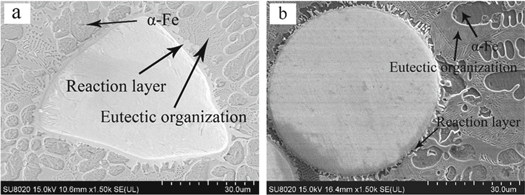
Figure 4. WC particle reinforced Fe-based SEM image (a) irregular polyhedral WC particles (b) spherical WC particles.
Download figure:
Standard image High-resolution imageIn the plasma cladding process, WC particles melted due to the high temperature of the molten pool, which made C and W elements diffuse into the Fe-base. Furthermore, the molten pool of the plasma spray welding has a fast cooling rate, and a part of the W and C element have not yet diffused into the matrix when the molten pool solidifies, which forced them to recrystallize around WC particles, then the reaction layer is formed. EDS results (tables 2 and 3) show the main elements contained in the reaction layer are mainly Fe, W, C, and the ratio of the atomic numbers of Fe and W is close to 1. Combined with the XRD results, it can be concluded that the phase of the reaction layer is Fe3W3C.
Table 2. Energy spectrum analysis results of microstructures of irregular polyhedral WC reinforced Fe313 alloy cladding layer.
| Marked part | C | O | Cr | Fe | W | |||||
|---|---|---|---|---|---|---|---|---|---|---|
| wt% | at% | wt% | at% | wt% | at% | wt% | at% | wt% | at% | |
| Reaction layer | 6.54 | 36.64 | 2.17 | 9.13 | 5.12 | 6.63 | 19.14 | 23.06 | 67.03 | 24.54 |
| Primary dendritic | 5.91 | 25.20 | 1.87 | 6.00 | 15.53 | 15.15 | 50.43 | 46.24 | 26.42 | 7.36 |
| Eutectic components | 3.85 | 16.47 | 1.29 | 4.15 | 10.50 | 10.37 | 70.95 | 65.27 | 13.40 | 3.75 |
Table 3. Energy spectrum analysis results of microstructures of spherical WC particles reinforced Fe313 alloy cladding layer.
| Marked part | C | O | Cr | Fe | Si | W | ||||||
|---|---|---|---|---|---|---|---|---|---|---|---|---|
| wt% | at% | wt% | at% | wt% | at% | wt% | at% | wt% | at% | wt% | at% | |
| Reaction layer | 10.22 | 46.71 | 1.99 | 6.82 | 7.14 | 7.54 | 21.71 | 21.34 | 0 | 0 | 58.94 | 17.59 |
| Primary dendritic | 5.54 | 23.15 | 1.85 | 5.89 | 17.35 | 17.03 | 51.88 | 47.42 | 0 | 0 | 24.38 | 6.52 |
| Eutectic components | 3.49 | 15.20 | 0 | 0 | 8.77 | 8.82 | 75.95 | 71.11 | 0.96 | 1.78 | 10.84 | 3.08 |
According to the XRD results (figure 5) and EDS results (tables 2 and 3), the primary dendrites is a typical supersaturated solid solution and much Cr is found in it.
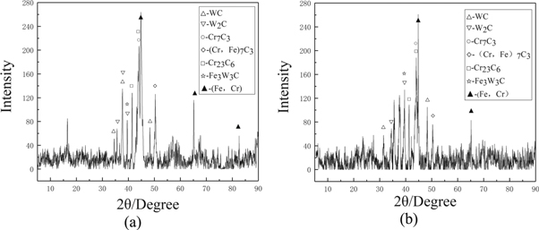
Figure 5. XRD diffraction pattern of the cladding layer (a) Irregular polyhedron WC particle reinforced Fe313 cladding layer (b) Spherical WC particle reinforced Fe313 cladding layer.
Download figure:
Standard image High-resolution imageAs can be seen from EDS results (tables 2 and 3), the main elements contained in the eutectic structure are Fe, Cr, and C. Furthermore, in the two coatings, the ratio that the sum of the number of Fe and Cr atoms to the number of C atoms is 2.436 and 2.784, respectively. This ratio is between 2.333 (7/3) and 3.833 (23/6). Therefore, combined with the XRD results, the carbide phases of the eutectic structure are Cr7C3, Cr23C6 and (Cr, Fe)7C3. We can use the phase transformation reactions in the Fe-Cr-C temary phase diagram to illustrate the formation of M7C3 and M23C6 phases therein: 
 Morever, due to the melting of WC particles, the C and W elements diffused into the matrix, which provided favorable conditions for the formation of carbides.
3.2. Microhardness analysis
Samples were carried out on a MH3 microhardness tester. Starting from the bonding line, every 0.3 mm distance is used as a gradient. Five times of microhardness measurement of the coating in each selected area, taking the average and calculating the standard deviation. The results are shown in figure 6: The hardness of the matrix of composite coating to which WC particles are added is significantly greater than that of the coating to which no WC particles are added. The reason mainly lies in the dissolution of WC, which combined with the Fe-base to produce many high hardness carbide phases. Moreover, the hardness of matrix of the irregular polyhedron WC particle reinforced Fe-based spray welding layer is greater than that of the spherical WC particle composite coating. The former Microhardness tests on spray welding has a maximum hardness of 864.7 HV0.2 and an average hardness of 764.7 HV0.2. The latter has a maximum hardness of 791.2HV0.2 and an average hardness of 725.6 HV0.2. Due to the morphology, the irregular polyhedral WC particles are more easily heated to a higher temperature state than the spherical WC particles, so that the irregular polyhedral WC particles are more melted. It more significantly improved the hardness of the matrix of composite coating. In addition, the microhardness from the bottom to the top of the coating initially showed a rising trend and then exhibited a downward tendency when reach a certain value. This is because the WC particles sink to a position close to the bonding line, so that the bottom and medium hardness of the coating is greater than the top. And due to the dilution of 45 steel on the coating, the hardness at the bottom is lower than that in the middle.
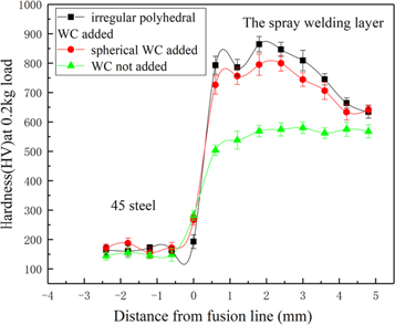
Figure 6. Hardness (HV) of the coating.
Download figure:
Standard image High-resolution image3.3. Wear resistance test
The equipment used in this friction and wear test was an MMG-10 end face friction and wear testing machine. The friction applied between the coating and the Cr12MoV, the normal applied load was 300 N, speed was 200 r/min, and duration was 1 h. Figure 7 shows the loss weight of the three samples. It can be seen from the figure that the weight loss of the coating without adding WC particles is the largest, and the weight loss of the coating to which spherical WC particles are added is the smallest. As can be seen from table 4, The wear resistance ε of the coating with adding irregular polyhedral WC particles is 1.9 times that of the case where the WC particles are not added, and the wear resistance of the coating with adding spherical WC particles is 1.28 times that of the coating with adding irregular polyhedral WC particles. The wear rate ω herein is the weight loss per minute of the sample, and the wear resistance ε is the reciprocal of the wear rate.
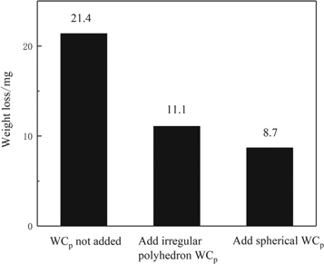
Figure 7. The weight loss after 1-h wear of the coating.
Download figure:
Standard image High-resolution imageTable 4. The abrasion resistance of the coatings.
| Weight loss(G) | Wear rate(ω) | Wear resistance (ε) | |
|---|---|---|---|
| materials | mg | mg/min | |
| No WC particles added | 21.4 | 0.357 | 2.801 |
| Add irregular polyhedron WC particles | 11.1 | 0.185 | 5.405 |
| Add spherical WC particles | 8.7 | 0.145 | 6.897 |
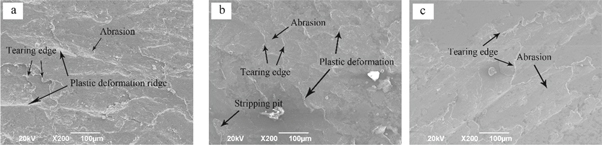
Figure 8 shows the surface topography of the sample. There were abrasions, stripping pits, tearing edge, and other typical adhesive wear characteristics observed. The adhesive wear is the main form of wear here. In the relative motion of the friction pair, the layer is subjected to compressive stress, shear stress and friction. The material removal stress is mainly the latter two, and the coating is plastically deformed in the surface and subsurface under the influence of both [12]. As the wear process progresses, the degree of plastic deformation of the subsurface of the layer reaches the limit, and then cracks occured at the subsurface of the coating rather than at the surface. These cracks expand and toward the surface, allowing the material to be removed in the form of exfoliation. For the coating without WC particles added, the surface hardness is low, the resistance to plastic deformation is weak, and the resulting peeling layer is large, which makes the wear more serious. For the composite coating with WC particles added, the WC particles play a role of support and protection, and the surface hardness is large, so the peeling layer is small and the wear is light. Moreover, the irregular polyhedral WC particles melt more in the layer than the spherical WC particles, which combined with the matrix to produce more high hardness carbides. These carbides are mainly present in the eutectic structure, and their microhardness of the layer is significantly improved, so that the hardness of the coating to which the irregular polyhedral WC particles are added is greater than the hardness of the coating to which the spherical WC particles are added. However, the wear resistance of these carbides is not as good as that of the WC particles [13], which causes the wear resistance of the composite coating to decrease. Therefore, the spray welding layer with adding spherical particles has the best wear resistance.
Figure 8. SEM image of the composite coatings under 1-h wear , (a) the coating without WC particles addition, (b) add irregular polyhedral WC particles, (c) add spherical WC particles.
Download figure:
Standard image High-resolution image
4. Conclusions
The conclusion of this paper is as follows:
- 1.WC particles with different shapes reinforced Fe-based coating was prepared by plasma welding. The irregular polyhedral WC particles melt more than the spherical WC particles, and the microstructure of composite coatings consisted of WC particles, eutectic microstructure, dendritic and the undissolved carbides.
- 2.Irregular polyhedral WC particles increase the hardness of matrix of composite coating more obviously, while spherical WC particles improve the wear resistance of composite coating more significantly. This is because the irregular WC particles are more melted, so the coating contains more high-hardness carbides present in the eutectic structure, which significantly increases the hardness of the matrix. The wear resistance of these carbides is worse than that of the WC particles, so the wear resistance of the coating is reduced. Therefore, the coating to which the spherical WC particles are added has better wear resistance.
Acknowledgments
The author acknowledges the financial support from the Key Technology R&D Program of Anhui Province (201904Aa05020084) , Industrial guiding fund of changfeng county and hefei university of technology and fund of Anhui Wanan Co.Ltd(W2019JSKF0210)