

Abstract
Ex-situ TiC reinforced Ni-based coating was fabricated via plasma transferred arc. This study focused on the relationship between the microstructure, microhardness and tribological properties of TiC/Ni-based coating with different Nb content. Results showed that Nb inhibited the dendritic microstructure formed by remelted TiC in the molten pool. Furthermore, the precipitation of M23C6 was affected dramatically by Nb content. When Nb content was 5 wt%, XRD and SEM results showed that M23C6 was strongly precipitated compared with the coatings with Nb content of 0 wt% and 10 wt%. M23C6, (Nb, Ti)C particles and solid solution film played an important role in tribological behavior, mainly reflected in improving the microhardness, wear resistance of the coating and reducing friction coefficient. The dry sliding wear test results showed that the reaction layer can inhibit the crack propagation between TiC and matrix, which is mainly attributed to the role of the reaction layer as the medium. The findings of this study would offer a valuable reference for TiC/Ni-based coatings to refine microstructure, improve interface adhesion between TiC and Ni-matrix, and enhance tribological properties.
Export citation and abstract BibTeX RIS
1. Introduction
Ceramic particles reinforced metal matrix composites (MMCs) coating has received great attention due to its good match between toughness and wear resistance [1]. Among various metal matrix composite coatings, the Ni-based coating has been widely applied in surface engineering industries as the matrix to enhance the abrasion resistance of large machinery parts such as tunneling equipment, rollers, internal combustion engine, etc [2–4]. Due to the presence of B and Si elements in Ni-based alloy powder, this reduces the melting point of the matrix. It is often called Ni-based self-fluxing alloy powder [5]. Hence, Ni-based alloy powder is a kind of matrix with excellent comprehensive properties such as lower melting point, wettability, wear resistance, and a modest price [6]. To further enhance the tribological properties of the Ni-based coating, some ceramic phase reinforcing particles such as WC [7], SiC [8], TiB2 [9] and TiC [10] are added to the matrix. As one of the carbide particles widely used in the coating of reinforced Ni matrix, WC has excellent physical and chemical properties [11]. Furthermore, WC and Ni matrix have excellent wettability or WC can react with the matrix to form a reaction layer, which plays a role in reducing the stress of the reinforcing phase and the matrix [12]. Compared with WC, TiC is regarded as a potential reinforcing particle with high melting point, high modulus, low density, good chemical compatibility, good high temperature oxidation and wear resistance [13].
Nevertheless, it is well known that the interfacial bonding strength between reinforcements and matrix is the one of the critical factors to control tribological properties of metal matrix composite coatings [14]. Lin et al reported that the wetting angle between the TiC and Ni matrix is ∼30° at 1653 K [15]. This restricts the application of TiC reinforced Ni-based coating. Hence, in order to give full play to the excellent physical properties of TiC, it is necessary to improve the wetting behavior of the TiC/Ni-based to enhance the interfacial bonding strength. Shen et al prepared ex situ TiC reinforced Inconel 625 composites via laser additive manufacturing. They found that an MC alloy reaction layer formed between matrix and TiC particles which improved the bonding strength of TiC and matrix [16]. Muvvala et al prepared ex situ TiC reinforced Inconel 625 materials and observed that MC (M: Nb, Mo) reaction layer was formed between the metal matrix and TiC [17]. It is a simple and effective strategy to improve the bonding strength of TiC and Ni matrix by adding trace strong carbide forming elements. The MC reaction layer formed in situ on the surface of unmelted TiC can act as a transition zone, thus enhancing the interfacial adhesion of matrix/reinforcing phase. In addition, TiC particles have recrystallization behavior in the molten pool and may form dendritic TiCp after remelting, which is unfavorable for mechanical properties [18, 19]. This still continues to explore and look for simple and efficient strategies to enhance the mechanical properties of metal matrix composites. Niobium, as a strong carbide forming element, plays an important role in refining the refine the dendritic austenite [20]. Unfortunately, there are few reports about niobium regulating the microstructure between TiC and Ni matrix. The prominent features of the present investigation are as follows: (i). Effect of Nb on microstructure evolution of TiC reinforced Ni-based coating; (ii). The feasibility of forming MC reaction layer in situ and the reaction behavior with unmelted TiC particles were investigated; (iii). Effect of Nb on tribological behavior of TiC reinforced Ni-based coating.
Compared with present high energy beam techniques, plasma transferred arc (PTA) technology has the advantages of good metallurgical combination, low cost, high heat input, high efficiency [21, 22]. Hence, PTA technology has been widely used in the production of the high-quality coating as an industrial standard. In addition, plasma arc to manufacture parts is becoming an important variant of additive manufacturing (AM) [23]. Plasma transferred arc technology was selected to prepare metal matrix composite coatings in this study. Phase compositions, microstructure evolution, microhardness and tribological behavior of the Nb optimized TiC/Ni-based coatings were investigated in detail.
2. Materials and methods
The commercially available powders (wt%) of 30% TiC + 70% Ni50, 30% TiC + 5%Nb + 60% Ni50 and 30% TiC + 10% Nb + 60% Ni50 were denoted as sample S1, sample S2 and sample S3. Gas-atomized Ni50 self-fluxing alloy powder (Shanghai Zhongzhou special alloy material co. LTD, China) with spherically shaped particles was used as the matrix (chemical composition: wt%: C 0.9, Cr 16, Si 4.5, B 3.6, Fe 3.5, Ni bal). TiC powders (Qinghe Fengye metal material co. LTD, China), Nb powders (Nangong Zhongzhou alloy material co. LTD, China) were used as reinforcements. Figure 1 shows the SEM image of the starting powders. Q235 mild steel (chemical composition: wt%: C ≤ 0.17, Mn ≤ 0.14, Si ≤ 0.35, S ≤ 0.035, P ≤ 0.035, Fe bal) was used as the substrate. The mild steel plate was polished with 200 mesh, 400 mesh and 600 mesh silicon carbide sandpaper, and then the surface of the mild steel plate was cleaned with anhydrous alcohol. Finally, the steel plate was dried in a drying box of 60 °C. DRF-3 plasma cladding equipment manufactured by Qingdao Haina, China, was used to produce the coating. The optimized PTA process parameters were shown in table 1. The metallographic specimens with the size of 10 mm × 10 mm × 10 mm were cut by the edm wire cutter. All specimens were grounded and polished according to metallographic standards. A mixture of HCl and HNO3 (VHCl: VHNO3 = 3:1) was used to etch the coating section, holding for the 60 s and 120 s, respectively.
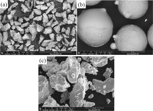
Figure 1. Shows the SEM image of the starting powders; (a) TiC powder. (b) Ni50 powder. (c) Nb powder.
Download figure:
Standard image High-resolution imageTable 1. Process parameters of PTA technology.
| Current (A) | Voltage (V) | Shielding gas | Scanning speed | Plasma gas |
|---|---|---|---|---|
| 105 A | 30 V | Ar (0.5 MPa) | 10 (mm s−1) | 0.7 (L min−1) |
The phase constituents of the coating were analyzed by x-ray diffraction (XRD, D/Max 2500PC Rigaku, λ = 1.5406 nm). The microstructure of the coatings was analyzed by Nova Nano SEM 450 produced by FEI (USA). Microhardness of coating cross section was carried out using an FM700 micro Vickers hardness tester under the load of 200 g, holding for 10 s. In order to determine the average microhardness value of the coating, ten points were measured successively from the top of the coating down in the measurement process, and the depth was about 1700 μm. The GETR-UMT-3 multi-functional wear tester was used to perform the room temperature reciprocating dry sliding test (time: 1800 s; load: 25 N; sliding velocity: 10 mm s−1; grinding ball: Al2O3; grinding ball diameter: 9.525 mm). During the reciprocating dry sliding test, the friction coefficient of the surface coating was recorded automatically by GETR-UMT-3 multi-functional wear tester. After the reciprocating dry sliding wear test, the volume loss of the wear mark area was measured via 3D shape analyzer (Zeta-20) produced by USA, and the average value of the three measurement results was the wear volume loss. The worn surfaces were observed by SEM.
3. Results and discussions
3.1. Phase analysis
Figure 2(a) shows the XRD diffraction pattern of the coatings. The diffraction peaks of the XRD pattern corresponding to γ-(Fe, Ni) [PDF:33-0397], TiC [PDF:32-1383], (Nb, Ti)C [PDF:47-1418] and M23C6. The diffraction peak of phase Nb was not detected in the diffraction pattern. This confirms that Nb melts and reacts with other elements in the molten pool during PTA cladding. With the increase of Nb content from 0 wt% to 10 wt%, the diffraction peak of M23C6 changes dramatically. At the diffraction angle of about 38° in figure 2(a), there is a diffraction peak of M23C6 in sample P2, which is not detected in sample S1 and S3. Generally, the forming elements of M23C6 mainly come from Ni50 alloy powder. Hence, the Nb content affects the behavior of alloying elements precipitated from the molten pool (discussed later).
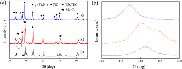
Figure 2. XRD pattern of the coating; (a) XRD results of composite coatings; (b) Local amplification of XRD pattern from 43° to 45°.
Download figure:
Standard image High-resolution imageFigure 2(b) shows the diffraction pattern of the local magnification mode of XRD from 43° to 45°, and the diffraction peak corresponds to γ-(Fe, Ni). According to  the smaller 2θ values indicate a larger interplanar crystal distance of the corresponding crystal planes [24]. This means that the γ-(Fe, Ni) crystal lattice is distorted during non-equilibrium metallurgical process. Table 2 shows the 2θ location and FWHM of the γ-(Fe, Ni) peak. It can be seen that there is a large deviation in the γ-(Fe, Ni) diffraction peak of sample S3. In other words, with the increase of Nb content in the coating, the matrix was transformed correspondingly. One of the most important roles in the phase evolution of coatings is the precipitation and solid solution of Cr23C6. From the XRD pattern, Cr is present in the coating in two forms. When the coating contains 5 wt% Nb, Cr is precipitated as carbide (Cr23C6). When the coating contains 10 wt% Nb, Cr is mainly dissolved in the austenitic matrix.
Table 2. 2θ location and FWHM of the γ-(Fe, Ni) peak.
| Sample | 2θ location (°) | FWHM (rad) |
|---|---|---|
| Standard | 44.011 | |
| S1 | 44.100 | 0.451 |
| S2 | 44.020 | 0.635 |
| S3 | 43.739 | 0.418 |
3.2. Microstructure of the coating
The SEM images of the cross-sectional of the coatings are shown in figure 3 and EDS results corresponding to feature areas in figure 3 are shown in table 2. The unmelted TiC particles, primary dendritic TiC, and spherical TiC are observed in figures 3(a)–(a1). According to previous literature, the formation of primary dendritic formed by recrystallization of TiC was harmful to the mechanical properties of MMCs [19]. In the current work, one goal is to avoid the formation of coarse primary dendritic formed by recrystallization of TiC by adding Nb element. The sizes of in situ TiC particles are approximately 3 ∼ 5 μm shown in figure 3(a1). As shown in figures 3(b)–(b1), the number of coarse primary dendrites decreased and two kinds of carbide with different contrast appeared when the Nb content is 5 wt%. Furthermore, a reaction layer formed at the interface between TiC and matrix. Combined with EDS results (EDS points C, D, and E), the content of each element in regular geometry particles is basically the same as that in the reaction layer. It is worth noting that, the carbides with low contrast are carbides with high Cr content, which can be determined as M23C6 according to EDS analysis results. This corresponds to the diffraction peak at about 38 degrees in the XRD pattern. Figures 3(c)–(c1) shows the SEM images of sample S3. It can be seen that the characteristic microstructure of sample S3 underwent further evolution compared with sample S1 and S2. In addition to the carbides generated in situ, a network microstructure distributed along grain boundaries is also found in figure 3(c). The mechanism of Nb content on the microstructure evolution of the original coating (sample S1) is discussed as follows:
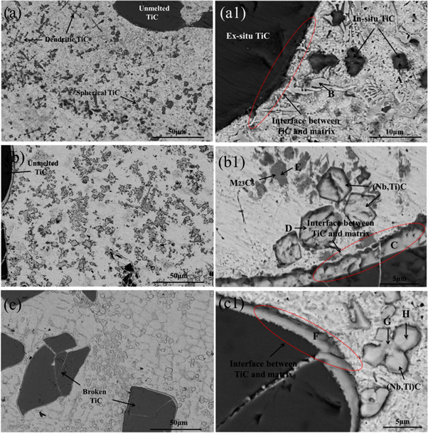
Figure 3. SEM images showing the characteristic morphologies with different Nb contents; (a) and (a1) 0 wt% Nb; (b) and (b1) 5 wt% Nb. (c) and (c1) 10 wt% Nb.
Download figure:
Standard image High-resolution imageAs known, the microstructure of carbide reinforced metal matrix composite materials can be affected by carbon content strongly [25]. In this study, the source of carbon provided by Ni-based alloy powder and partially recrystallized TiC. The increase of Nb content means more carbon consumption in the molten pool. Zhao et al studied the relationship between carbon content and tribological behavior of NbC/Fe-based coatings. They found that the evolution of NbC microstructure was closely related to C content [25].
Based on the analysis of microstructure features, the solidification and precipitation process in the molten pool is as follows: In the initial powder system, the melting point of Nb is lower than that of TiC but higher than that of Ni-based powder. TiC with a high melting point (3200 °C) did not melt completely in the molten pool, but partially dissolved at the liquid-solid interface. This is confirmed by the SEM image in figures 3(a)–(a1). Dissolved TiC provides a Ti source and a C source. TiC and NbC have similar lattice lattice constants, both Ti and Nb are strong carbide forming elements [26]. In the spontaneous nucleation process of MC alloy carbide, niobium and titanium atoms can replace each other in their respective positions in the lattice, thus precipitating out in the form of (Nb, Ti)C carbides. Hence, regular geometry (Nb, Ti)C particles were precipitated out first in the first stage. As the molten pool temperature decreases, the element Cr formed by carbide with the lower melting point was precipitated by M23C6 phase at the liquid-solid interface. Finally, unprecipitated carbide-forming elements remain in the solid solution, and a small amount of eutectic may be precipitated by the eutectic reaction. As can be seen from figure 3(a1), point B), a small amount of eutectic is distributed around the matrix.
3.3. Characteristic carbide precipitation behavior
It should be noted that the phase of M23C6 is significantly present in sample S2 shown in Figure 4, but not observed in sample S1 and sample S3. This corresponds well with the XRD results. It is well known that the presence of V, Cr, Mo elements often reduces the Ms point [27]. Similarly, the addition of Nb elements will also cause changes in the precipitation behavior of various substances in the system. With the increase of Nb content to 10 wt%, Nb and Ti atoms consume a large number of C atoms, resulting in carbon-poor behavior in the molten pool. Therefore, even if the pool system has a lower Ms point, the carbide-forming elements remain in the matrix or are expelled from the grain boundary after austenitizing due to insufficient nucleation of carbide. However, the addition of too much Nb into the Ni-based melt results in an increase in the viscosity of the molten pool [28]. This greatly reduces the overall rheological property of the molten pool. At the same time, in the process of plasma transferred arc scanning, there is a large temperature gradient at the top of the molten pool, which leads to the surface tension caused by Marangoni convection [9]. This, in turn, creates a thermal capillary flow on the surface of the molten pool, further destabilizing the rapid solidification process. Figure 3(c1) shows a high-power SEM image of in situ (Nb, Ti)C particles. It can be seen that carbide particles have a core–shell structure. EDS results show that the core has a high content of Ti elements, and the shell has basically the same content as the reaction layer.
There are three distribution forms of Nb atoms in the molten pool. ①: Nb is a strong carbide forming element, forms nucleation with Ti, C atoms which from the unmelted TiC to form (Nb, Ti)C in the molten pool. ②: The surface of the unmelted TiC particles in the molten pool provides an attachment point for free Nb atoms. Subsequently, a solid solution composed of Ti, Nb, Cr, and C is formed by a dissolution/precipitation mechanism [17]. It should be emphasized that EDS results in table 3 (EDS point: C-D, H-F,) show that the content of elements in the reaction layer is very similar to that in MC particle. There is basically no difference between the composition of the reaction layer and MC particles. It is also shown from the side that the formation of the reaction layer and the particles precipitate out at the same solidification stage. And the distribution of the reaction layer on the surface of the unmelted TiC particles is random. The formation of in situ film has a strong interface with the matrix, which enhances the bonding force between the TiC and the matrix (discussed later). Theoretically, both the microstructure of the remelted TiC and the interfacial adhesion of the unmelted TiC are improved. ③: The coating prepared by plasma transferred arc is formed by rapid non-equilibrium solidification process. Some carbide-forming element atoms fail to fully nucleate, but are solids dissolved in the matrix. This will cause certain component segregation. As the temperature is reduced to phase transition point, in order to reduce the shear resistance during the phase transition, alloying elements is discharged to the matrix [29]. Hence, a small amount of Nb exists in the matrix or grain boundary in the form of a solid solution.
Table 3. Chemical composition (at%) of different regions marked in figure 3.
| EDS point | Ti | Nb | Cr | C | Fe | Ni | B |
|---|---|---|---|---|---|---|---|
| A | 31.82 | — | 00.51 | 66.62 | 00.52 | 00.52 | — |
| B | 00.29 | — | 04.90 | 48.43 | 12.97 | 03.73 | 29.67 |
| C | 14.54 | 08.63 | 00.30 | 76.23 | — | 00.30 | — |
| D | 14.87 | 09.58 | 00.39 | 74.58 | — | 00.58 | — |
| E | 03.20 | — | 39.75 | 52.63 | 00.87 | 03.56 | — |
| F | 14.93 | 09.72 | — | 74.92 | 00.43 | — | — |
| G | 18.95 | 10.69 | — | 69.80 | 00.55 | — | — |
| H | 14.04 | 10.74 | 00.21 | 74.36 | 00.66 | — | — |
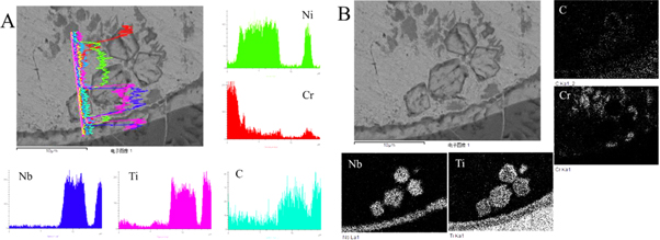
Figure 4. SEM images showing the EDS line scan and elements mapping of the sample S2; (A) EDS line scan. (B) EDS elemental mapping.
Download figure:
Standard image High-resolution imageFigure 5 shows the SEM image of the carbide characteristic morphology. In order to obtain the fine microstructure image of the coating, the etching time of the sample was 120 s before SEM observation. It can be seen from figure 5(a) that the in situ formation of (Nb, Ti)C particle is octahedral structure. Figure 5(b) depicts the independently grown petal-shaped M23C6. Figure 5(c) shows the core–shell structure and in situ morphology of (Nb, Ti)C particles. The addition of Nb strongly regulates the microstructure of the original coating. Fine dispersion distribution of (Nb, Ti)C particles, petal-like M23C6 and unmelted TiC particles with reaction layer are used as the reinforcing phase of the coating. The austenitic matrix provides good toughness, which is conducive to the construction of perfect metal matrix composites. The goal of making full use of the performance of each phase is achieved as far as possible.
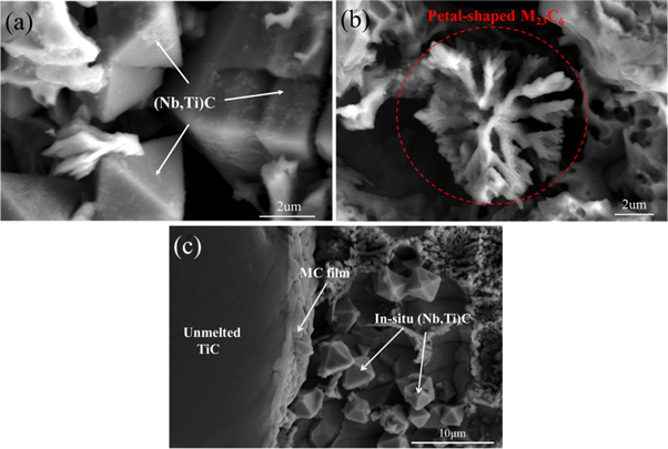
Figure 5. SEM image of carbide characteristic morphology; (a) (Nb, Ti)C particles in sample S2; (b) Petals shape of M23C6 in sample S2; (c) Reaction layer in sample S3.
Download figure:
Standard image High-resolution image3.4. Microhardness of the coatings
Figure 6 shows the average microhardness values of the coatings with different Nb contents. It can be seen that sample S2 has the highest microhardness in all samples. The main enhancement contribution of microhardness is derived from the formation of the hard phase [4]. According to XRD result and SEM image, finely dispersed (Nb, Ti)C and M23C6 particles are the main source of contribution to the increase in microhardness of sample S2. When the Nb content reaches 10 wt% in the coating (sample S3), the microhardness is lower than that of the sample S1. Based on the above description, the reason for the decrease in microhardness of sample S3 is mainly attributed to the insufficient carbon content, which leads to insufficient nucleation of carbide forming elements.
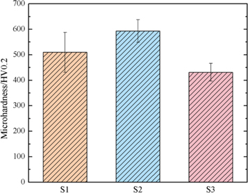
Figure 6. Microhardness values of coatings with different Nb contents.
Download figure:
Standard image High-resolution image3.5. Tribological behavior
Generally speaking, the friction coefficient of the metal materials varies with the normal load. Hashempour et al studied the relationship between different normal loads and friction coefficients of metal materials. They found that the friction coefficient of the material increases as the load decreases [30]. The obvious COF decrease by load increase can be explained by the formation of mechanically mixed layer (MMLs) [31, 32]. When the loading force is applied on the material surface, the plastic deformation of the material results in the work hardening behavior. When the load is not enough to induce the random deformation of the material, the friction coefficient between the pairs is larger. When the load causes the material to undergo plastic deformation, the existence of the plastic deformation zone makes the pair of pairs relatively smooth, so it shows a lower friction coefficient. Cao et al also studied the relationship between different normal loads and friction coefficients of metal materials. They found that as the normal load increased from 20 N to 100 N, the corresponding coefficient of friction decreased from about 0.8 to 0.65 [33]. Figure 7 shows the friction coefficient (COF) of different samples. It can be seen from figure 7 that the three coatings exhibit different friction coefficient variation behaviors under 25 N loading. As the 25 N load cannot make sample S1 and sample S2 have enough plastic deformation behavior, they finally show a higher friction coefficient behavior. However, the friction coefficient of sample S3 decreases sharply. It is possible that work hardening behavior occurred in the friction process with S3, and the coating surface was compacted, thus showing a lower friction coefficient.
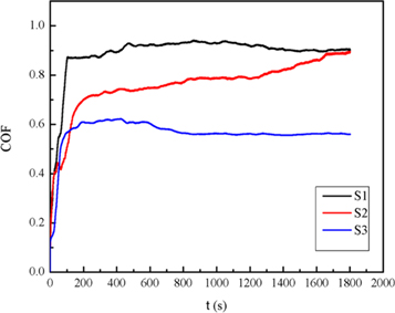
Figure 7. The friction coefficient of different samples.
Download figure:
Standard image High-resolution imageFigure 8 shows the wear volume loss of each samples. With the increase of Nb content to 10 wt%, the wear volume and friction coefficient increase, which is unfavorable to the tribological properties of the coating. The main reason for this result is the carbon poor behavior in the coating, so the carbides formed are metastable structures, which can be expressed as (Nb, Ti)C(1−x), x < 1.

Figure 8. The wear volume and friction coefficient of different samples.
Download figure:
Standard image High-resolution imageIn order to discuss the tribological behavior of coatings more specifically, figure 9 shows the SEM morphology of the wear scar after dry sliding friction. The most two important factors that influence the mechanical property of the MMCs are the matrix microstructure and the carbide particles. It is well known that carbide reinforcing phase carries and resist the effects of applied loads during wear test due to their high hardness until failure occurs. Meanwhile, the soft matrix binds the carbide particles and transfers the external load to individual carbide particles [17]. Therefore, the good compatibility between the matrix and the hard carbide particles is the key to the material's full play. The matrix will be quickly damaged when the TiC peels off and fails to exist the effects of applied loads. This result is harmful to improving wear resistance. Figure 9(a) shows that the unmelted TiC particles remain relatively shape at the junction of the worn and unworn areas, but cracks around the TiC particles appear at the junction of TiC and the matrix. This indicates that under the action of the load, the interface with low bonding strength fails before the TiC particles fail. The end result will cause the TiC particles to flake off. Figure 9(b) shows the TiC particles in the worn area are broken but no cracks appear at the interface. Figure 9(c) further shows that when the unmelted TiC is broken, there is still a continuous binder phase at the interface between TiC and the matrix. Figure 9(A) shows the EDS results of marked points. The results show that the continuous binder phase is a solid solution composed of Ti, Nb, Cr, and C. This also proves that the film formed surrounding TiC particles has the effect of enhancing the interface bonding force. In this work, the microcracks first originated from the stress concentration tip of the dendritic structure and the defect of the reinforcement/matrix, and it is more likely to induce microcracks than the dendritic structure at the defect of the reinforcement/matrix. The solid solution film attached around the TiC particles has the function of the in situ method, that is, the interface of the reinforcement/matrix is a stronger interface. It is worth mentioning that, as far as the authors know, this method has a certain reference value for laser cladding technology.

Figure 9. SEM images showing the worn morphologies. (a) No Nb; (b) With Nb; (c) characteristic morphology of (b); (A) (B) EDS results of marked points in figure 9(c).
Download figure:
Standard image High-resolution image
4. Conclusions
The feasibility of adding Nb to optimize the microstructure and tribological behavior of TiC/Ni-based was studied, which might be helpful for other high energy beams prepared Ni-based wear - resistant coatings. The main conclusions are drawn as follows:
- (1)When Nb content is 0 wt% and 10 wt% respectively, the phase of coating is both γ-(Fe, Ni) and MC. When Nb content is 5 wt%, the phase of coating is γ-(Fe, Ni), MC and M23C6. Adding 5 wt% Nb helps Cr to precipitate out of the matrix and form carbide.
- (2)With the addition of Nb, the formation of dendritic TiC is inhibited, and (Nb, Ti)C particles are formed. Compared with the TiC/Ni-based coating, when the Nb content was 5 wt%, the wear resistance of the coating was improved by about twice.
- (3)When the Nb content is 0 wt%, the dry sliding friction test results show that cracks are generated at the interface between TiC and the matrix. With Nb added, the formation of a solid solution film surrounding unmelted TiC particles enhances the force of interfacial adhesion.