

Abstract
Cr12MoV alloy steel was nitrided in a plasma chamber with and without an auxiliary cathode. The results indicate, that at an appropriate distance between the auxiliary cathode and the alloy steel, hollow cathode discharge (HCD) is generated. The HCD is effective and important to harden the alloy steel by promoting the formation of a harder and thicker nitrided layer, which not only contains a nitrogen diffusion zone, where nitridation of the chromium carbide of the alloy occurs as in the case without auxiliary cathode, but also a top compound layer. The distance between the auxiliary cathode and the alloy steel noticeably affected the plasma nitriding kinetics of the Cr12MoV alloy steel. As the distance increases, the thickness of the compound layer and the microhardness of the nitrided layer increase first followed by a decrease. The nitridation mechanisms of the alloy steel with and without auxiliary cathode are discussed.
Export citation and abstract BibTeX RIS
1. Introduction
Plasma nitriding, also known as glow discharge nitriding, is a thermochemical treatment process for improving the hardness and resistance against wear and corrosion of metals [1–6]. Compared with traditional gas nitriding, plasma nitriding is a more efficient method to harden the surface of metals and alloys by increasing the number of active nitrogen atoms and consequently the chemical potential of nitrogen for nitriding. Plasma nitriding has been widely used for ferrous tools and dies, continuously subjected to harsh environments. A typical nitrided layer of the ferrous materials is composed of a compound layer and a diffusion zone [7]. The former mostly contains iron nitrides, such as γ'-Fe4N, ε-Fe2–3N phases, or a mixture of both. The latter, located below the compound layer, is a solid solution, in which nitrogen atoms occupy interstitial positions in the ferrite matrix. The phase composition and the microstructure of the nitrided layer are mainly determined by processing parameters such as temperature [8], time, and atmospheric composition [9, 10]. Generally, higher nitriding temperatures and longer nitriding times promote the formation of a thicker and harder nitrided layer. The effect of the atmospheric composition is mainly due to the increasing nitrogen content in the atmosphere, which promotes the formation of the compound layer and the diffusion zone. The fundamental reason is the increase in nitrogen potential in the nitriding atmosphere.
The formation of the nitrided layer can be further promoted using hollow cathode discharge (HCD), an enhanced glow discharge through adding an auxiliary cathode to assist to ionize the nitrogen-containing gas for nitridation. It has been reported that the plasma density generated by HCD can be increased by 2–3 orders of magnitude [11], which inevitably increases the nitrogen potential during nitridation. Ahmadi et al [12] found that by HCD assistance, the nitrogen concentration at the surface of the TiAl alloy increased up to ∼40%, resulting in the formation of a nitrided layer with its thickness increased by a factor of ∼20. Thus far, two major types of HCD plasma nitriding units have been used: independent HCD unit or auxiliary cathode. The former, based on either radio frequency plasma technique [13] or active screen technique [14], generates a high-intensity plasma typically in a cathode tube or in a cathode consisting of two coaxial cylinders. The auxiliary cathode assisted nitriding method generates a high-density plasma in the space between the auxiliary cathode and the sample intended to be nitrided [12, 15, 16].
It is well known that good tribological and anticorrosion properties can be attributed to the compound layer, while the improvement in the fatigue resistance is caused by the diffusion zone [17]. A reasonable matching of thickness or hardness of the compound layer and the diffusion zone is beneficial to improve the performance of the nitrided layer [18, 19]. Therefore, it is necessary to appropriately regulate the phase composition and the microstructure of the nitrided layer. At present, most of studies on HCD-assisted plasma nitriding focus on the HCD-generated high nitrogen potential to improve nitriding efficiency, while research on the regulation of the nitrided layer has been limited. Generally, the HCD behavior is affected by the hollow cathode (HC) structure (cavity, hole, or parallel faces), gas species and pressure, discharge voltage, as well as cathode material [11, 20–23]. Among them, the most important factors are the gas pressure and the distance between opposite cathodes (or the inner diameter for a tubular cathode). The product of the gas pressure and the distance needs to be controlled within a given range to ensure the stability of the HCD [11, 23, 24]. The variability of the above two parameters provides a possibility to regulate the nitrogen potential during plasma nitriding.
In this work, an auxiliary cathode was used in the plasma nitriding process of a Cr12MoV alloy steel, which is the designation of a cold-work steel in the national standard GB1299 in China and is similar to D2 (AISI) in USA and SKD11 in Japan. The size of the HC was varied by adjusting the distance between the auxiliary cathode and the sample. Based on the study of the effect of the auxiliary cathode on the nitriding behavior of the steel, our aim was to develop a method for plasma nitriding, which enables the control of the phase composition and microstructure of the nitrided layer with high efficiency.
2. Experimental
2.1. Material
Samples with dimensions of 20 mm × 10 mm × 2 mm were cut off from a Cr12MoV alloy steel plate; their chemical composition is shown in table 1. All samples were polished using 1000-grit SiC paper and then ultrasonically cleaned in acetone for nitriding.
Table 1. Chemical composition of Cr12MoV alloy steel (wt%).
| C | V | Cr | Mo | Si | P | S | Fe |
|---|---|---|---|---|---|---|---|
| 1.53 | 0.20 | 11.59 | 0.40 | 0.40 | 0.022 | 0.025 | Bal. |
2.2. Plasma nitriding process
The plasma nitriding was carried out in a DLZ-10/10/20 semi-industrial pulsed-DC plasma nitriding apparatus, shown schematically in figure 1(a). The apparatus consisted of a 1 kHz square wave pulsed-DC power supply and a heating system to increase the temperature up to 1000 °C by radiation. The sample was attached to a carbon steel cathode disc by a Cr12MoV alloy steel holder with a thickness of 10 mm for nitriding. At the same time, a Cr12MoV alloy steel plate with dimensions of 40 mm × 40 mm × 5 mm was placed opposite to the sample as an auxiliary cathode to form an HC. After the chamber was evacuated to a pressure lower than 3 × 10⁻¹ Pa and subsequently filled with argon, the sample was heated to the temperature over 300 °C at a pressure of 200 Pa and cleaned by argon sputtering for 15 min at a pressure of 60 Pa using a cathode voltage of −900 V with duty cycle of 10%. Then, the atmosphere was switched to ammonia gas. The samples were nitrided for 4 h at a pressure of 100 Pa, voltage of −650 V, duty cycle of 50%, and temperature of 550 °C. A WDL-31 infrared thermometer was used to measure the temperature of the sample.

Figure 1. Schematic diagrams of (a) the plasma nitriding apparatus and (b) the discharge around sample.
Download figure:
Standard image High-resolution imageWhen the auxiliary cathode is positioned at an appropriate distance (d) from the sample, HCD occurs between them as shown clearly in figure 1(b). This promotes the nitridation of the sample in the case when the above nitriding parameters were not varied. To investigate the effect of the auxiliary cathode on the plasma nitriding, the Cr12MoV samples were nitrided at distances d in the range of 6–24 mm. For comparison, the sample was also nitrided without the assistance of the auxiliary cathode.
2.3. Characterizations
The morphologies and microstructures of the alloy steel samples before and after nitriding were investigated using optical microscopy (OM), x-ray diffraction (XRD) and grazing incidence x-ray diffraction (GIXRD), field-emission scanning electron microscope (FE-SEM)/x-ray energy-dispersive spectroscopy (EDS), electron probe micro-analyzer (EPMA), and transmission electron microscopy (TEM). The samples for OM analysis were etched in 4% nitric acid alcohol solution. Microhardness tests were conducted using a HV-1000 instrument with a load of 50 g and dwell time of 10 s. At least five readings were taken to obtain each average hardness value.
3. Results and discussion
3.1. Microstructure of Cr12MoV alloy steel
The XRD pattern shown in figure 2(a) indicates that the Cr12MoV alloy steel consists of α-Fe matrix and Cr7C3-type carbides. These carbides, which appear as bright areas under OM, nearly form a carbide network, as shown in figure 2(b). They exhibit a grayer contrast in figure 2(c), a SEM image in backscattered electron (BSE) mode. It shows that the sizes of the carbides are in the range of one micron to dozens of microns. The EDS analysis indicates that the carbides contain major Fe and Cr and minor V.

Figure 2. Phase composition and microstructure of the as-received Cr12MoV alloy steel: (a) XRD pattern, (b) OM image, and (c) BSE-SEM image.
Download figure:
Standard image High-resolution image3.2. Plasma nitridation with and without auxiliary cathode
Figure 3 shows the GIXRD results of the Cr12MoV alloy steel nitrided for 4 h without and with the auxiliary cathode at a distance d = 8 mm from the sample. The top surface of the alloy steel nitrided without the auxiliary cathode is composed of major γ'-Fe4N, CrN, and minor α-Fe(N) phases. When using the auxiliary cathode during the nitriding process, major ε-Fe2–3N and minor γ'-Fe4N phases appear, which indicate that the auxiliary cathode assistance promotes the nitridation of the alloy steel.

Figure 3. GIXRD patterns of the Cr12MoV alloy steel nitrided without and with auxiliary cathode (d = 8 mm).
Download figure:
Standard image High-resolution imageAfter 4 h of nitridation without auxiliary cathode, the Cr12MoV steel forms a nitrided surface layer with a thickness of ∼40 μm. The etched nitrided layer exhibits darker contrast under OM as shown in figure 4(a). Figure 4(b) shows a BSE-SEM image of the nitrided layer in a higher magnification. The appearance of large particles in deeper areas is the same in grayscale as that of the original carbides (figure 2(c)), while those in a shallow depth developed a deeper gray contrast due to nitridation. This indicates that the original large carbide particles were fully nitrided in the shallow area but not in the deeper. Figure 4(c) shows a magnified view of the framed area in figure 4(b), indicating that the periphery of large carbide particles, which, apparently were not been nitrided, is converted into nitrides, resulting in the deeper gray contrast as indicated by the arrows. However, the fine carbide precipitates of around and below 1 μm in the ∼40-μm-thick nitrided layer, were converted to deeper gray particles, suggesting that they were nitrided.
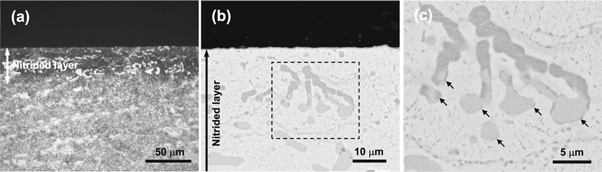
Figure 4. Cross-sectional morphologies of the Cr12MoV alloy steel nitrided without auxiliary cathode: (a) OM image, (b) BSE-SEM image, and (c) a magnified view of the framed area in panel (b).
Download figure:
Standard image High-resolution imageFigure 5(a) shows an OM view of the cross-sectional microstructures of the etched Cr12MoV alloy steel after nitridation for 4 h with the application of the auxiliary cathode (d = 8 mm). The auxiliary cathode assistance results not only an increase in the thickness of the nitrided layer from ∼40 μm to ∼80 μm, but it also changes its microstructure, which lies in two aspects. First, a top compound layer with a thickness of 10.8 μm occurs, which can be identified as mainly ε-Fe2–3N by GIXRD characterization. Second, the deeper area exhibits certain new 'veins' with a color contrast similar to that of the surface nitrided layer. These features of the compound layer and vein-like phases can be seen more clearly in figure 5(b), which shows the BSE-SEM image of the nitrided layer in higher magnification. Moreover, different from the nitridation without auxiliary cathode, apparently the original large carbide precipitates were nitrided, forming nitrides with deeper gray contrast.
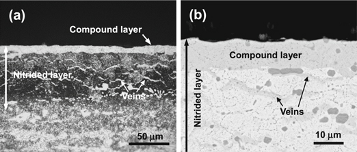
Figure 5. Cross-sectional morphologies of Cr12MoV alloy steel nitrided with auxiliary cathode at d = 8 mm: (a) OM image and (b) BSE-SEM image.
Download figure:
Standard image High-resolution imageFigure 6 shows a comparison of the backscattered electron image (BEI) and corresponding x-ray elemental mappings of the Cr12MoV alloy steel nitrided without and with auxiliary cathode at a distance of d = 8 mm from the sample. A ∼40-μm-thick nitrided layer rich in N is visible on the alloy steel nitrided without auxiliary cathode (figure 6(a)). In addition, there is an area richer in N in the nitrided layer, as indicated by an arrow. This is undoubtedly due to the nitridation of the large Cr7C3-type carbide precipitates in shallow depth. No N signals were observed from the carbide precipitates below the nitrided layer, which implies that the precipitates in the deeper area were not nitrided. Under the assistance of the auxiliary cathode, the nitrided sample formed a much thicker (∼80 μm) nitrided layer, within which a thin top layer formed richer in N (figure 6(b)). The top layer nearly contains only N and Fe, in agreement with the GIXRD characterization indicating that major ε-Fe2–3N formed there. Below the ε-Fe2–3N layer, a number of veins rich in C appear. The veins result from the decomposition of large carbide precipitates by nitridation, which is detailed later. The comparison of results suggests that the nitridation behavior of the Cr12MoV became different under assistance of the auxiliary cathode.

Figure 6. BEI and corresponding EPMA elemental mapping results for the cross section of the Cr12MoV alloy steel nitrided (a) without and (b) with the auxiliary cathode (d = 8 mm).
Download figure:
Standard image High-resolution imageFor the better understanding of the effect of the auxiliary cathode on nitridation, the microstructure of the nitrided layer below the top compound layer was further characterized by TEM. Figure 7 shows a TEM bright-field (BF) image of such region, in which the phase compositions on the specific locations of 1, 2, and 3 were identified by selected area electron diffraction patterns (SAEDP). The formation of Cr2N (figure 7(b)) at location 1, suggests the presence of the original carbide precipitate. Cr2N is formed due to incomplete nitridation of the carbide precipitates in larger size or in deeper area. This nitridation releases numerous C atoms, which diffuse preferentially along the grain boundaries where they react with Fe, precipitating veins of Fe3C on location 2 (figure 7(c)). The major area around the Cr2N particles and Fe3C veins, such as in location 3, is α-Fe(N) phase (figure 7(d)). Its formation results from the penetration of a small amount of N into the ferrite phase of the alloy steel.
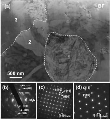
Figure 7. (a) Bright field TEM image of the nitrided layer in the case of the application of the auxiliary cathode with d = 8 mm and the corresponding SAEDPs of (b) location 1, (c) location 2, and (d) location 3.
Download figure:
Standard image High-resolution imageThe auxiliary cathode-assisted promotion of the plasma nitriding kinetics significantly affects the hardening of the Cr12MoV, as can be seen from the microhardness depth profiles shown in figure 8. For the alloy steel nitrided without the auxiliary cathode, the microhardness decreased slowly from 840 HV at the surface to 770 HV at the depth of 20 μm and then decreased rapidly to 287 HV at the depth of 60 μm, which is a value close to the hardness of the area without nitridation. In contrast, the alloy steel nitrided with the auxiliary cathode (at d = 8 mm) became harder. Its surface microhardness reached 1270 HV. The value slowly decreased to 923 HV at the depth of 40 μm and then quickly reached the hardness of the unnitrided area at the depth of 80 μm.

Figure 8. Microhardness profiles of the Cr12MoV alloy steel nitrided without and with auxiliary cathode (d = 8 mm).
Download figure:
Standard image High-resolution image3.3. Effect mechanism of the auxiliary cathode
The nitriding process of the Cr12MoV alloy steel without the auxiliary cathode can be described by a well-known model [1, 25]. The glow discharge decomposition of ammonia first occurs, generating N and H ions, which are accelerated by the electric field to bombard the alloy steel surface, sputtering Fe atoms. The Fe atoms are then combined with the active N atoms in the plasma, forming FeN species. A part of them are subsequently backscattered toward the sample and partly deposited on it, where they are decomposed to release N atoms. The inward penetration of the N atoms consequently forms the nitrided layer.
In contrast, the enhanced ammonia glow discharge process by the auxiliary cathode increases the concentration of the N active atoms, i.e., the nitrogen potential for nitriding. This results in the formation of a compound layer, which has not been observed in Cr12MoV alloy steels nitrided without auxiliary cathode. In that case, it appears mainly as γ'-Fe4N, which is a nitride with lower molar concentration of nitrogen. At the same time, the high nitrogen potential results in the nitridation of large Cr7C3-type carbide precipitates in the alloy steel, releasing a number of C atoms. Then, they diffuse along the grain boundaries where they react with Fe to form Fe3C 'lines'. The lines become waved vein-like, possibly because their formation is affected by the compressive strains generated during the nitridation.
The auxiliary cathode effect is closely related to the distance d between the auxiliary cathode and the Cr12MoV alloy steel. As can be seen in figure 5(a), an ∼80-μm-thick nitrided layer with a 10.8-μm-thick compound layer on its top was formed on the alloy steel at d = 8 mm. When d decreased from 8 to 6 mm, no significant nitrided layer could be observed by OM under the same magnification (figure 9(a)). A higher magnification under SEM in the BSE mode (the inset in figure 9(a)) reveals that only the carbide particles located near the sample surface were partially nitrided and consequently converted into a darker gray color contrast. When d increased from 8 mm, no significant variation could be seen in the thickness of the nitrided layer; however, the thickness of the compound layer decreased from 10.8 to 8.7 μm at d = 10 mm (figure 9(b)) and further to 4.9 μm at d = 24 mm (figure 9(c)). The dependence of the thickness of the compound layer on d is shown in figure 10. It is assumed that the ε-Fe2–3N phase forms when nitrogen concentration exceeds the solid solution limit of the steel substrate during the nitriding process. Once the ε-Fe2–3N phase develops a continuous layer, the nitridation process is controlled by the diffusion coefficient of nitrogen within the nitride layer. The diffusion coefficient of nitrogen depends highly on the nitrogen potential, i.e., the plasma density in the HC. As can be seen in figure 10, the highest plasma density was formed at d = 8 mm. As d increased from 8 to 24 mm, the plasma density slowly decreased; however, when d decreased from 8 to 6 mm, the plasma density sharply decreased. The dependence of the effect of the auxiliary cathode on d can be interpreted as follows.
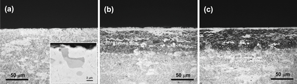
Figure 9. Cross-sectional morphologies of the Cr12MoV alloy steel nitrided using the auxiliary cathode at (a) d = 6 mm, (b) d = 10 mm, and (c) d = 24 mm.
Download figure:
Standard image High-resolution image
Figure 10. Dependence of the thickness of the compound layer on distance d.
Download figure:
Standard image High-resolution imageFormation of the compound layer in the case when d varies from 8 to 24 mm indicates the generation of high-density plasma, which indicates that HCD occurred. An indirect evidence is the significantly higher glow brightness in the HC under these conditions than that in the case without the auxiliary cathode, even though the brightness decreases with the increase in d. During the HCD-assisted plasma nitriding process, the same negative potential was applied to the auxiliary cathode and the sample. Several electrons oscillate between repelling potential of the sheaths at opposite walls in the cathode (the auxiliary cathode and the steel). Compared with the conventional glow discharge between parallel plates, the number of ionization and excitation events of gas atoms due to electron collision is significantly increased in the HC (the so-called pendulum effect [26–29]). In particular, a large number of doubly charged gas ions are produced, resulting in a significant increase in the plasma density and plasma current [11]. However, the oscillating electrons also move toward the anode (chamber wall) due to the electric attraction from the anode [29–31] and some of them can escape from the HC. As d increases, the amount of the escaped electrons increases due to the weakening of the electrostatic confinement in the HC, resulting in the decrease in the number of ionization and excitation events and consequently, the decrease in the plasma density. In other words, as d increases from 8 to 24 mm, the nitrogen potential in the HC gradually decreases, resulting in a gradual decrease in the thickness of the compound layer (figure 10). When d decreases, the electrons emitted from the sample are decelerated in the sheath of the auxiliary cathode too quickly to induce full and efficient ionization and excitation of the gas. Consequently, a dark gap appeared in the HC, in which the intensity of the produced glow discharge plasma was even lower than that in the case without auxiliary cathode. Therefore, this is probably the reason that no significant nitridation layer can be formed at d = 6 mm.
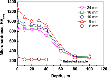
The d-dependent variation of the nitrogen potential for nitriding correspondingly results in a change in the microhardness of the nitrided layer on the Cr12MoV alloy steel, as shown in figure 11. Under the condition of d = 8 mm, the nitrogen potential in the HC reaches the maximum level. In this case, the compound layer has the maximum thickness, while the nitrogen content in the diffusion zone needs be the maximal as well. Therefore, the nitrided layer has the maximum surface hardness of 1270 HV and the hardest diffusion zone. The hardness decreases with the increase in d as a result of a decrease in the nitrogen potential for nitriding. The hardness of the alloy steel nitrided at d = 6 mm is only slightly higher than that of the untreated sample. The result can be attributed to the fact that the nitrogen potential becomes extremely low due to the dark gap formation in the hollow cathode as discussed above.
Figure 11. Hardness profiles of the Cr12MoV alloy steel nitrided using the auxiliary cathode at different d distances.
Download figure:
Standard image High-resolution image
4. Conclusions
Based on our results, the following main conclusions can be drawn.
- (1)The application of an auxiliary cathode in plasma nitriding produces HCD, which effectively and significantly increases the nitriding kinetics of the Cr12MoV alloy steel at 550 °C, inducing the formation of a thicker nitrided layer with a thin compound layer on its top surface.
- (2)The plasma nitriding kinetics of the Cr12MoV alloy steel can be noticeably affected by the distance between the auxiliary cathode and the alloy steel. A nitrided layer with the thickest compound layer and the hardest surface can be achieved by positioning the alloy steel for nitriding at an appropriate distance from the auxiliary cathode. In contrast, the auxiliary cathode has an unfavorable effect on nitriding if the alloy steel is positioned sufficiently close to the auxiliary cathode.
Acknowledgments
This work was supported by the National Key Research and Development Program of China, Grant No. 2016YFB1100203.