

Abstract
Coating processes are of great importance for protecting the materials used in the industry from the damaging effects of external environments and mechanical forces. There are a wide variety of coating methods, but the electrochemical deposition method within them is one step ahead because of its low cost, easy manufacturability and rapidity. Ni–B coatings have been produced for many years by the electroless deposition method, but electrodeposited Ni–B coatings are a relatively new research topic and attract much attention in recent years. Due to its superior properties Ni–B alloy coatings are successfully used in many industries such as aerospace, automotive, petrochemical, chemical and electronics. Works on reinforcing Ni–B alloys with second phase particles to increase these properties to a better level has been increasing rapidly in recent years. Ni–B alloy and composite coatings were investigated in this study. Furthermore, the bath components, production parameters, contents and properties of Ni–B alloy matrix composite coatings were presented comparatively. It was revealed that reinforcing the Ni–B alloy matrix with ceramic particles affected properties such as crystal structure, morphology, hardness, corrosion and abrasion resistance very seriously.
Export citation and abstract BibTeX RIS
This article was updated on 06 June 2021 to add permission lines to the figures.
1. Introduction
Parts used in industrial factories are subjected to abrasion and high corrosion. The damage caused by the simultaneous effect of wear and corrosion on the surface of the machine parts is much heavier than the damage that would occur if these two effects moved separately. This compound effect causes severe damage to various industries such as energy production, mining, chemical manufacturing, paper production [1]. Rather than improving the properties of the entire material used in most applications, improving the properties of the material surfaces exposed to mechanical forces and corrosive environments presents a more economical and practical approach to the problem. Surfaces of various engineering materials used in the industry can be successfully improved with many techniques. One of the most techniques used is the electrochemical coating technique. In this technique, the metals or alloys are generally electrochemically coated on a surface by electric current in a dense, smooth and adherent form [2]. The electrodeposition technique is a preferred method for producing coatings due to control of production parameters in a wide range, low cost, ability to obtain more compact structures, high purity, its rapidity, no need for heat treatment, easy producibility [3]. Continuous efforts are being made by researchers to find out alternatives to traditional materials and to improve the materials performance, and these efforts have led to the development of composite systems. Co-deposition of the second phase particles into the metal or alloy matrix allows the production of composite materials with unique properties and a wide range of products. Metal-matrix nanocomposite materials have many advantages compared to conventional monolithic alloys, and these materials can be successfully applied to many engineering materials. In electrochemical metal matrix composite coatings, all metals and alloys that can be deposited electrolytically for matrix material can be used, and a variety of hard ceramic particles such as oxides, carbides and nitrides can be used as reinforcement elements [4]. The reinforcement of the second phase particles improves properties of tribology, hardness, abrasion and corrosion resistance [3].
Nickel-boron alloy coatings, which are frequently preferred as matrix materials in research on electrodeposited nanocomposite coatings in recent years, have good anti-corrosion properties, high abrasion resistance (better compared to hard chrome platings) and high hardness. Nickel-boron alloy coatings are used in industries such as petrochemical, automotive, electronics, space, nuclear, paper, plastics, optics, textiles, food and printing, computer [5]. However, in parallel with the new developments in technology, higher performance than industrial parts is expected for more demanding requirements [6]. The performance properties of metals or alloys may remain at limited levels, but the properties of these materials may be transported to further levels by reinforcing with second phase particles. And to be successful in that matter, the production parameters are to be determined and controlled very strictly. Numerous composite coating studies with Ni–P alloy matrix are available in the literature. However, publications on Ni–B have not yet reached adequate levels, and interest in these coatings has become increasingly popular in recent years. It should be kept in mind that there is a lot of study to be done to better understand the properties of these coatings.
In this paper, a review of the electrodeposited composite coatings with nickel-boron alloy matrix for the first time in the literature has been performed and the production parameters, the electrolyte components and the properties of obtained coatings are presented comparatively. The aim of this review paper is to evaluate the studies conducted separately about electrodeposited Ni–B alloys and to provide a common point of view about these coatings and to increase the interest in this subject.
2. Ni–B alloy coatings and bath components of Ni–B/X composite coatings
There is a limited number of papers on the production and characterization of electrodeposited Ni–B alloy coatings, and it is generally seen that Watts-type nickel electrolyte is used as the coating bath in the production of these alloys [7–32]. Nickel chloride (NiCl2.6H2O) and nickel sulphate (NiSO4.6H2O) are used as the source of nickel in the Watts type nickel bath. Trimethylamine borane (TMAB), sodium borohydride, dimethylamine borane (DMAB), carboran ion and sodium decahydroclovodecaborate can be used as the boron source in electrochemical nickel-boron alloy deposition process [7]. It is seen that DMAB or TMAB is used as boron source in all studies that used electrodeposited Ni–B alloy as matrix material and DMAB is preferred more than TMAB. Ogihara et al [8] studied comparatively the effects of DMAB and TMAB on Ni–B alloys coatings. According to the results obtained by the authors, TMAB appeared to be more advantageous to obtain higher boron content, but it should be taken into consideration that the addition of reinforcing inert particles into the electrolyte may seriously affect the bath behavior. In addition, the authors reported that boron content decreased when TMAB was used with increasing current density, whereas it was observed to follow a horizontal trend when DMAB was used. Sheu et al [30] reported that DMAB dissolves at higher temperatures (>75 °C) than TMAB and that the coating bath with TMAB was more stable than the other one. For the reason above mentioned, TMAB was chosen as boron source by the some authors [8, 9, 30, 33].
When the crystal structure results of the Ni–B related studies are considered, it is seen that the addition of TMAB and DMAB to the coating baths affects the crystal orientation very seriously. As a result of the alloying of the nickel metal with boron, the structure has a crystal orientation with very fine grained exhibiting almost amorphous properties. In addition, Ni–B alloy coatings are very hard materials in its as deposited state (about 600–700 Hv), and when subjected to heat treatment, the coating hardness reach much higher values (about 1200–1300 Hv). However, the most important disadvantage of Ni–B alloys is that their internal stresses increase with increasing boron content and the coating becomes extremely fragile [9]. Moreover, this leads to a very significant decrease in the Ni–B alloy coatings corrosion resistance due to micro- and macro-size cracks in the coatings. Lekka et al [10] stated that this problem could only be solved by keeping boron content low and that the corrosion resistance of 0.12% boron containing Ni–B alloy coating was better than pure nickel and the hardness of this coating was about 600 Hv. Matsui et al [14] reported that boron atoms have a more homogeneous distribution in the structure when the TMAB was added intermittently to the coating bath, and this method reduced the brittleness of the Ni–B alloy. Another solution to the problem of brittleness in these coatings might be that the structure was supported by micron or nano sized reinforcing particles.
In table 1, the components of the composite coating baths with Ni–B matrix are given comparatively. The dimensions of the reinforcing elements used can be micron or nano-sized. From the table 1, it is seen that various carbides, nitrides and oxides are used as reinforcing element and although particle size is a very important parameter, some studies show no information about the dimensions of the reinforcing inert particles. In addition, it is also seen in some studies in the literature that surfactant was added to the composite coating electrolyte. If sedimentation, surfacing or agglomeration of the particles in the coating bath occurs, it is inevitable to use surfactant to wet the particles by the electrolyte. By keeping the particles in the electrolyte, surfactants contribute to increasing the deposition amount of the inert particles in the coating. The bath concentrations of reinforcing particles are given as a fixed single value in some studies, while in other studies it is seen that they change between two values. In these studies, the effects of the particle bath concentrations on the coating properties were investigated in order to obtain coatings with optimum properties. It was also observed that TMAB or DMAB used as a boron source was used in a fixed concentration in most of studies and it was added to the plating bath at 3 g l−1. However, in only a few studies [34, 35–37] the effects of TMAB bath concentrations on the composite coating were investigated. Only one of the boron sources, TMAB or DMAB was used in studies on Ni–B alloy matrix composite coatings produced by electroplating. The effects of TMAB and DMAB on the same composite coating have not been investigated comparatively in any study. In addition, at the specific concentrations and at the same time, TMAB and DMAB can be added to the bath in order to examine the effects on the composite coating.
Table 1. Bath components of Ni–B alloy matrix composite coatings.
| Composite coatings | Nickel source and quantity | Boron source and quantity | Particle type, quantity and size | Surfactant and other additives | References |
|---|---|---|---|---|---|
| Ni–B/CeO2 | NiSO4.6H2O-240 g l−1 | DMAB, 3 g l−1 | CeO2 15 g l−1 size not given | unused | [6] |
| NiCl2.H2O-45 g l−1 | |||||
| Ni–B/TiO2 | NiSO4.6H2O-250 g l−1 | DMAB, 3 g l−1 | TiO2 50 g l−1 nano sized | unused | [38, 39] |
| NiCl2.H2O-40 g l−1 | |||||
| Ni–B/Al2O3 | NiSO4.6H2O-240 g l−1 | DMAB, 3 g l−1 | Al2O3 15 g l−1 size not given | unused | [40] |
| NiCl2.H2O-45 g l−1 | |||||
| Ni–B/Si3N4 | NiSO4.6H2O-240 g l−1 | DMAB, 3 g l−1 | Si3N4 25–150 g l−1 0.80 μm | unused | [41–43] |
| NiCl2.H2O-45 g l−1 | |||||
| Ni–B/ZrO2 | NiSO4.6H2O-240 g l−1 | DMAB, 3 g l−1 | ZrO2 15 g l−1 size not given | unused | [44] |
| NiCl2.H2O-45 g l−1 | |||||
| Ni–B/B | NiSO4.6H2O-1 M | TMAB, 0.1 M | Bor parçacıkları 30–100 g l−1 0.8 μm | Saccharine, sodium dehidrate | [45] |
| NiCl2.H2O-0.2 M | |||||
| Ni–B/ZrO2-Al2O3 | NiSO4.6H2O-240 g l−1 | DMAB, 3 g l−1 | Al2O3–ZrO2 4.5 + 4.5 g l−1 nano sized | unused | [46] |
| NiCl2.H2O-45 g l−1 | |||||
| Ni–B/SiC | NiSO4.6H2O-240 g l−1 | TMAB, 3 g l−1 | SiC 8 g l−1 0.27, 1, 10–20 μm | Sodium dodecyl sulfate | [47] |
| NiCl2.H2O-45 g l−1 | |||||
| Ni–B/Y2O3 | NiSO4.6H2O-240 g l−1 | DMAB, 3 g l−1 | Y2O3 9 g l−1 mikron sized | Unused | [48] |
| NiCl2.H2O-45 g l−1 | |||||
| Ni–B/Diamond | NiSO4.6H2O-240 g l−1 | TMAB, 3 g l−1 | Elmas 5–50 g l−1 0.1, 1.9, 3.5, 6.5 ve 9.2 μm | Sodium dodecyl sulfate | [49] |
| NiCl2.H2O-45 g l−1 | |||||
| Ni–B/Fe2O3 | NiSO4.6H2O-240 g l−1 | DMAB, 3 g l−1 | Fe2O3 15 g l−1 size not given | Unused | [50] |
| NiCl2.H2O-45 g l−1 | |||||
| Ni–B/hBN | NiSO4.6H2O-240 g l−1 | TMAB, 3 g l−1 | hBN 5–20 g l−1 1 μm | Sodium dodecyl sulfate, saccharine | [51–53] |
| NiCl2.H2O-45 g l−1 | |||||
| Ni–B/SiO2 | NiSO4.6H2O-240 g l−1 | DMAB, 3 g l−1 | SiO2 15 g l−1 size not given | unused | [54] |
| NiCl2.H2O-45 g l−1 | |||||
| Ni–B/Al2O3 | NiSO4.6H2O-250 g l−1 | TMAB, 3–9 g l−1 | Al2O3, 15 g l−1, nano sized | Sodium dodecyl sulfate, saccharine | [34, 55] |
| NiCl2.H2O-40 g l−1 | |||||
| Ni–B/AlN | NiSO4.6H2O-240 g l−1 | DMAB, 3 g l−1 | AlN, 0–15 g l−1, nano sized | unused | [56] |
| NiCl2.H2O-45 g l−1 | |||||
| Ni–B/V2O5-ZrO2 | NiSO4.6H2O-240 g l−1 | DMAB, 3 g l−1 | V2O5-ZrO2, 0.75 + 0.75 g l−1, nano sized | unused | [57] |
| NiCl2.H2O-45 g l−1 | |||||
| Ni–B/Diamond | NiSO4.6H2O-240 g l−1 | TMAB, %0.25–0.5–1 | Elmas, size 25 50 ve 100 nm | Sodium dodecyl sulfate, saccharine | [58, 59] |
| NiCl2.H2O-45 g l−1l | |||||
| Ni–B/SiC | NiSO4.6H2O-200 g l−1 | TMAB, 3–9 g l−1 | SiC, 0–12.5 g l−1, <150 nm | Sodium dodecyl sulfate, saccharine | [35–37] |
| NiCl2.H2O-50 g l−1 | |||||
| Ni–B/Tl2O3 | NiSO4.6H2O-240 g l−1 | DMAB, 3 g l−1 | Tl2O3, 15 g l−1, 100 nm | unused | [60] |
| NiCl2.H2O-45 g l−1 | |||||
| Ni–B/La2O3 | NiSO4.6H2O-280 g l−1 | DMAB, 5 g l−1 | La2O3, 5–10 g l−1, size not given | Sodium dodecyl sulfate | [61] |
| Ni–B/SiC | NiSO4.6H2O-240 g l−1 | TMAB, 11 g l−1 | SiC, 0, 4, 8, 12 g l−1, 50–60 nm | Sodium dodecyl sulfate | [62] |
| NiCl2.H2O-45 g l−1 |
2.1. Electrochemical analysis of Ni–B alloy coating baths
The co-deposition of boron atoms with nickel as an alloy by the electrochemical plating method has not yet fully understood. Boron atoms are not deposited directly from the boron source in the electrolytic bath by the electric current. Instead of this, it is assumed that boron atoms are co-deposited with nickel by means of a mechanism called induced co-deposition. Nickel is known to be deposited as an alloy with tungsten, molybdenum and phosphorus elements by this mechanism [6]. There is little information in the literature on electrochemical analysis of Ni–B alloy baths. Ni–B alloy composites were not electrochemically examined except for the study with hBN [51–53] reinforcement particles. Reduction and oxidation behaviors of electroplating baths need to be well analyzed and very important in order to obtain an efficient and optimum coating. When the studies in the literature were investigated, it was observed that the starting potential of nickel deposition was about −0.8 to −0.9 V in Watts type baths. The boron sources added to the bath do not affect the deposition (reduction) potential of nickel very much. Ogihara et al [8] stated that the addition of TMAB or DMAB to the bath did not significantly affect the reduction potential and that a reduction current associated with the reduction of the boron could not be observed. Oriňáková et al [13] demonstrated that the addition of boron microparticles to the Watts-type nickel bath shifted the reduction potential to a more negative side. The authors attributed this situation to the decrease of metal reduction as a result of boron microparticles to crashing the cathode surface. Onado et al [28] stated that the deposition potential of pure nickel was 90 mV lower than Ni–B alloy and resulting from the decomposition of TMAB and adsorption of boron atoms onto the electrode, considering the cyclic voltammetry (CV) graph shown in figure 1. It can be seen that with adding TMAB to the electrolyte, the reduction potential shifted to the negative side. Besides that with the addition of hBN particles, the current density appears to decrease. By codeposition of the inert particles together with metal ions, a decrease in current density was occurred. Unal and Karahan [51–53] stated that this may be caused by a decrease in deposition of metal ions by reason of the hBN particles inclusion in the structure. In addition, according to the authors, nonconductive hBN particles in the bath cause increased electrolyte resistance and decreased bath conductivity. The dissolution peaks of nickel in the Watts type bath were observed around −0.1 and 0.3 V in terms of anodic side in figure 1. The TMAB addition to the bath caused shift the dissolution peaks to the positive side and the increase in the peaks height. By adding hBN to the bath, a single dissolution peak was observed at about 0.5 V on the anodic side. Oriňáková et al [13] reported that there were 3 dissolution peaks at 0.33 V, 0.6 V and 1.12 V in the Watts type nickel bath where they added boron microparticles. The authors also reported that the height of the peaks decreased with the increase in the micro boron particles bath concentration. Apart from these, the additives in the bath significantly affect the electrochemical behavior of the electrolyte, and there are no studies investigating the effect of additives such as surfactant etc on the electrochemical behavior of the bath in Ni–B related publications.
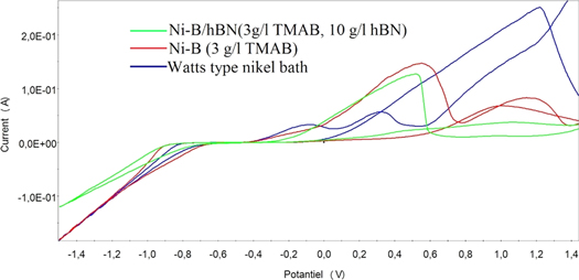
Figure 1. CV graphs of Ni–B allloy, pure nickel and Ni–B/hBN coatings (Scanning speed 10 mV s−1, between voltage −1.5 V to 1.5 V, additives sodium dodecyl sulfate, saccharine and 30 min ultrasonic agitation for composite coating bath) [51–53].
Download figure:
Standard image High-resolution imageCo-deposition of reinforcing particles with a metal can be expressed by the model of Guglielmi. According to this theory, the surface of the reinforcing particles in the electrolyte is surrounded by electrochemically reducible metal ions, in other words, metal ions are adsorbed onto the particles. Later, with the influence of the electric current, the particles along with the ionic clouds are attracted toward the cathode (the substrate to be coated). The second phase reinforcement particles adsorb loosely to the cathode surface first. Then, when the metal ions discharge their electrical load, the particles are trapped in growing layers of the metal deposited on the surface and thus co-deposited in the main structure. Step by step the deposition period continues in this manner [63].
2.2. Content analysis of these composite coatings
Energy dispersive x-ray spectrometry (EDS) method is generally used to the content analysis of such coatings. In table 2, the element content values of Ni–B matrix composite coatings are presented comparatively. The maximum values obtained in terms of reinforcing particles are given as well. In some publications, some values related to content have not been given clearly, but evidence has been presented that the reinforcement particles are successfully deposited with the Ni–B alloy matrix through various methods of analysis. In addition, the resulting particle content values were given as bar graphs in figure 2 to further illustrate the event.
Table 2. Content analysis of Ni–B alloy matrix composite coatings.
| Composite coating | Ni (wt%) | B (wt%) | Reinforcement particle contents (wt%) | References |
|---|---|---|---|---|
| Ni–B/CeO2 | 88.66 | 6.54 | 4.79 | [6] |
| Ni–B/TiO2 | 98.58 | — | 1.74 (Ti) | [38, 39] |
| Ni–B/Al2O3 | 91.87 | 6.51 | 1.61 | [40] |
| Ni–B/Si3N4 | — | — | 8 | [41–43] |
| Ni–B/ZrO2 | 90.81 | 1.95 | 7.23 | [44] |
| Ni–B/B | — | 34.3 | — | [45] |
| Ni–B/ ZrO2–Al2O3 | — | 7.7 | 1.2 ve 2.7 | [46] |
| Ni–B/SiC | — | — | ∼12 | [47] |
| Ni–B/Y2O3 | — | — | — | [48] |
| Ni–B/Diamond | — | — | ∼23 | [49] |
| Ni–B/Fe2O3 | 57.46 | 2.65 | 39.89 | [50] |
| Ni–B/hBN | 87.2 | 11.15 | 2.72 (Nitrogen) | [51–53] |
| Ni–B/SiO2 | — | — | — | [54] |
| Ni–B/ Al2O3 | — | ∼15 | ∼5 | [34, 55] |
| Ni–B/AlN | 78.53 | 13.63 | 7.84 | [56] |
| Ni–B/V2O5–ZrO2 | 73.60 | 5.90 | 5.54 ve 14.9 | [57] |
| Ni–B/Diamond | — | 5.5 | — | [58, 59] |
| Ni–B/SiC | — | — | 12 | [35–37] |
| Ni–B/Tl2O3 | 76.18 | 13.89 | 9.93 | [60] |
| Ni–B/La2O3 | 82.48 | 14.08 | 3.44 | [61] |
| Ni–B/SiC | — | — | 11 | [62] |
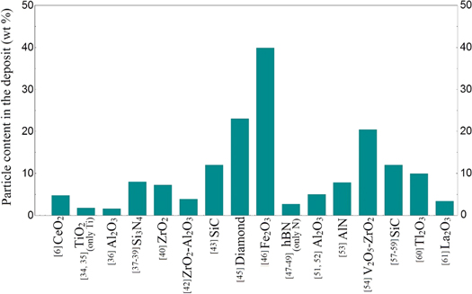
Figure 2. Particle content (wt%) in the composite coatings (In TiO2 and hBN particle studies only the content information of one element was given).
Download figure:
Standard image High-resolution imageOgihara et al [47] reported that in the Ni–B/SiC composite coating studies, the content of co-deposited particles in the coating increased continuously with the increase the particle bath concentration. The authors also examined the effect of current density on the SiC content in the coating and stated that the content of the particles gradually decreased at higher values than the current density of 10 mA cm−2. Krishnaveni et al [41] declared that the increase in the Si3N4 bath concentration firstly increased the amount of particles in the coating, and then decreased the amount of the particles after a certain concentration value. This is an indication of how the properties of the materials forming the composite coating affect the production process. In some cases, the increase in particle bath concentration increases the likelihood of more particles around the cathode, but for some materials the higher bath concentration causes agglomeration and a reduction in the particle content of the coating occurs, even with continuous mixing [64]. The authors also noticed that the Si3N4 particles content in the composite coating rapidly decreased after the current density value of 10 mA cm−2.
3. Bath production parameters of composite coatings with Ni–B alloy matrix
In electrodeposition systems, the production parameters have various effects on the properties of the coatings. The electrochemical production parameters of the Ni–B alloy matrix composite coatings were presented comparatively in table 3. One of the most important production parameters for electrochemical coating production is the current density and it affects the characteristics of the coating very highly. However, in studies on composite coatings wits Ni–B matrix, it was observed that the current density effect on the coating was insufficiently investigated. Except for few studies, examining the effect of current density, it was seen that a current density of 50 mA per cm2 was used and direct current was used without pulse in all papers. Li et al [34] analysed the current density effect on the composite coating in Al2O3 particle-reinforced Ni–B alloy coatings. The authors reported that the amount of particles in the coating decreased at higher current densities than 10 mA cm−2. According to the authors, this is due to the fact that metal ions at higher current density values move faster than the second phase particles towards the cathode. The temperature of the bath during deposition is also an important factor. One of the most important benefits of electrochemical coating is that this method does not need very high temperatures during electroplating production. As can be seen in table 3, bath temperature values in the production of Ni–B matrix composite coatings vary between 43–53 ° C. However, in Ni–B based coating baths, the pH values are generally set between 3.5 and 4.5, and chemicals such as HCl, NaOH, H2SO4, and NiCO3 are used to adjust the pH of the electrolyte. Ogihara et al [8] studied the effect of pH value on hardness and boron content of Ni–B alloy coatings and reported that optimum pH value for hardness was about 3.5. The authors also stated that it was possible to increase the boron content in the coating by increasing the pH value due to TMAB and DMAB dissolve in acidic solutions. Coating duration is one of the two factors that directly affect the coating thickness. As the coating time increases, the coating thickness increases. It is understood that the coating time was generally limited to 30 min in Ni–B based composite coatings. As shown in table 3, a fixed period of time was usually used. In Ni–B/Si3N4 [41–43] and Ni–B/SiC [35–37] composite coatings, the effects of coating duration were investigated and deposition process was carried out at different durations.
Table 3. Bath production parameters of Ni–B alloy matrix composite coatings.
| Composite coating | Current density (mA cm−2) | Temperature (°C) | pH | Coating duration (min) | Agitation speed (rpm) | Ultrasonic mixing before deposition (min) | References |
|---|---|---|---|---|---|---|---|
| Ni–B/CeO2 | 50 | 43 ± | 4 | 30 | 300 | — | [6] |
| Ni–B/TiO2 | 50 | 45 ± 1 | 3.5 ± 0.2 | 30 | 400 | — | [38, 39] |
| Ni–B/Al2O3 | 50 | 43 ± 1 | 4 | 60 | 500 | — | [40] |
| Ni–B/Si3N4 | 4–40 | 45 ± 1 | 3.5 | 40–180 | 600 | — | [41–43] |
| Ni–B/ZrO2 | 50 | 43 ± 1 | 4 | 60 | 500 | — | [44] |
| Ni–B/B | 10 | 45 | — | — | — | — | [45] |
| Ni–B/ ZrO2-Al2O3 | 50 | 53 ± 1 | 4 ± 0.1 | 30 | 500 | — | [46] |
| Ni–B/SiC | 5–40 | 50 | 3.5 | — | — | — | [47] |
| Ni–B/Y2O3 | 50 | 45 ± 1 | 4 ± 0.2 | 30 | 500 | — | [48] |
| Ni–B/Diamond | 3.5–100 | 50 | 3.5 | — | — | — | [49] |
| Ni–B/Fe2O3 | 50 | 53 ± 2 | 4.0–4.5 | 30 | 600 | — | [50] |
| Ni–B/hBN | 50 | 43 ± 1 | 4 | 60 | 200–600 | 30 | [51–53] |
| Ni–B/SiO2 | 50 | 45 ± 2 | 4 ± 0.2 | 60 | 500 | — | [54] |
| Ni–B/ Al2O3 | 5–70 | 50 | 3.5 | 30 | 300–400 | — | [34, 55] |
| Ni–B/AlN | 50 | 55 ± 2 | 4.0–4.5 | 30 | 600 | — | [56] |
| Ni–B/V2O5-ZrO2 | 50 | 55 ± 2 | 4.0–4.5 | 30 | 600 | — | [57] |
| Ni–B/Diamond | 1–3 | 50 | 3.5 | 60 | — | — | [58, 59] |
| Ni–B/SiC | 5–70 | 40–45 | 3.5 ± 0.1 | 15–90 | 450 ± 50 | — | [35–37] |
| Ni–B/Tl2O3 | 50 | 55 ± 1 | 4 ± 0.1 | 30 | 600 | — | [60] |
| Ni–B/La2O3 | — | Room temp. | 6 | — | — | 60 | [61] |
| Ni–B/SiC | 50 | 50 ± 2 | 3.5 ± 0.5 | 60 | 400 | 20 | [62] |
The mixing of the coating bath before or during deposition is of great importance in terms of ensuring a homogeneous distribution of the reinforcing particles in the electrolyte. Before deposition, the electrolyte is mixed with magnetic or ultrasonic shakers for a certain period of time and immediately the coating process can be started. During deposition, however, mixing process is usually carried out by means of magnetic stirrers. In table 2, for Ni–B alloys it was generally observed that the mixing process was performed between at 300–600 rpm during deposition. It is understood that ultrasonic mixing process before deposition in Ni–B alloy coating related works is not preferred. In many studies about electrochemical composite coating in the literature, ultrasonic mixing prior to deposition seems to be widely used. This process seriously affects the structure of the composite coating. Unal and Karahan [53] studied the effects of ultrasonic mixing before deposition in Ni–B/hBN composite coatings and reported that this process significantly improved the particles uniform distribution in the coating and the corrosion behavior of the coating.
3.1. Substrate (cathode) and anode materials used in Ni–B alloy composite coatings production
In composite coatings with Ni–B alloy matrix, it is seen that mostly low carbon steel is used as substrate material. Apart from steel, other used substrate material is copper but it is understood that it is less preferred than steel. The anode material used in the production of such coatings is usually a pure nickel plate. In addition to the nickel plate, graphite plate was used only for Si3N4 reinforced composite coating and platinum wire was used for hBN reinforced composite coating. When the studies about the Ni–B alloy matrix composite coatings were examined, it was seen that too much detail was not given about the position of cathode and anode materials in the bath. In general, it was reported that cathode and anode materials were placed vertically in the bath and parallel to each other, and the distance between them was reported to be about ∼20–25 mm. In most publications, cathode and anode placement positions have never been mentioned. In the electrodeposition process, the cathode and anode positions can significantly affect the coating properties. In previous studies, it was observed that this issue has never been discussed. Unlike other studies, Li et al [55] Ni–B/Al2O3 stated that they placed the cathode and anode horizontally in the composite coating bath and that the cathode was located at the lower part of the anode. The authors reported that placing this way would increase the content of the deposited particles and provide more uniform deposit.
4. Properties of Ni–B alloy matrix composite coatings
Hardness, crystal structure, morphology, corrosion resistance and tribological properties are affected when Ni–B alloy is reinforced with second phase inert particles. This effect may show a change according to size, quantity and type of the reinforcement particle, and electrochemical production parameters.
4.1. Crystal structure
The average crystal grain size of pure nickel coatings produced with electrodeposition method is between about 30–50 nm [7, 12, 18, 51]. With the addition of boron source (TMAB or DMAB) to the electrolyte, the incorporation of boron atoms to the structure seriously affects the crystallization and reduces the crystal grain size (about 8–12 nm) [7, 51]. Bekish et al [7] reported that electrodeposited Ni–B alloys had a nanocrystalline structure at boron contents below 8%, amorphous and nanocrystalline structure at boron contents of between 8%–20%, and x-ray amorphous structure at boron contents above 20%. The authors also stated that electrodeposited Ni–B alloy coatings were a mixed substituted-interstitial type solid solution of boron in the nickel face centered cubic lattice structure, and that this might be an indication that the boron was co-deposited as elementary form.
In XRD patterns of pure nickel electrodeposit, (200) diffraction peak is main peak (most intense) and beside this, intensity of (111) diffraction peak is considerably higher than the other nickel specific peaks. In the XRD patterns of the Ni–B alloy coatings obtained by the addition of boron source to the bath, only (111) diffraction peak were observed and the relative intensity of this diffraction peak also decreased and expanded considerably (figure 3). Addition of reinforcing second phase particles to the Ni–B alloy main structure influences the crystal structure and generally causes to become visible again the nickel-specific peaks. But some reinforcement particles may have different effects on crystal structure. In figure 3, XRD patterns of pure nickel, Ni–B and Ni–B/hBN coatings are given comparatively.

Figure 3. Comparison of x-ray diffraction patterns of Ni–B/hBN, pure nickel and Ni–B coatings (Current density 50 mA cm−2, pH 4, temperature 43 ± 1 °C, bath additives sodium dodecyl sulfate, saccharine and 30 min ultrasonic agitation before deposition for composite coating, deposition time 60 min) [51–53].
Download figure:
Standard image High-resolution imageZhang and Li [35] revealed that with increasing current density in Ni–B/SiC composite coatings, the crystal structure changed from amorphous into crystalline and grain size increased. According to the authors, high current density in Ni–B/SiC composite coatings promotes crystallization. Krishnaveni et al [41] noticed that as a result of supporting Ni–B alloy with Si3N4 particles, the Ni (200) diffraction peak became visible with increasing intensity and the Ni (111) diffraction peak broadened. Zhang et al [61] reported that the electrodeposited Ni–B alloy coatings had the amorphous/nanocrystalline structure and that the addition of La2O3 particles to the structure inhibited the growth of the (111) lattice plane.
4.2. Surface and cross-section morphology
Supporting Ni–B alloys with a reinforcing phase has a very serious effect on the morphology in some cases, but in some cases this effect is very small. Morphology is influenced by parameters such as type of reinforcement phase, particle size, deposition current density. Particularly increase in particle size and deposition current density leads to obtain a more coarse surface. In figure 4, SEM images of pure nickel, Ni–B alloy and Ni–B/hBN composite coatings were given [51–53].
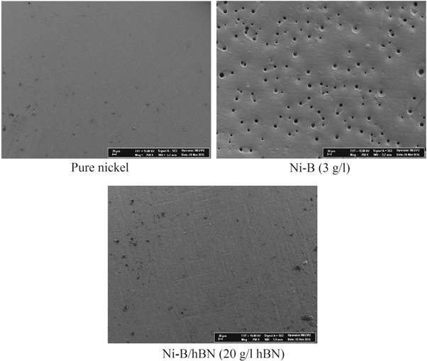
Figure 4. SEM images of pure nickel, Ni–B alloy and Ni–B/hBN composite coatings (Current density 50 mA cm−2, pH 4, temperature 43 ± 1 °C, bath additives sodium dodecyl sulfate, saccharine and 30 min ultrasonic agitation before deposition for composite coating, deposition time 60 min) [51–53].
Download figure:
Standard image High-resolution imageMirak and Akbari [65] studied the effects of boron content on the surface roughness of the Ni–B alloy. According to the authors, the minimum surface roughness value was obtained at 1.4% boron content (Ra: 0.09 μm). In higher boron contents than this value, the surface roughness was reported to increase (Ra: 0.24 μm for wt 4.2% B). The authors also demonstrated that the morphology of the pure nickel coating was faceted-like, while the surface morphology of the Ni–B alloy was nodular. The addition of reinforcement phase to the Ni–B alloy matrix can sometimes make the surface rougher and sometimes smoother. Waware et al [56] found ±3 nm for Ni–B alloy coating and ±10 nm for Ni–B/V2O5-ZrO2 composite coating in the measurements of average surface roughness with atomic force microscopy (AFM). In contrast, Shakoor et al [48] measured the average surface roughness values of 27.872 nm for Ni–B and 7.834 nm for Ni–B/Y2O3. Krishnaveni et al [40] reported that Ni–B alloy coatings had a fine-grained, well-crystallized and uniform structure, although they contain cracks due to internal stresses. The authors also reported that the Ni–B/Si3N4 composite coatings were crack-free and had a thin spherical structure in which the particles are homogeneously distributed throughout the matrix.
In composite coatings, the most reliable results to prove that reinforcing particles are deposited with the matrix are obtained from the cross-sectional images. In many cases it is possible to see, the particles embedded in the main structure from the cross-section can be seen. In the cross-section images given in figure 5, SiC and Al2O3 reinforcing particles in the Ni–B alloy matrix can be clearly seen. In nano-sized particles, sometimes particles can not be seen even in the cross-sectional images. In such cases, mapping analysis from the cross-sectional image can be used in order to determine whether the particles are present in the composite coating.

Figure 5. Cross-sectional images of composite films a) Ni–B/SiC (particle size and bath concentration 0.27 μm and 5 g l−1, current density 1 A dm−2). Reprinted from [47], Copyright (2014), with permission from Elsevier. b) Ni–B/Al2O3 (nano particle size and bath concentration of particle 15 g l−1). Reprinted from [55], Copyright (2018), with permission from Elsevier.
Download figure:
Standard image High-resolution image4.3. Hardness
Electrodeposited Ni–B alloy is a very hard material as compared to pure Ni deposition. The electrodeposited pure nickel hardness value is affected by the production parameters and additives added to the bath, and is reported to be in the range of 200 to 300 Hv in general. For electrodeposited Ni–B alloy, hardness values are obtained in the range of 700–800 Hv in its as deposited state. Sheu et al [30] examined the strengthening mechanism for electrodeposited Ni–B alloys and stated that the hardness increase was due to solid solution strengthening and fine grain strengthening. However, as a result of the heat treatment, it is seen that due to the Ni3B and Ni2B phases formation, the hardness increases considerably and reaches to the values of 1200–1300 Hv. This hardness value can vary slightly with the amount of boron in the alloy [8]. Ogihara et al [8] expressed that the increase in the TMAB content in the bath had not influence on the hardness after a certain level, and when DMAB was used, a maximum hardness value of about 900 Hv was obtained. From the literature studies, it was seen that the hardness values of the electrodeposited Ni–B alloys were increased due to the reinforcement with the inert particles. The hardness value of these coatings could be influenced from the quantity of particles added to the electrolyte, the current density of deposition and the particle type and size. Table 4 gives the maximum hardness and elastic modulus values obtained in the literature. Also, figure 6 shown the hardness values of the composite coatings. In addition, the hardness of Ni–B alloy composite coatings increases with the heat treatment. However, table 4 presents the hardness values of the non-heat treated coatings. From table 4, it was seen that the composite coating reinforced with diamond particles had the highest hardness value. It was reported that hardness value of Ni–B/diamond composite coating reached 3000 Hv with heat treatment [49]. Ogihara et al [48] demonstrated that in the production of Ni–B/SiC composite coatings, the hardness increased with increasing particle content and that they achieved a maximum hardness of ∼850 Hv. In the same study, the authors also investigated the heat treatment effect on the hardness of the composite coating and reported that a maximum hardness value of ∼1500 Hv was achieved. In another study, Ogihara et al [49] showed that the increase in current density in the production of Ni–B/diamond composite coatings caused a significant reduction in the hardness value.
Table 4. Hardness values of Ni–B alloy matrix composite coatings.
| Ni–B alloy coating | Composite coating | ||||
|---|---|---|---|---|---|
| Composite coating | Hardness | Elastic module | Hardness | Elastic module | References |
| Ni–B/CeO2 | 11 GPa | 120 GPa | 37 GPa | 180 GPa | [6] |
| Ni–B/TiO2 | 677 Hv | — | 1061 Hv | — | [38, 39] |
| Ni–B/Al2O3 | 11 GPa | 120 GPa | 14 GPa | 140 GPa | [40] |
| Ni–B/Si3N4 | 609 Hv | — | 640 Hv | — | [41–43] |
| Ni–B/ZrO2 | — | — | — | — | [44] |
| Ni–B/B | 760 Hv | — | 810 Hv | — | [45] |
| Ni–B/ZrO2–Al2O3 | 8.8 GPa | 98 GPa | 15 GPa | 116 GPa | [46] |
| Ni–B/SiC | 720 Hv | — | 850 Hv | — | [47] |
| Ni–B/Y2O3 | 9 GPa | 97.6 GPa | 16 GPa | 288 GPa | [48] |
| Ni–B/diamond | 800 Hv | — | 2000 Hv | — | [49] |
| Ni–B/Fe2O3 | 12.5 GPa | 120 GPa | 19 GPa | 190 GPa | [50] |
| Ni–B/hBN | 736 Hv | — | 680 Hv | — | [51–53] |
| Ni–B/SiO2 | — | — | — | — | [54] |
| Ni–B/ Al2O3 | — | — | 870 Hv | — | [34, 55] |
| Ni–B/AlN | 13 GPa | 125 GPa | 19 GPa | 190 GPa | [56] |
| Ni–B/V2O5–ZrO2 | 13 GPa | 125 GPa | 36 GPa | 210 GPa | [57] |
| Ni–B/Diamond | 800 Hk | — | 900 Hk | — | [58, 59] |
| Ni–B/SiC | 700 Hv | — | 900 Hv | — | [35–37] |
| Ni–B/Tl2O3 | 12.5 GPa | 120 GPa | 22.5 GPa | 195 GPa | [60] |

Figure 6. Hardness values of Ni–B alloy matrix composite coating (a) given as Hv, (b) given as GPa.
Download figure:
Standard image High-resolution imageThe increase in hardness as a result of the addition of particles to the Ni–B alloy structure was expressed via the Orowan dispersion hardening mechanism in the literature [40]. The presence of inert particles in the main structure blocks the dislocation movements and the dislocation pinning effect caused the strengthening effect of the dispersed particles. The critical condition for a dislocation passing by particles in motion orbits is that they twist themselves as a semicircle between particles. Then the dislocation moves forward and leaves the dislocation node behind. Because of the codeposition of inert nano or micro particles with the main structure, dislocation pinging effect may occur and thereby increasing the strength and hardness [40].
4.4. Corrosion behavior
Along with the addition of boron atoms to the pure nickel coating, corrosion performance may be reduced, although the wear resistance and hardness of the alloy coating may improve. Bekish et al [7] reported that the corrosion resistance of Ni–B alloys was higher in low boron content, but the corrosion resistance decreased as boron content increased. The authors stated that as the boron content increased in the Ni–B alloy coating, cracks and fractures increased in the coating, leading to a decrease in corrosion resistance in this case. Lopez et al [18] also similarly stated that corrosion resistance was low due to cracks and that the crack problem must be solved in order to increase the resistance of corrosion. Orinakova et al [17] revealed that the corrosion resistance of Ni–B alloy coatings is worse than that of pure nickel coatings. Chang et al [19] point out that Ni–B alloy coatings they produced without cracks have better corrosion resistance than pure nickel and that the main factor in corrosion resistance is grain size. According to the authors, there was a decrease in the corrosion resistance with decreasing grain size. Krishnaveni et al [26] produced Ni–B alloy coatings by modifying Watts bath and reported that the corrosion resistance of these alloy coatings was better than pure nickel. However, the addition of inert reinforcement particles to the Ni–B alloy made the corrosion performance better than pure nickel. In literature, improvement of corrosion resistance in all second-phase particle reinforcements examined in terms of corrosion performance was reported. In table 5, corrosion current and corrosion potential values of Ni–B alloy and its composites obtained by Tafel Extrapolation method were given comparatively. The corrosion potential of Ni–B alloy films was measured around −0.4 and −0.5 V and the corrosion current was between 12 and 24 μA/cm2 as seen from table 5. In the literature, it is stated that the materials which are on the more positive side in the corrosion potential comparison are more noble and therefore more resistant to corrosion. In Ni–B alloy composite films, the value on most positive side in terms of corrosion potential was obtained with diamond [58] particle reinforcement and reported as −0.18 V. The best performance in terms of corrosion current, i.e. the lowest value, was obtained with the hBN [51–53] particles reinforcement and reported to be measured as 2.44 μA cm−2. In figures 7 and 8, the corrosion current and corrosion potential values of the composite coatings are presented. Composite coatings in the best and worst case from the point of corrosion performance are clearly visible in these bar graphs. In table 5, the differences in the corrosion performance values of Ni–B alloy coatings can be attributed to changes in production parameters. Various opinions were given in the literature about the development of corrosion resistance as a result of reinforcement of matrix material with ceramic particles. The various cracks, cavities and micron-sized holes in the coating are filled by the reinforcing particles acting as a physical barrier in terms of corrosion and this cause to an improvement in corrosion resistance [66]. Another observation on this point is that in the deposition process, the reinforcing particles are well dispersed at growing grain boundaries reduce defects in the deposit and make the coating more compact and less permeable, resulting in improved corrosion resistance [20]. The heat treatment effects on corrosion resistance of Si3N4 [41–43] reinforced Ni–B alloy composite coating were also investigated and it was pointed out that heat treatment deteriorated corrosion performance. Mehr et al [67] investigated the effect of nano and micro particle sizes on coating properties in Ni–B/SiC composite coatings and reported that nano-sized particles were more resistant to corrosion.
Table 5. Corrosion current and corrosion potential values of Ni–B alloy and its composites.
| Ni–B/X composite coating | Ni–B corrosion potential V | Ni–B corrosion current μA/cm2 | Ni–B/X composite coating corrosion potential V | Ni–B/X composite coating corrosion current μA cm−2 | References |
|---|---|---|---|---|---|
| Ni–B/CeO2 | −0.33 | — | −0.32 | — | [6] |
| Ni–B/TiO2 | −0.38 | 13.55 | −0.36 | 5.53 | [38, 39] |
| Ni–B/Al2O3 | −0.43 | — | −0.41 | — | [40] |
| Ni–B/Si3N4 | −0.58 | 12.31 | −0.56 | 10.92 | [41–43] |
| Ni–B/ZrO2 | −0.42 | — | −0.26 | — | [44] |
| Ni–B/B | — | — | — | — | [45] |
| Ni–B/ZrO2–Al2O3 | −0.48 | 24 | −0.52 | 9.7 | [46] |
| Ni–B/SiC | — | — | — | — | [47] |
| Ni–B/Y2O3 | −0.6 | 19.3 | −0.5 | 6.9 | [48] |
| Ni–B/Diamond | — | — | — | — | [49] |
| Ni–B/Fe2O3 | −0.5 | 16.8 | −0.48 | 7.15 | [50] |
| Ni–B/hBN | −0.65 | 17.41 | −0.49 | 2.44 | [51–53] |
| Ni–B/SiO2 | −0.42 | 18.2 | −0.24 | 15.5 | [54] |
| Ni–B/ Al2O3 | — | — | −0.47 | — | [34, 55] |
| Ni–B/AlN | −0.5 | 16.8 | −0.48 | 6.23 | [56] |
| Ni–B/V2O5–ZrO2 | −0.5 | 16.8 | −0.4 | 5.97 | [57] |
| Ni–B/Diamond | −0.16 | — | −0.18 | — | [58, 59] |
| Ni–B/SiC | — | — | −0.45 | — | [35–37] |
| Ni–B/Tl2O3 | −0.504 | 16.8 | −0.299 | 10.18 | [60] |

Figure 7. Corrosion current values of Ni–B alloy composite coatings.
Download figure:
Standard image High-resolution image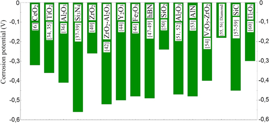
Figure 8. Corrosion potential values of Ni–B alloy composite coatings.
Download figure:
Standard image High-resolution image
4.5. Tribological properties
It was observed that the addition of boron to pure nickel improves the wear resistance, taking into account the electrodeposited Ni–B alloys in literature. Bekish et al [7] noticed that when the boron content in the Ni–B alloys was increased up to 8%, the wear performance also increased, but in the higher boron contents the wear resistance decreased. Lee et al [9] showed that wear performance of Ni–B alloy coatings reduced in high boron contents due to brittle fracture and high friction coefficient. Liang et al [16] examined that Ni–B alloy coatings without heat treatment had better wear resistance than Cr coating, although they have lower hardness than Cr coatings. In addition, the authors applied heat treatment to the Ni–B alloy at different temperatures and indicated that the best wear resistance was obtained from a 300 °C heat treated sample.
One of the most important reasons for reinforcing a matrix material with ceramic particles is undoubtedly the improvement of wear performance. Zhang and Li [35] reported that the friction coefficient of the composite coating increased from 0.38 to 0.43 with increasing TMAB electrolyte concentration in their studies about Ni–B/SiC composite coatings. The authors also stated that the wear resistance of Ni–B/SiC composite coating was better than Ni-SiC and Ni–B coatings. In another study used SiC particles as reinforcement, Ahmadiyeh et al [62] reported that the lowest friction coefficient (0.57) and weight loss (0.98 mg cm−2) values were measured from the sample produced in a bath of 12 g l−1 SiC compared to other samples. Li et al [54] revealed that the particle reinforcement the Ni–B alloy with Al2O3 was an enhancing effect on wear resistance. Wang et al [38] reported that the friction coefficient of the Ni–B alloy decreased from ∼0.4 to ∼0.315 with TiO2 reinforcement and besides that its wear resistance increased. Ogihara et al [47] showed a weight loss of 1.3 mg cm−2 in the Ni–B alloy wear test, while they reported a weight loss of 0.67 mg cm−2 in the Ni–B/SiC composite coating wear test. In addition, the authors noted that the weight loss of the composite coating decreased to 0.39 mg cm−2 as a result of heat treatment. Ogihara et al [48] stated that the wear resistance of Ni–B/diamond composite coatings reinforced with diamond particles showed a significant improvement compared to Ni–B alloy coatings. The authors also indicated that the the composite coating wear resistance was not affected by surface roughness and hardness. Krishnaveni et al [42] noticed that Ni–B/Si3N4 composite coatings had better wear resistance than Ni–B alloy coatings and that the wear mechanisms of the coatings were similar.
5. Possible applications of Ni–B alloy composite coatings, future works, recommendations and criticisms
While Ni–B alloy coatings are not as popular as pure nickel and Ni–P coatings, they can easily find application areas in many industries thanks to their promising properties. Ni–B alloy coatings have better wear resistance than hard chromium and have higher hardness than tool steel [68]. When this alloy coating is reinforced with secondary phase particles it will perform better against the difficulties encountered in the application phase and can be used much more successfully where Ni–B alloy coatings can be used when produced with optimum parameters. For example, hBN, carbon, MoS2, Al2O3 and SiC particles can be used in applications where abrasion resistance and low friction coefficient are required. In addition, hBN, Al2O3, Si3N4 or TiO2 may be preferred in applications where corrosion resistance is desired. If high hardness is desired, composite Ni–B coatings reinforced with diamond, CeO2, ZrO2 or TiO2 particles can be applied to the material concerned. Instead of modifying the entire material, only changing the surface is both more practical and less costly. Ni–B alloy composite coatings are materials with advanced features and can be easily applied to many parts used in petroleum, nuclear, automotive, textile, electronic industries. For example, these coatings can be used in moving parts used in internal combustion engines where wear resistance and improvement lubrication are required [69]. In petroleum and chemical industry applications Ni–B alloy composite coatings may be preferred in terms of corrosion resistance. In nuclear reactors, due to the ability of the boron element to absorb neutrons, boron-containing reinforcement particles such as hBN, TiB2, B4C and bor element as alloy can be used [70]. In addition, nanocrystalline Ni–B alloy composite coatings may be recommended for intergranular stress corrosion cracking and some local degradation in heat exchangers used in nuclear industry [71, 72]. Particularly in textile machines, parts in contact with the fabric are expected to have improved tribological properties and Ni–B alloy composite coatings can be applied to textile machine parts. This coating will prolong both the life of the parts and reduce the possibility of damage to the fabric of the part [73]. Kwon et al [12] stated that Ni–B alloys could be used in micro-electromechanical systems (MEMS) manufacturing processes. When the particle type to be used with Ni–B coatings is selected, the production parameters must be carefully determined in order to obtain the most optimum coating. For commercial application of a Ni–B alloy composite coating, it should be taken into consideration that it is necessary to carry out sufficient research and development studies.
More studies are needed about Ni–B alloy matrix composite coatings and the advantages and weaknesses of these coatings should be further investigated using more variety of analysis methods. There are still many issues that need to be clarified even in studies related to these coatings in the literature. For example, the advantages and disadvantages of TMAB and DMAB used as boron sources compared to each other have not been studied experimentally. In addition, both content of the boron and the particle in composite film decrease with the increase of current density, but in this case the amount of metal deposited is reduced. In order to obtain more coating thickness in a short time, it is necessary to work at higher current densities. In Ni–B alloy coatings, more solutions can be explored to overcome the problem of low current density. There are also many second phase particle types (TiC, MoS2, TiN, SmO3, G2O3, B4C, WC, ZrC, etc) which are not used as reinforcing elements in these coatings. Experimental studies should be done with these particles and should be brought into literature. Moreover, studies can be carried out by mixing different types of second phase particles and the effects of this mixture on the coating properties can be examined (for example; TiC-TiN, SmO3-G2O3, B4C-hBN, WC-ZrC). The fact that the particle sizes are nano or micro size also seriously affects the coating structure and properties. For the same particle type, experimental studies of different sizes should be made and their properties should be compared. The positions of the cathode and anode materials in the plating bath and the distances between them can also seriously affect the coating properties. It was observed that there was no study on cathode and anode placement in Ni–B alloy coatings and the effects of this issue on coating properties were not investigated. Besides, mixing of the electrolyte is an important issue and further work is needed on this subject.
It has been observed that the studies on electrodeposited Ni–B alloy composite coatings remained at the level of samples and analyzes produced in the laboratory. Almost no studies have been conducted on possible engineering applications for these coatings. For example, universities and related sectors (automotive, electronics, textiles, chemistry, etc) can produce joint projects on such coatings, and thus coatings commercially usable can be obtained. By means of these studies, the area of usage of such coatings can be increased. Such coatings can be applied on friction surfaces in various machines and can be examined how they affect the efficiency and performance of the machine. In another aspect, studies can be carried out on how long these types of coatings extend the life of the machine parts to which they are applied.
6. Conclusion
Ni–B coatings can be successfully used in many industries and are a good alternative to hard chrome coatings. In this paper, electrodeposited Ni–B alloy matrix composite coatings were investigated in detail. Electrolyte components and electrochemical production parameters used in the production of these composite coatings, as well as content analysis, hardness and corrosion results of the produced coatings were presented in tabular form. In addition, content, hardness and corrosion results were given in a bar graph to make a better comparison. Studies on electrodeposited Ni–B alloys and its composites shown a rapid increase in recent years, but more research is needed to reveal unknown spots about these coatings. Considering the studies on these coatings, it was seen that the properties of pure nickel were improved due to alloying with boron element. However, as a result of the reinforcement of the Ni–B alloy with the ceramic particles, it was revealed that the properties of the coating reached higher levels. It was seen that TMAB or DMAB was added to the electrolyte as boron source in the production of the composite coatings with Ni–B matrix. It was observed that the amount of the particulate content in the composite coating after 10 mA cm−2 decreased in the studies examining the current density effect on the particle content. Particularly in such coatings, particle reinforcement was shown to significantly enhance the properties of abrasion resistance, hardness and corrosion. It was reported that the corrosion resistance of Ni–B alloy matrix composite coatings was improved in all reinforcing particle types studied in the literature. In addition, it was shown that in all other reinforcement types except hBN reinforcement, the hardness of the composite coating was higher than the Ni–B alloy coating. With the addition of boron to the pure nickel coating, the crystal structure exhibited almost amorphous properties, while the addition of reinforcing particles to the Ni–B alloy supported crystallization. Furthermore, the tribological properties of Ni–B matrix composite studies were also investigated in only a few reinforcing types and it was revealed that abrasion resistance improved.