

Abstract
SiC nanowire aerogel (SNA) with highly porous 3D nanowire architecture was synthesized by polymer pyrolysis chemical vapor deposition (PPCVD) process to deposit SiC nanowires in the pores of carbon foam, followed by high temperature oxidation of carbon foam. The microstructure of the prepared SNA was characterized by SEM, TEM and a large number of interweaving SiC nanowires with a diameter of 80–100 nm and a length of hundreds of micrometers form the highly porous 3D nanowire architecture of SNA. The prepared SNA possesses the performance combination of ultra-low density (30 ± 7 mg · cm−3), high-temperature oxidation resistance (750 °C), noncombustible and fire resistance property in the fire, excellent thermal insulating property (0.03 W · m−1 · ·k−1 at room temperature in He) and compressive strength of 0.11 MPa, which is applicable as high-temperature heat insulator, ceramic matrix composite, high temperature flue gas filter, fire-proofing material and catalyst carrier.
Export citation and abstract BibTeX RIS
1. Introduction
Ceramic aerogels are a kind of nanoscale mesoporous composites with low-density, large surface area, high porosity and low thermal conductivity which have great potential to be used in fields of thermal protection system, catalyst support, filter, electronic and optical applications [1–7]. Typically, ceramic aerogels are composed of ceramic oxide nanoparticles such as silica and alumina. However, products fabricated by these raw materials possess brittle nature of ceramic and volume shrinkage at high temperature, which have always limited its practical applications [8, 9]. For example, the thermal insulators used to protect spacecraft has to withstand the heat shock (>700 °C) due to the aerodynamic heating and compression shock [10, 11]. Catalytic gas combustion requires the catalyst to work at flame temperature, which demands the catalyst support with the properties of noncombustible and fire-resistance [12, 13]. Therefore, ceramic aerogels with low density, low thermal conductivity and high temperature resistance are particularly urgent.
Aerogels constructed by silicon carbon (SiC) with superior high temperature thermal and chemical stability than oxide ceramic aerogels were synthesized by sol-gel and carbothermal reduction, which provides promising perspectives to be used under harsh environments [14, 15]. But the current SiC aerogels still have disadvantages of brittleness and large density. At the same time, the SiC aerogels prepared by sol-gel and carbothermal reduction cannot completely maintain the initial network structure of the precursors. In recent years, several aerogels based on nanoscale one- and two-dimensional materials such as carbon nanotube [16, 17], carbon nanofiber [18], graphene [19, 20] with the properties of ultra-low density, excellent mechanical properties and low thermal conductivity have drawn many scientists' interests. Due to the highly porous elastic interconnected three-dimensional (3D) nanowire structure and strong but flexible building modules of the aerogels consisted of the one- and two-dimensional materials, they have superior properties than the traditional aerogels consisted of nanoparticles. SiC nanowire is a special one-dimensional structure ceramic with excellent elasticity, flexibility, high tensile strength and high Young's modulus [21]. In spired by above analysis, a novel SiC nanowire aerogel with porous 3D nanowire structure consisted of SiC nanowires is expected to achieve more novel applications.
Here, an efficient method is introduced to synthesis a novel SiC nanowire aerogel (SNA) with highly porous elastic interconnected three-dimensional (3D) nanowire network structure consisted of SiC nanowires. Carbon foam with highly porous skeleton structure, uniform pores and low oxidation temperature is often used as the templet and growth matrix of ultra-light reticulated ceramic foam [22]. Here, A large number of ultra-long SiC nanowires were prepared in the pores of carbon foam by applying polymer pyrolysis chemical vapor deposition (PPCVD). Then, carbon foam was burned off leaving pure SiC nanowires owing to the lower oxidation temperature of carbon foam than SiC nanowires. Thanks to the well-interconnected highly porous 3D nanowire structure consisted of SiC nanowires with superior mechanical property and high temperature oxidation resistance, the prepared SNA can maintain the same shape and size with the templet after the oxidation of carbon foam. Keeping in view of the observed outstanding related characteristics, the SNA is expected to be used as high-temperature heat insulator, ceramic matrix composite, high-temperature filter, fire-proofing material and catalyst carrier.
2. Experimental procedures
2.1. Preparation of SNA
The fabrication process of SNA is shown in figure 1, which can be divided into four basic steps. The first step is the pyrolysis of melamine foam (MF) with a density of 5–7 mg · cm−3 and a porosity of over 99% to prepare the carbon foam. In the first step, the MF was carbonized in a tube furnace at the temperature of 1000 °C for 1 h, and the whole process was protected under high purity argon. Then, in the second step, catalyst Ni was introduced into carbon foam in the form of Ni2+ to promote the growth of SiC nanowires. The prepared carbon foam was soaked into the catalyst solution containing Ni2+ (0.1 mol L−1) obtained from ethanol (AC, ≥99.7%) and Ni (NO3)2 · 6H2O (AC, ≥98%), so as to distributed Ni2+ evenly over the skeleton of carbon foam. After drying for 12 h at room temperature, the carbon foam loaded with Ni2+ was prepared, which will be used as the templet and growth substrate of SNA.
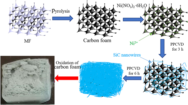
Figure 1. Detailed manufacturing processes of SNA.
Download figure:
Standard image High-resolution imageThe third step is the preparation of SiC nanowires in the pores of carbon foam via PPCVD. During the PPCVD, the off-gas from pyrolysis of Polycarbosilane (PCS) was used as SiC precursor. In order to slow down the release of the off-gas, PCS was adsorbed by activated carbon with a mass ratio of 1: 5. In the experiment, PCS (1 g) was dissolved in n-heptane (10 ml), then the prepared solution was mixed with activated carbon (5 g) which was grounded into uniform particles (20–40 mesh) in advance to form uniform suspension. After being dried in a box furnace, uniform composite powders were obtained. In the third step, the prepared composite powders were placed in a conventional ceramic boat, and the carbon foam loaded with Ni2+ in the second step was placed on the ceramic boat, then the ceramic boat and carbon foam were both pushed into a tube corundum furnace shown in figure 2. The furnace was heated up to 1300 °C with a heating rate of 5 °C · min−1 in a flowing of ultra-high pure argon with a slow rate (20 sccm) for 6 h. The fourth step is the removal of carbon foam, in which pure oxygen was placed into the furnace at a very low rate (20 sccm) at 500 °C for 2 h. Finally, when the furnace was cooled to room temperature naturally, the pure SNA was obtained.

Figure 2. Preparation equipment schematic of the SNA.
Download figure:
Standard image High-resolution image2.2. Materials characterization
The microstructure of the samples was studied under scanning electron microscope (SEM, FEI quanta 650). The elemental composition of SiC nanowires was studied by energy dispersive spectroscopy (EDS). The infrared absorption spectra of SiC nanowires was obtained by using a Nexus 670 Fourier Transforms infrared spectrometer (FT-IR) in the range of 350–4000 cm−1. X-ray diffraction (XRD) was carried out with a Rigaku D/max 2550 x-ray diffractometer (Rigaku, Japan). The compression tests of SNA and carbon foam were conducted by a universal testing machine (SNAS, Shenzhen, China CMT-8102). The size of samples for the compressive test was 10 × 10 × 10 mm3. The transmission electron microscope (TEM TF 20, Joel 2100 F) was used to observe the microscopic morphology of SiC nanowires. The thermal conductivity of the samples was test by a Laser thermal conductivity measuring instrument (TC 3200 China). The thermo gravimetric (TG) analysis was used to test the initial oxidation temperature of the samples. The densities of the samples were calculated by measuring geometries and mass of the samples.
3. Results and discussions
3.1. Appearance of the products
The photographs of white MF, black carbon foam and light blue SNA are shown in figure 3. As can be seen from figure 3(a), the white colored MF became black colored carbon foam after the carbonization. Then the black colored carbon foam turned to light blue colored SNA after deposition of SiC nanowires and oxidation of carbon foam due to the nature color of the SiC nanowires [23]. Furthermore, both the carbon foam and SNA retained the initial shape of the MF. In figure 3(b), an orchid can easily support a piece of SNA with the size of 30 × 20 × 10 mm3, which shows the ultra-low density of SNA. The ultra-low density of the prepared SNA was also proved by the results of the density measurement shown in table 1, which reveals the density of 30 ± 7 mg · cm−3 for SNA.

Figure 3. (a) Photographs of melamine foam (MF), carbon foam and SiC nanowire aerogel (SNA); (b) Digital photograph of a piece of SNA with the size of 30 × 20 × 10 mm3 standing on an orchid, showing the ultra-light performance of SNA.
Download figure:
Standard image High-resolution imageTable 1. Density measurement results of MF, carbon foam and SNA.
| MF | Carbon foam | SNA | |
|---|---|---|---|
| Density (mg · cm−3) | 6 ± 3 | 4 ± 2 | 30 ± 7 |
3.2. Microstructure characterization
The highly porous 3D nanowire architecture of SNA and its formation process were studied by SEM and TEM. Figures 4(a)–(d) display the evolution of the microstructure from carbon foam to SNA. Figure 4(a) is the SEM image of carbon foam indicating that the carbon foam is a kind of highly porous material with the pore sizes range of 80–100 μm. In this article, SiC nanowires were fabricated by PPCVD. It is well known that under the same experimental conditions, the number and length of SiC nanowires depend on the deposition time. In the initial 3 h, some SiC nanowires were prepared in the pores of carbon foam which is shown in figure 4(b), and the skeleton of carbon foam can be seen clearly. When the deposition time was extended to 6 h, the skeleton of carbon foam was completely covered by lots of interweaving SiC nanowires, which is hard to be distinguished. Meanwhile, a large number of ultra-long SiC nanowires have already formed a complex highly porous 3D nanowire network structure which was well preserved after the burning of carbon foam shown in figure 4(d). Figure 4(e) is the SEM image with higher magnification revealing that the SiC nanowires with excellent microscopic morphology have a diameter of 80–100 nm. The EDS result of SiC nanowires shown in figure 4(f) indicating that the prepared SiC nanowire is mainly composed of Si and C elements, and little amount of O origins from the oxidation of SiC nanowires is found due to the little O2 in the argon [24].
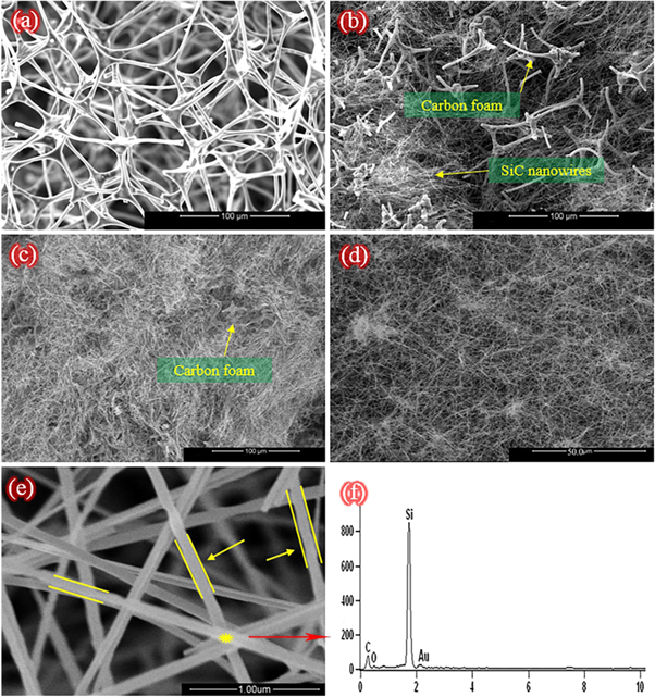
Figure 4. SEM images of the carbon foam and SNA; (a) Highly porous skeleton structure of carbon foam; (b) The growth of SiC nanowires in carbon foam for 3 h; (c) The growth of SiC nanowires in carbon foam for 6 h; (d) Highly porous 3D SiC nanowire architecture of SNA; (e) SEM image of SiC nanowires; (f) EDS result of the SiC nanowire in the yellow point.
Download figure:
Standard image High-resolution imageThe microstructure of SNA was further explored by TEM to find more details of the microstructure inside SNA. As can be seen from figures 5(a) and (c), many junctions named bundle and branch were formed among SiC nanowires. The first kind of junction is bundle which perhaps is produced by minimizing the system energy [25]. There is an amorphous oxide layer with the thickness of ∼10 nm on the surface of SiC nanowires (shown in figure 5(b)), which glues SiC nanowires tightly together. Another kind of junction named branch is shown in SEM image figure 5(c) and TEM image figure 5(d), which is probably caused by dendritic growth on a previous formed SiC nanowire under the supersaturation condition [26, 27]. Owing to the presence of a large number of bundles and branches among the nanowire architecture of SNA, the prepared SNA has a well-interconnected, highly porous 3D nanowire architecture. In addition, benefit from the perfect nanowire architecture of SNA, the prepared SNA has excellent performance in macroscopic physical properties such as mechanical property, thermal insulation and low density.
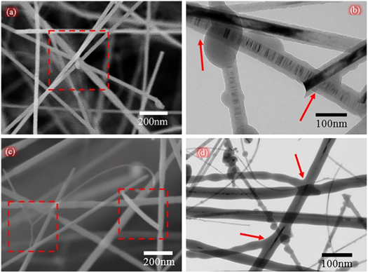
Figure 5. (a) SEM image of the SiC nanowire bundle; (b) TEM image of the SiC nanowire buddle; (c) SEM image of the SiC nanowire branch; (d) TEM image of the SiC nanowire branch.
Download figure:
Standard image High-resolution image3.3. Phases analysis of the SNA
XRD and FT-IR was carried out to understand the phase and composition of SNA. Figure 6(a) shows the XRD pattern of the obtained SNA. The 2θ values of the main peaks at 35.7°, 41.5°, 60.1°, 71.8° and 75.5° are in good agreement with the established values (JCPDS Card No. 73-1665), which can be attributed to the diffraction of the β-SiC (111), (200), (220), (311), and (222) planes respectively. Furthermore, there is a low-intensity peak at 2θ = 33.6° (marked with 'S.F'), which is usually ascribed to stacking faults in the β-SiC crystal [28]. Typically, the finer the diameter of the nanowire, the larger the stacking fault density in the SiC crystal, and the stronger the corresponding S.F peak. So, it can be considered that the diameter of the SiC nanowires constituting the SNA is small which is consistent with the measurement results of SEM images. The FT-IR spectra of SNA is shown in figure 6(b). The sharp peak at 789 cm−1 has a 21 cm−1 offset with respect to bulk Si-C bond characteristic peaks due to the modes of transverse optical (TO) phonons at the Γ point of the cubic SiC [29]. Besides, there is no more other peaks are found, which reveals that the SNA is consisted of pure SiC nanowires. After the above analysis, it can be concluded that the SNA is consisted of pure ß-SiC.

Figure 6. (a) The XRD pattern of the SNA; (b) The FT-IR transmittance spectrum of the SNA.
Download figure:
Standard image High-resolution image3.4. Growth mechanism of the SNA
There are some theories to explain the growth of SiC nanowires, such as vapor-liquid-solid (VLS) [30], vapor-solid (VS) [31] solid-liquid-solid [32]. Here, some droplets are found on the tips of SiC nanowires shown in figure 7(a). Meanwhile the result of EDS test exhibits that the droplets contain Ni elements besides Si and C which indicates that the growth of SiC nanowires is governed by VLS mechanism [31]. Because there were no SiC nanowires obtained when no PCS was employed, the Si and C elements of SiC nanowires must came from decomposition of PCS. During the pyrolysis of PCS, a lot of off-gas composed of cyclic silanes, silane fragments and H2 was released [33]. At high temperature, the Ni2+ was reduced to Ni atom by H2. As the reduction reaction proceeded, more and more Ni atoms were produced and aggregated into Ni nanodroplets dispersed in the pores of carbon foam. The cyclic silanes and silane fragments which are rich in Si and C elements were absorbed and dissolved by Ni nanodroplets, forming Ni–Si–C alloy droplets. To reduce the energy of alloy droplets, the SiC phase which is more stable was formed by the reaction of Si and C elements in droplets. When the content of SiC in Ni droplets was bigger than its solubility in Ni, the SiC crystal would be diffused and precipitated from the droplets forming SiC nuclei. The appearance of SiC nuclei formed a liquid-solid interface at the surface of droplet, which would promote the unidirectional growth of SiC nanowires. Due to the energy required to nucleate at the solid-liquid interface is less than the energy required to form a new nucleation site in the droplets, the nanowire will continue to form along the nucleation point as the silane fragments continuously dissolved. With the continuous dissolution of silane fragments and precipitation of SiC, the SiC nanowires become longer and longer [34]. As the number and length of SiC nanowires increased, the 3D highly porous nanowire structure of SNA was gradually formed.

Figure 7. (a) SEM image of the droplets in the tips of SiC nanowires; (b) EDS of the droplets in (a); (c) TG analysis of carbon foam and SNA; (d) TEM image of the SiC nanowires after oxidation at 900 °C.
Download figure:
Standard image High-resolution imageAfter the formation of the 3D highly porous SiC nanowires architecture, the carbon foam used as the growth matrix and template of SNA in the experiment should be removed to obtain pure SNA. Figure 7(c) is the curves of TG test for carbon foam and as-prepared SNA, indicating that the initial oxidation temperature of SNA is much higher than carbon foam. In figure 7(c), the reduction in weight of carbon foam began at 400 °C, while the change in mass of SNA stared at 750 °C. Owing to the reaction of C and O2, the carbon foam was completely burned off (equation (1)). And because of the passive oxidation (equation (2)) and active oxidation (equation (3)), there is a rising trend in the curve of SNA [35]. During the oxidation process of SiC nanowires, the well-coated SiO2 layer was produced shown in figure 7(d), which will protect SiC nanowires from further oxidation. Benefit from the outstanding high-temperature stability of SiC nanowires, the pure SNA with 3D highly porous SiC nanowires architecture could be obtained after the removal of carbon foam.


3.5. Properties analysis of SNA
The mechanical property is one of the important indexes for SNA in the practical applications. Figure 8 is the compressive stress-strain curve of SNA revealing that the maximum compressive stress of SNA is 0.11 MPa. In the compressive process, the initial stage is an elastic state, where the compressive stress increased steadily as the strain increased. When the elastic state was over, the compressive stress-strain curve does not drop suddenly, but slowly decreases, which is different from the compressive stress-strain curve of the traditional ceramic aerogels with brittle nature. As analyzed in the previous section, a large number of ultra-long SiC nanowires with excellent elastic, flexibility and high tensile strength make up the complex 3D porous nanowire network structure of SNA. And accompanied by the presence of many junctions (bundles figure 5(a) and branches figure 5(c)), makes the fracture process of SNA a kind of ductile fracture process which demonstrates that the prepared SNA is a kind of flexible material. As a comparison, the compressive stress-strain curve of carbon foam is also listed in figure 8, showing the maximum compressive stress of 0.01 MPa which is much smaller than the value of SNA. The superior mechanical property of SNA demonstrates that the highly porous 3D nanowire architecture composed of SiC nanowires is better than the skeleton structure of carbon foam.
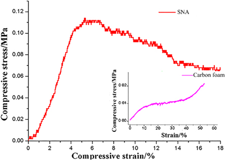
Figure 8. Stress-strain curves of prepared SNA and carbon foam.
Download figure:
Standard image High-resolution imageHigh temperature stability and excellent thermal insulation performance is two other attractive advantages for SNA. In the figure 9(a), a block of SNA is nonflammable in the flame of an alcohol lamp. After heating for more than 20 min in the fire, the SNA was well preserved, demonstrating the excellent fire resistance property of SNA. At the same time, combined with its highly porous 3D network, the SNA can be applied as high temperature flue gas filter and catalyst support. The thermal conductivity of SNA at different temperature is shown in figure 9(b). At room temperature, the thermal conductivity of SNA is 0.03 W · m−1 · k−1 which is comparable to the value of other heat insulators [36]. For comparison, the conductivity of carbon foam is also shown in figure 9(b), which is far bigger than SNA. Benefit from the Highly porous 3D nanowire network structure of SNA, it has superior thermal insulation performance than carbon foam with porous 3D skeleton structure. As the temperature increases, the thermal conductivity increases gradually due to the increasing thermal radiation of the gas estimated by the formula equation (4) [37]. It can be seen from the formula (4) that the effect of temperature on thermal conductivity is a relation of cubic which is consistent with the chart. In the formula (4), the бB is the Stefan-Boltzmann constant, ε is the emissivity, n is the refraction index and the d is the pore diameter. Because of the smaller pore diameter of the SNA than the carbon foam, the prepared SNA has superior high temperature thermal insulation property. The excellent thermal insulation property and high temperature resistance makes SNA an ideal high temperature thermal insulator.


Figure 9. (a) Fire-resistance performance of the SNA; (b) Thermal conductivity of SNA and carbon foam at different temperature.
Download figure:
Standard image High-resolution image
4. Conclusions
In summary, we put forward a simple method to fabricate a novel SiC nanowire aerogel with highly porous 3D nanowire network structure. The microstructure and properties of SNA were characterized, and the conclusion can be drawn as follows:
- (1)The SNA is fabricated via PPCVD to deposited SiC nanowires in the pores of carbon foam with highly porous skeleton structure. The carbon foam was used as the templet and growth matrix of SNA, which was burned off after the deposition of SiC nanowires, leaving pure SNA with well-interconnected, highly porous 3D nanowire architecture.
- (2)The highly porous 3D nanowire network structure of SNA is consisted of a large number of interweaving SiC nanowires with a diameter of 80–100 nm and a length of hundreds of micrometers. The presence of many bundles and branches among the SiC nanowires at atomic level improves the strength and flexibility of SNA.
- (3)The prepared SNA with property combination of low-density (30 ± 7 mg · cm−3), high-temperature oxidation resistance (750 °C), noncombustible and fire resistance, excellent thermal insulating performance (0.03 W · m−1 · k−1 at room temperature, 0.23 W · m−1 · k−1 at 900 °C in He) and compressive property of 0.11 MPa has great potential to be used as high-temperature heat insulator, ceramic matrix composite, high temperature flue gas filter, catalyst support and fire-proofing material. The process demonstrated in this article can easily achieve the industrial fabrication of samples with various shapes (in terms of size and volume).
Acknowledgments
The present work was supported by Policy Guidance project of Jiangsu Province (BY2016003-03), the key Research Program from the Ministry of Science and Technology of China and Science (2016YFC0304300), the NUAA Innovation Program for Graduate Education (kfjj20170615) and Priority Academic Program Development of Jiangsu Higher Education Institutions (PAPD).