
Abstract
Understanding the response of micro/nano-patterned graphene to mechanical forces is instrumental for applications such as advanced graphene origami and kirigami. Here, we analyze free-standing nanoribbons milled into single-layer graphene by focused ion beam processing. Using transmission electron microscopy, we show that the length L of the structures determines their morphology. Nanoribbons with L below 300 nm remain mainly flat, whereas longer ribbons exhibit uni-axial crumpling or spontaneous scrolling, a trend that is well reproduced by molecular dynamics simulations. We measure the strain of the ribbons as well as their crystallinity by recording nanometer-resolved convergent beam electron diffraction maps, and show that the beam tails of the focused ion beam cause significant amorphization of the structures adjacent to the cuts. The expansive or compressive strain in the structures remains below 4%. Our measurements provide experimental constraints for the stability of free-standing graphene structures with respect to their geometry, providing guidelines for future applications of patterned graphene.
Export citation and abstract BibTeX RIS

Original content from this work may be used under the terms of the Creative Commons Attribution 4.0 license. Any further distribution of this work must maintain attribution to the author(s) and the title of the work, journal citation and DOI.
1. Introduction
Transferring paper-work techniques such as origami and kirigami to graphene promises novel three-dimensional structures with a high potential for innovations [1–4]. These can be used to reduce the thermal conductivity [5], steer folding by dopants [6], and exploit tension for advanced kirigami patterns [7]. The prerequisites are the outstanding mechanical properties of graphene on the one hand and the influence of static ripples on the other hand, leading to a bending rigidity exceeding the expected value by three orders of magnitude [1]. To extend the application of kirigami, it is instrumental to control the mechanical properties of graphene down to the nanometer scale. While the in-plane stiffness can be manipulated by introducing defects [8], the thermal out-of-plane movement of ribbons is restricted by the available phonon spectrum [9, 10]. Also engineering the bending rigidity of single-layer graphene has remained challenging.
An alternative approach is to trigger changes in the morphology, such as scrolling, which effectively prevent bending of the material in the direction perpendicular to the scroll axis [11]. Scrolling of graphene has been studied extensively, both experimentally and theoretically [10, 12–24]. Among other methods [25], it can be induced by chemisorption [18, 19] and sonication [20, 21] as well as by wrapping membranes around molecules [22], nanodroplets [23], and carbon nanotubes [24].
Most studies have concentrated on freely moving ribbons, limiting the available spatial control; scrolling of doubly clamped nanoribbons has attracted less attention [26–29]. For these ribbons, scrolling is a length-dependent process, happens spontaneously, and is attributed to residual stress in the membrane [27, 28]. Due to the boundary condition, the energy gained by minimizing the surface has to balance the resulting strain. Based on this, a linear relation between the length of the ribbon and its narrowing was predicted [26]. While also crumpling of clamped ribbons has been reported [30, 31], the transition from a flat, to a crumpled, and a scrolled geometry has not been described yet.
Here we present a systematic study of the influence of the ribbons' aspect ratio on their morphology. Studying free-standing graphene nanoribbons written by Ga-ion-beam milling, we show that their morphology can be effectively manipulated by choosing the appropriate geometry. To assess the structure of the hexagons and thus the strain, the ribbons are studied down to the atomic level. This is achieved using scanning transmission electron microscopy and nanometer-scale convergent beam diffraction, supported by atomistic simulations. The results indicate that changes in the edge morphology lead to compressive strain in the ribbon, resulting in uni-axial crumpling.
We demonstrate how to incorporate carbon nanoscrolls with nanometer precision into macroscopic membranes. This is crucial for scrolls to be integrated into graphene-based devices or when patterning of free-standing graphene is required.
2. Results
2.1. Changes in morphology
In figure 1 we show the length-dependent changes in morphology for free-standing nanoribbons with an initial width wi of 150 nm. For small aspect ratios the nanoribbons remain flat. However, when we increase the length, the edge of the ribbon folds over and realizes a bilayer edge, as shown in figure 1(b). In this region we also observe significant uni-axial crumpling in the middle of the ribbons. Finally, for ribbons with a length above 1 µm, full scrolls are formed.
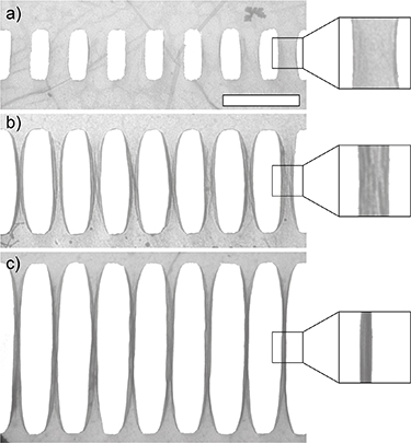
Figure 1. Length-dependent transition of a 150 nm wide nanoribbon from a flat to a scrolled geometry. While ribbons with a length of 330 nm remain flat (a), they show distinct crumpling and formation of bilayer edges at a length of 550 nm. Ribbons with a length of 1100 nm are completely scrolled (c). The scale bar corresponds to 500 nm.
Download figure:
Standard image High-resolution imageTo study this process systematically, we vary wi between 100 and 200 nm, and the length between 320 and 1100 nm. We use the minimum width wm of the ribbons as an indicator for structural changes. To assess wm , we vertically sum over a 30 nm high region centered at the smallest width of the ribbon and take the full width at half height of the resulting trace.
Figure 2 illustrates the impact of the ribbons' length L on the morphology for different values of wi
. For short ribbons, wm
decreases linearly with increasing L. This corresponds to the transition from straight over crumpled ribbons to complete scrolls, as shown in figure 1. The slope s is relatively independent of wi
, suggesting that the process depends only on L. For wi
= 100 nm and  nm, we observe a second linear regime, where the slope decreases from
  to
to 
 (figure 2(c)). In this region at least part of the ribbon is scrolled, realizing its minimum diameter. While further increase in L may lead to longer scrolls, it has no significant effect on wm
.
(figure 2(c)). In this region at least part of the ribbon is scrolled, realizing its minimum diameter. While further increase in L may lead to longer scrolls, it has no significant effect on wm
.

Figure 2. Minimum width wm
as a function of the length L for doubly-clamped nanoribbons. For each wi
the minimum width depends linearly on L: (a) slope  and intercept b = 204 ± 1 nm; (b)
  , b = 167 ± 2 nm; (c), (I)
  , b = 124 ± 2 nm; (c, II)
  , b = 48 ± 2 nm. (d) The respective slopes are relatively constant, suggesting that the reduction in width is independent of wi
. Squares correspond to folded ribbons and the star to a scroll (both MD-simulations). The circles show the results of the linear fits of panels (a)–(c). Here the value stated for wi
= 100 nm corresponds to region I in (c). The broken line at s =−0.2 illustrates the prediction for a perfect nanoribbon [26]. All shown standard errors have been multiplied by 5 to increase legibility.
, b = 48 ± 2 nm. (d) The respective slopes are relatively constant, suggesting that the reduction in width is independent of wi
. Squares correspond to folded ribbons and the star to a scroll (both MD-simulations). The circles show the results of the linear fits of panels (a)–(c). Here the value stated for wi
= 100 nm corresponds to region I in (c). The broken line at s =−0.2 illustrates the prediction for a perfect nanoribbon [26]. All shown standard errors have been multiplied by 5 to increase legibility.
Download figure:
Standard image High-resolution image2.2. Molecular dynamics simulations
In the experiments we observe a mixture of folding and scrolling. To investigate the dependence of the ribbons' morphology on their geometry, we perform molecular dynamics simulations (see section 5). We consider ribbons with wi
= 37 and 49 nm and induce the formation of folded bilayer edges as well as scrolls. The covalent carbon-carbon bonds are described with the Adaptive Intermolecular Reactive Empirical Bond Order (AIREBO) potential with an added Moire potential to describe the van der Waals interaction [32, 33]. In all cases wm
decreases linearly with L as soon as the van der Waals energy overcompensates the strain (supplementary information (available online at stacks.iop.org/2DM/8/025035/mmedia)). For folded ribbons, the slopes amount to 
 (wi
= 37 nm) and
(wi
= 37 nm) and  (wi
= 49 nm). Interestingly, scrolling minimizes wm
more effectively (
(wi
= 49 nm). Interestingly, scrolling minimizes wm
more effectively ( for wi
= 49 nm) than folding. Due to computational expenses, the simulations were only carried out for one orientation (and thus edge structure), and provide therefore no statistical variance. The stated error result from the uncertainty of the linear fit. In all cases, for structures with the same number of atoms, the folded ones were energetically favored over the scrolled ones.
for wi
= 49 nm) than folding. Due to computational expenses, the simulations were only carried out for one orientation (and thus edge structure), and provide therefore no statistical variance. The stated error result from the uncertainty of the linear fit. In all cases, for structures with the same number of atoms, the folded ones were energetically favored over the scrolled ones.
From figure 2(d) we can see that the experimental results are between the two limiting cases of a pure scroll and a pure fold. Furthermore, the value for a scroll (−154 ± 4) × 10−3 is in very good agreement with the values of the ribbons with an initial width of 100 and 200 nm.
2.3. Strain measurements
Changes in the morphology of the nanoribbons inevitably lead to strain, which sometimes is even the driving force for these changes. This is studied in an aberration-corrected scanning transmission electron microscope (Nion UltraSTEM 100) by recording convergent electron beam diffraction maps (see section 5). The method combines a series of diffraction patterns with a spatial resolution of 2 nm to reconstruct the forces acting on the ribbon. The strain is deduced from deformations of the lattice geometry as determined from the eccentricity and the orientation of an ellipse fitted to the diffraction pattern at each location. Results for a scroll are shown in figure 3, the analysis of a ribbon is shown in the supplementary information. The first row shows high-resolution annular dark field (HAADF) images, the other rows display the measured strain and the rotation of the fitted ellipse. The labels on the smaller images identify the sample position for each 4D map.
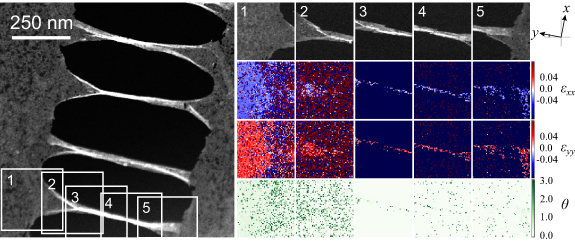
Figure 3. Overview HAADF STEM image and strain maps of a sample area containing scrolls. The smaller images correspond to 128 × 128 maps, where a HAADF intensity and convergent beam electron diffraction pattern has been recorded at each pixel. The positions of the maps are noted with the labels in the overview image. The second and the third row show the elongation along x and y (εxx and εyy ). The rotation of the ellipsoids in rad is shown in the bottom row.
Download figure:
Standard image High-resolution imageThe first clear observation is that the nanoribbons are largely amorphized by ion beam milling. This is illustrated in the leftmost strain map (1) in figure 3: reliable results over large regions are mostly obtained for the left half of the region although the membrane extends further to the right. For the ribbon itself the strain maps are very noisy—amorphized areas provide unreliable results. However, each map contains also areas where the strain can be measured, as seen from the locally less noisy data. The width of the amorphous region extends dozens of nanometers away from the cuts. In these areas the tail of the focused ion beam has reached a line dose sufficient to amorphize the material, but not high enough to cut [34]. In spite of the amorphization, the ribbons are stable over months as observed in molecular interference experiments [35], for which the impact of ion beam milling on the diffraction pattern has been discussed before [36, 37]. From maps recorded in the pristine region we see that the membrane is mainly elongated along the scroll axis (εyy ) and compressed perpendicular to it (εxx ). We point out, that the strain measurement for the two-dimensional graphene has an inherent uncertainty, since there is no guaranteed reference value from an aligned bulk crystal structure. From the strain maps we estimate the expansive and compressive strain to remain below 4%. However, these values should be treated with some caution.
Simulated strain maps for both scrolled and folded edges are shown in figure 4. Here the strain is computed from the average bond length. The spatial maps show a quarter of the final structure and are created by averaging the strain over an area of 1 × 1 nm2 and interpolating on the edges. For both geometries the strain remains below 1% and is mostly located at the folded/scrolled edge and the flat region close to the ribbon; the hexagons in the remaining ribbon are not elongated by much. On the contrary, the structures are compressed slightly in the middle of the ribbon. The results are thus in general agreement with the experimental data, indicating strain mainly along the scroll axis. Since the computational model uses average bond lengths, where as the experimental map is estimated from a converged beam electron diffraction pattern, the values are not directly comparable but rather provide complementary information.

Figure 4. Computational strain maps showing a quarter of the final structures. Both for the scrolled (a) and a folded geometry (b), the ribbon is mainly elongated at its edge (curved features) and the connection to the buffer region on the right. Independent of the edge morphology, the ribbons are slightly compressed in the middle. The maps were created by averaging the strain over an area of 1 nm × 1 nm and applying interpolation on the edges. To ease the comparison the strain is overlaid with the actual geometry of the ribbons (each carbon atom is visible as a tiny gray dot).
Download figure:
Standard image High-resolution image
3. Discussion
The minimum length at which complete scrolls start to form is at 600 nm for wi = 100 nm. The bending rigidity of such nanoscrolls has been estimated to be comparable with wrinkled single-layer graphene [11], i.e. about three orders of magnitude higher than for a flat membrane [38, 39]. Nanoscrolling is thus expected to have two major implications: the bending rigidity perpendicular to the scroll axis will be enhanced while it will be reduced along the scrolling axis.
Theoretical studies have predicted a linear relation between the reduction of the ribbons' width and its length [26]. In the present experiment, large contaminations often restrict the movement of the ribbons' edge. Hence, the effective length available for scrolling is reduced and the ribbons are wider than expected from L alone. In consequence, the experimentally determined slopes are above the stated threshold of −0.2 and our observations are in general agreement with the predictions.
Both the simulations and the experiment show that the ribbon is elongated along its length and compressed along its width. The latter has been identified as the driving force for crumpling and out-of-plane buckling in suspended graphene [30, 31, 40]. The crests of the ripples are reported to form along the long axis of the ribbon, in agreement with our observations. Moreover, random defects may also to lead to crumpling under uni-axial strain [41]. From the current study we thus get a complete picture about the morphology of the suspended nanoribbons: For short ribbons the gain in energy due to scrolling or folding cannot compensate the resulting strain and the ribbon remains flat. Increasing the length facilitates the formation of bilayer edges and scrolls, leading to compressive strain in the middle of the ribbon. In turn, this leads to uni-axial crumpling. As the length is further increased, the two edges meet in the middle of the ribbon and form a scroll.
For a defect concentration of about 37%, as reached before with focused ion beam amorphization of free-standing graphene [34], the elastic modulus is predicted to be half that of the pristine material [41]. This effect may account for the observed onset of scrolling at L = 600 for wi = 100 nm, which is about half the value reported for pristine samples [27]. For bilayer graphene we do not observe any scrolling and only minimal crumpling at higher aspect ratios.
While our experimental design does not allow monitoring the deformation process in situ, scrolling and folding have been described to happen spontaneously [27, 28, 30]. There are several possible routes, which may induce the observed changes. One possibility is strain: Edge strain of nanoribbons leads to out-of-plane buckling and has been proposed to induce scrolling [42]. Also small droplets or mobile contaminations could take the roll of precursors [23], bringing the membrane in contact with itself and thereby induce the reduction in width. During our investigations we have not observed any changes in geometry after the structures have formed.
Recently, irradiating thin patterned membranes with fast ions has become a successful route to steer folding processes [43–45]. It makes use of the tensile and compressive stress created by the combined process of milling and ion implantation in the material. However, for atomically thin membranes this pathway is not available. Instead, the present work suggests that the length and cristallinity of the milled structures determine the final shape and their response to strain.
4. Conclusion and outlook
In summary, we combined ion-beam writing, electron microscopy, and atomistic simulations to investigate the morphology of doubly-clamped graphene nanoribbons. Depending on the length of the ribbon we identify three regimes: flat ribbons, crumpled ribbons with folded or scrolled edges, and complete nanoscrolls. The experimental and theoretical data show that the tendency to fold or scroll increases with the ribbons' length. The uni-axial crumpling can be rationalized by the partial amorphization of the membrane during the milling procedure and the compressive strain induced by partial scrolling/folding.
Nanoscrolls can be written with nanometer-precision into single-layer graphene. In combination with their high bending anisotropy, this allows to engineer the mechanical response of the membrane on the sub-µm-scale. Different patterns of nanoscrolls might be used to create areas of smaller or higher bending rigidity, comparable to hinges or beams. Notably, a helium microscope should make it possible to pattern the membrane while reducing the damage to the nanoribbons [46–48].
5. Methods
5.1. Ion beam milling
Single-layer graphene suspended over an array of holes with a diameter of 3 µm is patterned using a focused beam of gallium ions at a kinetic energy of 35 keV (Raith Ionline FIB). The gaps are produced by using a current of 6.3 pA and a line dose of 2.3 nC cm−1. Each opening is made by milling four single lines separated by 20 nm. The initial width wi of the ribbons is set to 100, 150, or 200 nm and the length is varied between 320 and 1100 nm.
5.2. Electron microscopy
Low-resolution characterization of the nanoribbons is done with a tabletop transmission electron microscope (TEM, Delong Instruments LVEM5). From the micrographs, we determine the length of each ribbon, the initial width close to the edge of the cut, and its minimum width wm . The length of the ribbons is determined from a vertical line profile for each cut. To assess wi and wm , we vertically sum over 30 nm high regions. These are located either 15 nm away from the top of the cut (wi ) or at the position of minimum diameter (wm ). The respective width corresponds to the distance between the points of half height. Ribbons that are strongly contaminated are excluded from the data set and in total about 100 ribbons contribute to each data point in figures 2(a–c).
High-resolution annular dark field images and nanodiffraction maps are recorded in an aberration-corrected scanning transmission electron microscope (Nion UltraSTEM 100) at an acceleration voltage of 60 kV. To assess the strain in the patterned regions, we measure the distortion of the diffraction pattern of graphene at each location. We use a convergent electron beam with an estimated size of 2 nm, which is scanned with a step size of ca. 2 nm to record a four-dimensional data set covering each of the measured ribbons (several partially overlapping images are recorded for each). Due to the partial amorphization of the ribbons via the tails of the focused ion beam, some parts of the ribbons do not display clear diffraction spots, but diffuse diffraction rings, which are excluded from the strain analysis. The microscopy images were recorded with the high angle annular dark field (HAADF) detector with an annular range of 80–300 mrad.
5.3. Molecular dynamics simulations
In the MD-simulations, we consider graphene nanoribbons with a width of 37 and 49 nm and vary their length between 103 and 251 nm. To assess the strain in the flat regions close to the ribbons, each sheet is capped at both ends by a 22 nm long buffer region, where out-of-plane movements are prohibited. In total these sheets contain between 323 000 and 565 000 carbon atoms. Unfortunately, the large system sizes and the number of required systems prevented us from extending the simulations to the experimental sizes.
The edge morphology leads to different edge forces and energies, which in turn affect the response to strain and stress [40]. To mimic the experiment, where the cuts are not aligned with the high symmetry lattice directions, the graphene lattice vectors are rotated by 15∘ with respect to the cut of the ribbon. We use the Adaptive Intermolecular Reactive Empirical Bond Order (AIREBO) with a Morse potential for the intermolecular interaction [32, 33] as the empirical manybody potential for the covalent and van der Waals (vdW) interactions, respectively. The potential is implemented in the Large-scale Atomic/Molecular Massively Parallel Simulator (LAMMPS) code [49, 50].
To induce folding in the simulations, we increase the temperature of the system and simultaneously apply an out-of-plane force to the edges in the middle of the nanoribbons. This way the membrane is brought in contact with itself (in the cut-off range of the vdW potential) and bilayer edges are created. During the simulations the geometry of the hexagons in the buffer regions remains fixed. The maximum applied force is 0.2 eV Å−1 and the whole process runs for 2.75 fs. In case of scrolling, the direction of applied force is changed accordingly during the dynamical simulation to stimulate the creation of a scrolled structure. After the modified structure is created, the periodicity of the model is restored, the applied fixes to the buffer regions are released, and the nanoribbons are allowed to relax until the maximum forces are less than 5 × 10⁻⁴ eV Å−1.
Data availability statement
The data that support the findings of this study are available upon reasonable request from the authors.
Acknowledgments
This project has received funding from the Austrian Science Fund (Project No. P31605-N36). We acknowledge computational resources provided by the Vienna Scientific Cluster.