

Abstract
In this paper, a chiral metamaterial absorber based on an Archimedes spiral structure is designed whose operating band can be extended by adjusting array elements and array layout factors. Thanks to its circular dichroism, it is highly selective for left-handed and right-handed circular polarized (LCP and RCP) incident waves at 19.172 GHz, absorbing 95% for LCP, while RCP is basically not absorbed. Meanwhile, a 2 × 2 unit structure is constructed, achieving efficient absorption ranging from 17.55 to 18.13 GHz by overlapping the resonant frequency bands of four different structures, whose relative bandwidth is six times the original single frequency. Then, because of the particularity of the helix, the structure has the characteristics of large-angle incident stability and 360° insensitivity in polarization. Ultimately, we analyze the absorption mechanism arising from the current and electric field distribution of the topological arrangement. In the model improvement, the size can be shrunk proportionally to realize the absorption of 1.337 THz waves. This design can be used in military stealth, photon detection, energy collection, and other scenarios.
Export citation and abstract BibTeX RIS
1. Introduction
With the rapid evolution of wireless communication and radar technology, traditional materials can no longer deal with the rapid deterioration of the electromagnetic environment [1]. Consequently, metamaterials (MMs) have rapidly become a frontier of scientific research [2]. MMs are artificially structured materials with extraordinary physical properties through the artificial structure as the basic functional unit that natural materials do not possess. In recent years, typical MMs, such as 'stealth cloak' and perfect lens, have been gradually exposed in optics, communications, and defense [3–5].
The most representative chiral MM (CMM) is the negative refractive index medium [6–8]. When the electromagnetic wave passes through, the electric field vector E, the magnetic field vector H, and the wave vector k satisfy the left-hand helix law, so the medium is called a left-handed material (LHM). For the sake of fully tapping the performance potential of LHMs and realizing specific application requirements with them, a few researchers have carried out the analysis of properties and their structural optimization design research in three dimensions [9–11]: size, shape, and topology. For instance, Chen's team proposed a 3D omega-like structure in 2016, achieving 60% of linear-to-circular conversion efficiency in 9.2 GHz owing to its anisotropy and highly tunable features [12]. In 2021, a chiral metamaterials absorber (CMSA) composed of a dielectric substrate sandwiched with a bi-layer fourfold twisted semicircle metal nanostructure was proposed by Cheng's team. The strong chiral response arising from the electric and magnetic inductive coupling between the two twisted connected semicircles can generate a strong selective absorption band, where absorption peaks for left-handed and right-handed circular polarized (LCP and RCP) occur at diverse resonance frequencies [13]. In addition to the unique designs, numerous end-to-end functional bidirectional deep-learning models for three-dimensional CMM design and optimization are discussed one by one according to the literature [14, 15]. Compared with traditional optimization designs, they are very intelligent in that they can generalize intricate data to uncover unknown relations among a huge number of variables.
Facing the development of satellite communication, telemetry, and remote control technology, the original linear polarization antenna has met a barrier to cloud and rain interference, violent vibration, impact overlap, and other challenges. Because of its advantages of resisting multipath interference, the circularly polarized antenna can meet more stringent and precise detection or transmission requirements in communication [16], radar [17], electronic countermeasure [18], television broadcasting [19, 20], etc. Because there is no need to adjust the polarization when it comes to installation and debugging, it is extensively applied in radio frequency identification readers and satellite navigation receivers [21, 22].
In order to achieve effective electromagnetic protection and eliminate their negative effects, the MM absorber has become a major research direction [23–25]. This is an energy loss device using its special structure and materials, which can convert the electromagnetic wave energy incident to the surface into other forms. There is a long way to go when it comes to finding absorbing materials with high efficiency and good stability, and that are lightweight and thin . In 2013, Lu et al [26] used an opposite-handedness metallic tridimensional helix array to realize an average absorbance of 89.10% in the range of 0.33–1.22 μm as well as an absorption peak of 97.57% at 0.43 μm. In 2014, Li et al [27] used twisted 'L-shaped' folded metallic wires to realize the absorption of 93.2% for LCP and 8.4% for RCP waves in 8.72 GHz, respectively. Nevertheless, their shortcoming is that the small volume supermaterial design with excellent band enhancement cannot be obtained simultaneously. From the viewpoint of absorber designs, we should pursue higher absorption rates and band expansion, which are rarely reported.
The Archimedes spiral antenna is in extensive use in various fields thanks to its simple structure and tiny size, which can realize circular polarization, wide frequency band, and low profile. In practical applications, the weight and volume of the antenna are minimized on the basis of ensuring the performance indexes of the antenna, which is precisely the advantage of the Archimedes spiral antenna, so it is highly valued.
This paper in essence outlines an MM absorber based on a spiral structure, relying on the electromagnetic response between the upper and lower surfaces. It limits electromagnetic waves to the dielectric layer for loss, so the perfect absorption of gigahertz GHz frequency is realized. In addition, multiple response frequency points are formed by the combination of angle difference arrangements between unit structures. Nowadays, single-frequency or multi-frequency point MM absorbers cannot meet the needs of applications in complex electromagnetic environments. The diagonal elements of different sizes are constructed below. The adjustment of unit spacing enables the ability to broaden bands by resonance peak superposition, achieving band expansion. The absorption model can also be applied to THz) bands. The Archimedes spiral structure has excellent insensitive characteristics of incident angle and incident polarization direction, and can effectively absorb Transverse Electric (TE) and Transverse Magneic (TM) polarized electromagnetic waves in a large range of incident angles [28, 29].
2. Modeling and simulation
Nowadays, many Archimedes spiral designs are introduced to optimize absorption performance [30–33]. At the same time, plasma is becoming the key to merging the optics of nanoscale antennas with the electronics of semiconductors [34]. As shown in figure 1(a), the entire unit cell dimension is p × p × h mm3. A single unit cell of a chiral metamaterial absorber (CMMA) consists of a double-layered helical structure patterned on opposite sides of a FR-4 (loss free) board with a dielectric constant of 4.3. The helical structure consists of solid-state plasma (Drude model) with the dielectric constant varying with incident wave frequency. The expression of the dielectric constant of the solid-state plasma is deemed to be [35]:

Figure 1. Overall schematic diagram. (a) A single spiral structure. (b) A spiral arrangement model; vertical view. (c) A single spiral structure. (d) A spiral arrangement model; lateral view. (e) A single spiral structure.
Download figure:
Standard image High-resolution imagewhere ω represents the angular velocity of the incident wave. ωc (1.65 × 10¹³ 1 s−1) represents the collision frequency, and ωp (1.2 × 10¹⁵ rad s−1) is the plasmon resonance frequency.
The distance from the center of the inner arm to the center of the spiral is defined as l1, and the center of the inner arm coincides with the center of the column. The distance from the center of the spiral's outer arm to the center of the spiral is l2 . l2 mainly depends on the maximum wavelength λmax corresponding to the minimum frequency in its working frequency bands. A region with a circumference of about λ is called the main radiation region of the helix. The current attenuates rapidly in the main radiation band, but the current after the main radiation band is often not finished, and the remaining energy continues to transmit along the spiral line. The current reflected in the radiation bands produces a current opposite to the main polarization current. Hence, in order to create the effect of absorption, the value of l2 is increased appropriately, taking l2 ⩾ 1.25λmax/(2 × π) generally [36].
The growth rate m indicates the degree of spiral progression (m= l2/l1). The winding angle is pinpointed to ϕ. When m is unchanged, too many cycles (ϕ/360°) will increase the transmission loss and stray loss, decreasing the gain, while too few cycles will reduce the radiation efficiency of the main radiation band and reflect more energy from the terminal port. The width of the spiral is w. The parameter s can be used to represent spiral thickness. Ultimately, r is the radius of the solid state plasma column connecting up and down. The upper and lower structures are mirrored, in other words, in possession of reverse-handedness. Specific values are revealed in table 1.
Table 1. The parameters of the single spiral model.
| Parameters | p | H | s | l1 |
|---|---|---|---|---|
| Value (mm) | 10 | 0.8 | 0.03 | 1 |
| Parameters | l2 | w | m | R |
| Value (mm) | 3.5 | 0.4 | 3.5 | 0.3 |
| Parameters | ϕ | |||
| Value (°) | 360 |
Simultaneously, we apply different sets of parameters to the four elements (figure 1(b)) aiming to realize the band expansion [37]. In addition, the upper and lower structures are mirrored, and each unit has an α angle difference between the upper and the lower spiral. Overlooking such a design (figure 1(d)), θ is the angle between adjacent helical arrays in the clockwise direction. The helix in unit 2, 3, 4 rotates θ, 2 × θ, 3 × θ on the basis of unit 1, respectively. It should be pointed out that besides the array element, a few minor adjustments are made to the distance and scale. Four helical structures move toward the center of the medium. The upper-left and lower-right double-layered helical structures are both a mm from the medium center, while the upper right and lower left ones are both b mm from the medium center. In clockwise order, the scale ratios are scale1, scale2, scale3, scale4 in the xy plane, compared to the previous size.
The modulation of size is to adjust the working frequency, and the adjustment of distance is to make the four frequencies closer to achieve band expansion. The structural adjustment of the array element is to reduce the influence of the coupling deterioration performance between the elements. The circumstantial parameters are listed in table 2. All the consequential simulated results in this paper are obtained using the software HFSS.
Table 2. The parameters of the band expansion model.
| Parameters | p | H | S | l1 | l2 |
|---|---|---|---|---|---|
| Value (mm) | 10 | 0.8 | 0.03 | 1.005 | 3.019 |
| Parameters | w | M | R | a | B |
| Value (mm) | 0.4 | 3.004 | 0.3 | 7.02 | 6.95 |
| Parameters | Scale1 | Scale2 | Scale3 | Scale4 | |
| Value | 1.022 | 1.022 | 1.005 | 1.022 | |
| Parameters | ϕ | Α | Θ | ||
| Value (°) | 360 | 14 | 38 |
3. Numerical results and discussions
Our model is established and simulated in HFSS (electromagnetic field commercial simulation software). The open condition along the z-axis for inputting GHz plane wave, and the x-axis and y-axis directions, are viewed as Master/Slave boundary conditions. The Floquent port is stipulated to determine the direction of the incident electromagnetic wave. When the electromagnetic wave is incident to the surface of the MM, reflection and transmission will occur at the interface of the medium, and absorption will occur inside the medium. The circular transmission coefficients (T++, T−+, T+− and T−−) can be converted from the linear transmission coefficients using the Jones matrix method [27] as below:
x and y represent two mutually orthogonal linear polarization directions. Two mutually orthogonal linear polarized waves can form specific oriented circularly polarized electromagnetic waves. The whole process satisfies the law of conservation. In light of the defined formula of absorptivity:


Reflectance and transmission are expressed as Rij and Tij . Indices i and j correlate with the polarization states of the incident, reflected, and transmitted waves, which could be RCP (+) or LCP (−). For instance, T−+ responds to the transmissivity of the LCP, while illuminating the RCP, and T++ responds to the transmissivity of the RCP, when the incident wave is RCP. Other meanings of the elements in equations (3) and (4) can be derived from such an example. A+ and A− represent the absorbance of RCP and LCP, respectively.
Detailed indicators for the single spiral structure are shown below.
According to the simulation results in figure 2, it can be concluded that the transmission for LCP reaches −31.5 dB at its absorption peak frequency (19.172 GHz), with the absorptance amounting to 95%. The absorption band for LCP (A−) higher than 90% is 19.124–19.216 GHz. In contrast, the absorptance for RCP at 19.172 GHz is merely around 0.2%. It turns out that the transmitted wave exhibits a splendid RCP characteristic with a polarization extinction ratio (defined as 20 × log10(|T++|/|T−−|)) higher than 42 dB. Such a structure achieves good impedance matching and resonance at specific frequency points and free space, making the reflection of the incident electromagnetic wave at certain frequency points small with almost all of it entering the internal structure of the absorber.
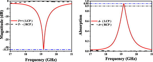
Figure 2. (a) Simulated transmission of the single spiral structure. (b) Simulated absorption of the single spiral structure.
Download figure:
Standard image High-resolution imageIn this paper, a band expansion absorber with high selectivity and strong chirality is also proposed, with four double-layer helical structures corresponding to four frequencies. By adjusting the size of each helix, the structure parameters and relative distances, four frequencies closer, hence the band expansion can be realized. Figure 3 shows the transmission curves for LCP and RCP. The optimized arrangement can realize the absorption above 90% of LCP waves ranging from 17.55 to 18.13 GHz, whose relative width (the calculation formula is 2 × (fH − fL)/(fH + fL)) is 6.8 times the bandwidth of the original single structure and the polarization extinction ratio is around 27 dB. Simultaneously, between 17.2 and 18.4 GHz, more than 85% of RCP waves are not absorbed.
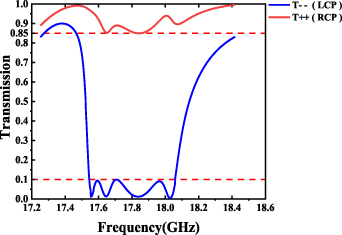
Figure 3. Transmission in the band-enhanced design.
Download figure:
Standard image High-resolution image4. Parameter discussion
The thickness of the medium matters a lot in the design of absorbers. When the thickness h is 0.8 mm, a better impedance matching can be achieved to realize the maximum absorption for LCP. As seen in figure 4(a), as h decreases from 0.85 to 0.75 mm, the absorption peak frequency shifts from 18.7 to 19.4 GHz.
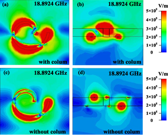
Figure 4. Comparison of the electric field distribution of a single spiral structure at the resonant frequency (18.8924 GHz) with and without the column. (a) and (c) Vertical view; (b) and (d) lateral view.
Download figure:
Standard image High-resolution imageThe influence of the radius of the column is taken for deliberation. It is found that the radius r connects the upper and lower helix and changes the current distributions. With a view to the discussion above, r= 0.3 mm is adopted for the optimal parameter value (figure 4(b)). As r increases from 0.1 to 0.3 mm, the absorption peak frequency shifts from 18.756 to 19.172 GHz.
At the same time, the discussion based on the proposed two structures with and without the plasma column is shown below (figures 5(c) and (d)). The absorption of the single-frequency structure deteriorates to half as much as before. Although the band extension structure absorbs RCP scarcely, only multi-frequency absorption peaks can be generated for LCP with the absorption rate reduced greatly. From the perspective of the electric field distribution, figure 4 illustrates the absorption mechanism in which the plasma column connects the upper and lower helices to produce stronger magnetic resonance, which possesses the capacitance characteristics. If the column is removed, only the upper and lower inductors are independently distributed, so the perfect resonance effect will not be achieved.

Figure 5. (a) Discussion of the FR-4 medium thickness h. (b) Discussion of the column radius r. (c) Discussion of single structure with or without a column. (d) Discussion of band extension structure with or without columns.
Download figure:
Standard image High-resolution imageThe electromagnetic wave we are taking into account above is the vertical incidence, but in the natural environment, the incident direction of the electromagnetic wave is from all directions. Therefore, we have systematically studied the wave absorption of the MM at a wide angle of incidence. Figure 6(a) shows the absorptivity curve of a single spiral structure when the incident angle is kept between −25° and 25°. The absorptance can be held above 90% between −10° and 15° at 19.156–19.244 GHz, above 80% between −20° and 18° at 19.1–18.25 GHz, and above 90% between −25° and 23° at 19–19.27 GHz. Furthermore, we discuss the polarization angle of the model (figure 6(b)), which can achieve the perfect effect of 360° polarization insensitivity, and the absorption for LCP above 90% ranging from 19.0675 to 19.175 GHz.
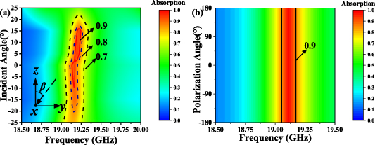
Figure 6. (a) Discussion on incident angle. (b) Discussion on polarization angle.
Download figure:
Standard image High-resolution image5. Physical mechanism discussion
When the incident wave passes through the helical structure on both sides of the substrate, the inductive current is generated in the helical structure. The four lowest transmission frequencies (17.555, 17.645, 17.836, 18.032 GHz) for LCP in-band expansion model are selected to observe LCP current and electric field distribution (figures 7(a)–(g) and 8(a), (c), (e), (g)). The middle part of the two spiral structures converges to a large amount of different electric fields, which makes the middle part of the spiral structure form an internal electric field and produces a large coupling capacitance. The reverse currents accumulated between the neighboring upper and lower rotation arms will lead to the production of magnetic dipoles, which further generate strong magnetic resonances for energy dissipation. Simultaneously, it is shown that when the incident wave is LCP, the electric field distribution on the upper and lower spiral surfaces is symmetrical. However, the RCP incident wave almost does not produce electrical induction (figures 7(b)–(h) and 8(b)–(h)), interacting with the CMMA weakly.
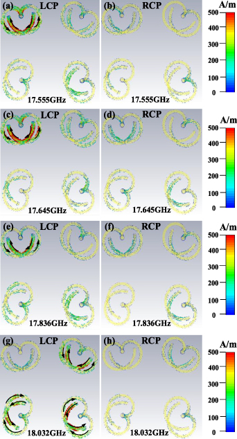
Figure 7. Current distribution at 17.555, 17.645, 17.836 and 18.032 GHz. (a), (c), (e), (g) LCP incident, (b), (d), (f), (h) RCP incident.
Download figure:
Standard image High-resolution image
Figure 8. Electric field distribution at 17.555, 17.645, 17.836 and 18.032 GHz. (a), (c), (e), (g) LCP incident. (b), (d), (f), (h) RCP incident.
Download figure:
Standard image High-resolution image6. Improvement of the model
The single spiral design after reducing the size and adjusting parameters can also act on THz bands (see table 3 and figures 9(a) and (b)). The frequency (FR-4) medium originally applied at GHz is changed to polyimide (loss-free) here whose electric constant is 3.5. Synchronously, gold, with the conductivity being 4.561 × 10⁷ S m−1, is used in place of the plasma material above. THz waves overlap both millimeter and infrared waves, and lie at the intersection of electronics and photonics. There is no denying that their broad and special properties have driven THz technology development.

Figure 9. (a) A single spiral structure from vertical view in THz. (b) A single spiral structure from lateral view in THz. (c) Stimulated transmission of the single frequency. (d) Stimulated absorption of the single frequency.
Download figure:
Standard image High-resolution image
Table 3. The parameters of the single spiral model in THz bands.
| Parameters | pTHz | hTHz | sTHz | l3 |
|---|---|---|---|---|
| Value (μm) | 150 | 15 | 6 | 15 |
| Parameters | l4 | wTHz | mTHz | rTHz |
| Value (μm) | 45 | 6 | 3 | 4.5 |
| Parameters | ϕTHz | |||
| Value (°) | 360 |
It is pleasing to note that the self-designed spiral structure is equipped to achieve the absorption and energy capture of THz waves, contributing to breaking through the core issues of THz calibration, regulation, conversion, and application. As shown in figures 9(c) and (d), the transmittance of such a structure for LCP is around −43.5 dB with a high polarization extinction ratio around 31.2 dB, and the absorption for both LCP and RCP waves around 95% and 2% can be realized in 1.337 THz.
7. Conclusions
Overall, the circular dichroism of CMMs enables such an absorber to achieve high selectivity for LCP at 19.172 GHz, while the RCP wave is basically not absorbed (around 0.2%). The spiral structure gives the absorber the characteristics of supporting a large incident angle and polarization insensitivity in 360°. The topology arrangement and array element adjustment broaden the absorption bands (17.55–18.13 GHz) for LCP above 85%. At the same time, the spiral antenna can be shrunk to act with the same performance in THz bands. The 95% absorption for LCP occurring at 1.337 THz can be used to reduce the radar cross-section of a target, having important applications in military hiding.
Data availability statement
The data generated and/or analyzed during the current study are not publicly available for legal/ethical reasons, but are available from the corresponding author on reasonable request.