
Export citation and abstract BibTeX RIS

Original content from this work may be used under the terms of the Creative Commons Attribution 4.0 license. Any further distribution of this work must maintain attribution to the author(s) and the title of the work, journal citation and DOI.
Introduction
From its inception holography has proven an extremely productive and attractive area of research. While specific technical applications give rise to 'hot topics', and three-dimensional (3D) visualisation comes in and out of fashion, the core principals involved continue to lead to exciting innovations in a wide range of areas. We humbly submit that it is impossible, in any journal document of this type, to fully reflect current and potential activity; however, our valiant contributors have produced a series of documents that go no small way to neatly capture progress across a wide range of core activities. As editors we have attempted to spread our net wide in order to illustrate the breadth of international activity. In relation to this we believe we have been at least partially successful.
This Roadmap is organized under three headings: Materials, Applications and Concepts . We hope this structure is not misleading as in some cases the contributions do not fit neatly under any single heading and in several cases, there is significant overlap between articles listed in all the three sections. Significantly, some articles discuss work in areas not traditionally addressed side by side with others. We sincerely hope our approach will lead to an increase in awareness and a cross-fertilization in this wonderful field.
Materials development and characterisation have always been of critically importance for the development of holography. The Roadmap begins with Wang et al (section 1) who briefly discuss novel materials for use in dynamic holographic displays. Tomita (section 2) then describes the development of nanocomposite photopolymers. Neipp and Frances (section 3) discuss the recording of holographic waveguides, while Gallego and Pascual (section 4) discuss shrinkage effects arising in photopolymers. Marovina et al (section 5) describe recent photorefractive materials and devices. Bruder et al (section 6) then discuss industrial-scale material production and volume holographic optical elements (vHOEs) fabrication.
Under the heading of Applications, Kostuk (section 7) leads with the use of non-imaging HOES for solar energy conversion. Odinokov (section 8) discussed holographic data storage (HDS) and security issues. Matoba et al (section 9) reviews some advances in Multimodal 3D data acquisition using digital holography (DH). Wachulak (section 10) describes the performance of extreme ultraviolet (EUV) and soft x-ray (SXR) holography and tomography employing compact short wavelength sources. Gorelaya et al (section 11) then discuss holographic wavefront sensors (WFS) and next Chmelik (section 12), describes advance in incoherent holographic microscopy (HM). Ferrara and Coppola (section 13) describe the applications of digital polarized holography in the sciences. Márquez and Beléndez (section 14) discuss the use of liquid crystal on silicon (LCoS) microdisplays for use in HDS systems. Yang and Yuste (section 15) discuss the two-photon holographic imaging and manipulation of neural activity in vivo. Finally, in this section, Bianco and Zanutta (section 16) describe the use of holography in astronomical spectrographs.
Under the heading Concepts, we begin with the description by Falldorf (section 17) of DH employing the spatial coherence function. Healy et al (section 18) describe the performance of autofocus in holographic imaging. Zhurminsky et al (section 19) discuss interference lithography for the fabrication of nanostructures. Situ and Wang (section 20) examine the applications of deep learning (DL) in DH. Abdurashitov and Tuchin (section 21) examine digital focusing in laser speckle contrast imaging (LSCI). Petrov (section 22) introduces ultrafast digital techniques and spatio-temporal metrology and Nomura (section 23) describes the evolution from the concepts of conventional DH to wide-sense DH. To conclude Morim and Saravanamuttu (section 24) describe the fabrication of functional 3D waveguide microstructures with nonlinear waves of light.
1. Materials for dynamic holographic 3D display
Yongtian Wang Wengao Lu and Haizheng Zhong
Beijing Institute of Technology, People's Republic of China
Status
Dynamic holographic techniques are emerging technology for displaying 3D images as movie [1, 2]. In general, the realization of holographic 3D display consists of the recording of the holograms by the interference of the object light and the reference light, and the reconstruction of the original object light by the diffraction of the hologram. Compared with parallax-based or scanning-based techniques, holographic display reconstructs the information of objects through a combination of amplitude and phase. With the developments of dynamic holographic recording and display media, holographic technique has become an active field toward dynamic 3D display. This section will discuss the status and future directions of recording and display media for dynamic holographic 3D display.
In general, there are two routes to realize dynamic holographic 3D display system, as shown in figure 1. One method is to load the computer-generated dynamic hologram into the spatial light modulator (SLM), followed by the reconstruction of the original object light through the diffraction using ordinary light source. Another method is to produce the dynamic holograms through the interference of the light the original objects or images and the reference light. Then the dynamic holograms are recorded using dynamic recording media, followed by the reconstruction of the light of the original objects or images using ordinary light source.

Figure 1. Typical two routes to realize the dynamic holographic 3D display system. (a), (b) Based on computer generated dynamic holograms, (c), (d) based on computer generated dynamic images. (a), (c) Virtual dynamic images viewed by viewers, (b) & (d) real dynamic images received by optical conversion media.
Download figure:
Standard image High-resolution imageThe latter method requires excellent coherent light source, for example, laser, to record dynamic holograms. The dynamic original images are provided by the reflected light of moving objects or generated by computers, and then the images are uploaded onto an SLM. Dynamic holographic recording medium is the key to realize dynamic holographic 3D display. Those candidates include photorefractive materials [1, 2], photochromic materials [3] and liquid crystals (LCs) [4], which can respond regularly to uneven light fields.
In addition, there are two ways that the original dynamic images to be observed, as shown in figure 1. One is that dynamic virtual images are obtained through diffraction, and can be observed after transmitted through optical systems, including optical waveguides, holographic reflection gratings and so forth. The holographic reflection gratings can be obtained by holographic exposure using permanent recording materials, for example, photopolymer [5], and has been used in head-mounted holographic 3D display system. The other is to obtain dynamic real images that can be received by bulk luminescent materials after transmitted through optical systems. In this way, the dynamic stereoscopic images can be observed in full space.
Current and future challenges
Although dynamic holographic 3D display technology is considered as a promising technology in the field of dynamic 3D display in the future, the application of this technology is still limited because of the immature development of the key materials in the display system. The holographic 3D display system introduced in the previous section mainly contains two kinds of media, including dynamic holographic recording media and receiving media. We will focus on the developments and perspective of these materials.
As for holographic recording media, not only many kinds of conventional materials, including silver halide, dichromate gelatin, photopolymer and other organic or inorganic materials, but also a series of new materials, including graphene [6], metasurface [7], plasmonic materials [8], have been taken seriously for static holographic recording. However, the above media are permanent holographic recording media and cannot be used for dynamic holographic recording. Dynamic holographic recording and displaying require that the information written before can be erased when the new information is being written. Therefore, it required that such materials can respond regularly to dynamic uneven light fields.
Organic photorefractive materials, photochromic materials and LCs have been extensively studied for dynamic holographic recording and they have been applied in dynamic holographic 3D display system, as shown in figure 2. However, there are still some problems to be solved to improve dynamic performance.

Figure 2. Principle of dynamic holographic 3D images recorded by different materials: (a) photorefractive materials, (b) photochromic materials, (c) liquid crystals. (d) Principle of up-conversion volume display, including two-beam and one-beam pumping method.
Download figure:
Standard image High-resolution imageFor organic photorefractive materials, because of the slow response in solid-phase, it is often necessary to impose external electric field of tens of volts per micron in order to improve the response rate and the nonlinear optical properties [2]. To obtain higher first-order diffraction efficiency, the thickness of the films are usually tens of microns to satisfy the volume holographic diffraction conditions. Therefore, it is common that the external electric field exceeding several kilovolts is applied, which limits the application of organic photorefractive materials. Photochromic materials are kinds of local response materials when used in dynamic holographic recording [3]. Although the response rate of is very fast and the external electric field is non-essential, the thickness of the photochromic film applied in holographic recording is usually nanoscale due to the large absorption coefficient. Therefore, it is difficult to satisfy the volume holographic recording condition, which results in that the first-order diffraction efficiency is very low and the high-order diffraction cannot be eliminated. For LCs, although the response time can be as short as several microseconds, the thickness is also not high enough to satisfy the volume holographic recording condition, which lead to the appearance of high order diffraction [4]. Meanwhile, because most of the diffraction light act as zero-order noise, it is difficult to improve the first-order diffraction efficiency. Therefore, it is more suitable for LC materials to be applied in small-scale dynamic holographic display system. Recent progress has shown that doping quantum dots (QDs) into LCs can improve the diffraction efficiency [10].
For the observation of the holographic 3D images, it is more convenient to observe the virtual image diffracted by the dynamic holograms. However, the field of view (FOV) of the SLMs is usually less than 30°, and hence this observation mode is more suitable for near field and fixed-point observation display systems, for example, head-mounted holographic 3D display system. This problem can be solved by the real image observation method, in which the stereoscopic images can be observed in full space. For the image receiving media, the luminescence properties are the key factors. The materials used as receiving media include organic or inorganic down conversion or up-conversion materials.
Among them, up-conversion materials, including rare earth up-conversion materials, organic dye up-conversion materials and so forth, bring better display effect because they do not bring the noise of light beam penetration. However, the improvement of quantum yields has been a big challenge for the application of receiving the holographic 3D images [9]. Considering this, the triplet-triplet annihilation up-conversion hold the potential to improve the efficiency, although they are now limited in liquids or soft gels.
Advances in science and technology to meet challenges
Appropriate recording and display media are necessary for holographic 3D display system. For holographic recording, in order to realize bright and real-time display, the refresh frequency of the recording media should exceed 60 Hz, and the zero-order diffraction noise and the high-order diffraction noise should be reduced to improve the first-order diffraction efficiency. At present, the blue phase LCs have attracted the attention of researchers because of their high response rate and low necessary external electric field [4]. To improve the definition of the holographic 3D images, the zero-order diffraction noise can be filtered by high-pass filtering. For real image receiving media, high fluorescence quantum yields are the key parameters for the up-conversion materials. Compared with conventional up-conversion luminescent materials, including rare earth and organic dyes, QDs attracted more attention in recent years due to their good stability and high quantum yields [9, 10].
Concluding remarks
Holography is a promising technology for dynamic 3D display. However, it lacks suitable materials to meet the requirement for dynamic recording and display. LCs and QDs may be the focus in the future, for their high response rate and high quantum yields, respectively, but rational materials design is very necessary.
Acknowledgments
This work is sponsored by National Natural Science Foundation of China (61722502; 61420106014),
2. Photopolymerizable nanocomposite materials for holographic applications
Yasuo Tomita
University of Electro-Communications, Japan
Status
Photonic nanostructured materials such as photonic crystals and metamaterials possess spatially ordered arrangements and they have been paid considerable attention to their tailored linear and nonlinear optical properties and to their ability of non-conventional light control. Another type of nanostructured materials involves either random arrangements of nanoparticles embedded in a transparent host material or composite materials finely interspersed/altered one another. These nanocomposites include Maxwell-Garnett, Bruggeman and layered composite geometries [11]. They usually exhibit the local-field effect that can be used to control the linear and nonlinear optical properties. However, these nanostructured materials are usually photo-insensitive, so that light assembly of their arrangement has never been possible.
A photopolymerizable nanocomposite material, the so-called photopolymerizable nanoparticle-polymer composite (NPC) [12], is a novel photo-configurable nanostructured material, in which inorganic or organic nanoparticles are highly dispersed in a photopolymer host. The holographic grating formation in an NPC is shown in figure 3. Photoinitiator species locally generate free radicals by their dissociation under two-beam interfering holographic exposure and the subsequent reaction of free radicals with monomer leads to the photopolymerization reaction between monomer radicals and unreacted monomer in the bright regions. This polymerization process lowers the chemical potential of unreacted monomer in the bright regions, leading to the diffusion of unreacted monomer from the dark to the bright illuminated regions. Because nanoparticles are photo-insensitive and their chemical potential increases as a result of the monomer consumption in the bright illuminated regions, nanoparticles counter-diffuse from the bright to the dark illuminated regions. In this way the mutual diffusion and the phase separation of monomer and nanoparticles lead to holographic assembly of nanoparticles under holographic exposure [13, 14]. This chemical reaction process results in the formation of a refractive index grating due to the density and compositional differences between the bright and the dark illuminated regions. Since one can select a suitable combination of nanoparticles and photopolymerizable monomer with a large difference in their refractive indices, spatially periodic refractive index changes with large saturated refractive index modulation amplitudes (nsat) provide higher contrast photonic lattice structures in large size of the order of 1 cm than those formed in conventional all-organic photopolymer materials. In addition, the inclusion of nanoparticles in polymer contributes to the substantive improvement of mechanical and thermal stability of the formed photonic lattice structure. Furthermore, since NPCs allow a wide choice of constituent materials, one can design NPCs for particular target applications in electromagnetic and matter wave optics as shown in subsequent sections. Applications of using NPCs reported so far include 3D image recording/reconstruction, holographic data storage (HDS) [15], security holograms (SH), holographic sensors, nonlinear optics, distributed feedback lasers, and holographic control of slow-neutron beams [12].

Figure 3. Holographic assembly of nanoparticles in an nanoparticle-polymer composite material (a) before and (b) after holographic exposure. Electron-probe micro-analyzer images of (c) Si (nanoparticles) and (d) S (the formed polymer) atomic density distributions after holographic exposure.
Download figure:
Standard image High-resolution imageCurrent and future challenges
So far, volume holographic recording in photopolymerizable NPCs dispersed with inorganic nanoparticles such as TiO2, SiO2 and ZrO2 nanoparticles to (meth)acrylate monomer capable of chain-growth polymerization were demonstrated. It was shown that nsat of the order of 0.01 was possible in the blue and the green with reduced polymerization shrinkage and high thermal stability [12]. In order to use inorganic nanoparticle dispersed NPCs for optical recording media in HDS, Tomita et al proposed NPCs with thiol-ene/thiol-yne monomers capable of the step-growth polymerization [16]. It was shown that a plane-wave holographic grating recorded in such thiol-ene/thiol-yne based NPCs satisfied all the requirements for HDS media, that is, nsat ≥0.005, the material recording sensitivity higher than 500 cm J−1 and polymerization shrinkage lower than 0.5%. Subsequently, they demonstratedshift-multiplexed and coaxilal holographic digital data page storage in thiol-ene/thiolyne based NPCs [12]. High dispersion (>20 vol.%) of inorganic nanoparticles in host monomer always requires careful surface treatment for their uniform dispersion without aggregation. In order to relax this severe requirement, Tomita et al proposed NPCs dispersed with hyperbranched polymers (HBPs), nanostructured polymer possessing highly branched main chains, as organic nanoparticles [12]. It was shown that volume gratings recorded in acrylate monomer dispersed with HBPs gave nsat close to 0.01 in the green. Recently, it was shown that the use of a new HBP having the ultrahigh refractive index of 1.82 can increase nsat further as large as 0.022 (currently, 0.045) in the green with good optical quality [17], suggesting its application to holographic diffractive elements for wearable headsets used in augmented and mixed reality. In such an application a volume grating with nsat larger than 0.02 and the film thickness of the order of 10 m is required to realize high diffraction efficiency and large Bragg aperture at the same time. A further increase in nsat is still desired to improve the performance.
One can also utilize the composite nature of photopolymerizable NPCs for artificial nonlinear optical materials when either guest or both guest and host have distinct optical nonlinearities. In this case optical nonlinearities of metal-dielectric nanocomposites are accompanied with the surface plasmon resonance (SPR) that results in the local-field enhancement [11], leading to the enhancement of optical nonlinearities of metal-dielectric nanocomposites. The nonlinear optical properties of holographically recordable NPCs dispersed with nonlinear nanoparticles, HBP-metallic (Au or Pt) nanoparticle complex, were investigated [12]. It was shown that they exhibited the dielectric confinement effect near SPR and that the magnitude of their effective third-order nonlinear optical susceptibility was of the order of 10−10 esu at a wavelength of 532 nm. Optical nonlinearities and volume holographic recording in a semiconductor CdSe QDs dispersed NPC film were also reported. Because of the composite structure cascaded high order optical nonlinearities were observed [12]. Associated nonlinear Bragg diffraction from the one-dimensional (1D) photonic lattice structure recorded in the NPC film were also observed, suggesting the possibility of constructing multi-dimensional nonlinear photonic lattice structures.
NPC gratings can also find completely different applications from those in optics and photonics as described above. They can be used to control non-electromagnetic slow-neutron beams for their manipulation by diffraction from NPC gratings, where an incoming slow-neutron beam interacts with holographically assembled nuclei of nanoparticles via the nucleus–neutron interaction (strong force). In this way NPC gratings can be used for efficient slow-neutron optical elements such as mirrors and beam splitters to perform slow-neutron interferometry [18] for studies of nuclear physics, quantum physics, condensed matter physics, biology, life and medical sciences, materials science and industrial engineering. It was demonstrated that various manipulation schemes for the control of slow-neutron beams (e.g. beam splitting, triple beam division and total beam deflection) via transmission NPC gratings dispersed with SiO2 and ZrO2 nanoparticles were possible [12, 19]. Currently, development of more efficient and neutron-spin dependent NPC gratings has been underway to increase the neutron diffraction efficiency further and to perform neutron-spin control.
Advances in science and technology to meet challenges
Main challenges are always accompanied with those in the sample fabrication: the uniform dispersion of nanoparticles at high concentrations in photopolymer to fabricate a transparent film without substantive scattering loss. This requires sophisticated surface modification techniques on dispersed nanoparticles. Thanks to recent development of nanoscience and nanotechnology, it is now possible to uniformly disperse various types of nanoparticles at their high concentrations in photopolymer. For example, surface-modified QDs, nanodiamonds and magnetic nanoparticles can be used for photopolymerizable NPCs. Thin NPC gratings dispersed with nanodiamonds would result in high slow-neutron diffraction efficiency since the interaction of nanodiamond with slow neutron is approximately two times larger than that of SiO2 nanoparticles and thus provides a large value of nsat [20]. Also, NPC gratings dispersed with magnetic nanoparticles such as Fe3O4 would play a role in slow-neutron spin interferometer for slow-neutron beam's spin control and separation [20].
Concluding remarks
Photopolymerizable NPCs are photo-configurable nanostructured composite materials that can be used for holographic and other applications. We have described the mechanism of the holographic grating formation in NPCs and showed several holographic applications of NPC gratings in light and neutron optics. These successful demonstrations with high performance clearly show the usefulness of photopolymerizable NPCs for versatile applications in photonics, electronics, physics, nanotechnology, materials science, chemical/biomedical applications.
Acknowledgments
This work was supported by the Ministry of Education, Culture, Sports, Science and Technology of Japan under Grant Nos. 20360028, 23360030, 23656045, 15H03576 and 17K19072.
3. Photopolymers for the recording of holographic waveguides
Cristian Neipp and Jorge Francés
University of Alicante, Spain
Status
Since a few years ago, augmented reality (AR) or virtual reality (VR) has taken on importance in society: from video games programmed to play with VR glasses to glasses that act as mobile devices connected to the Internet.
The Google Glass was the pioneer in the market (launched in 2014) and the ones that have traveled the most since they incorporate functions such as camera, calendar, object recognition while driving, text translation and viewing of photos and videos, among other applications. But in recent years new devices have emerged that have allowed VR experiences to live. Thus, for example, Oculus presented in 2015 the Oculus Rift that, initially, were provided with loudspeakers, sensors to detect rotational movements. HTC VIVE and Microsoft Hololens have also offered high-quality AR experiences.
There are many and varied applications of AR, for example in drone piloting or in the treatment of phobias and traumas with demos in which the user was not a mere spectator, but could interact with virtual objects/people. In addition, patients with autism are treated to create real situations such as interviews, appointments, etc. Likewise, the surgical training received at some universities, such as Stanford University, should be highlighted.
Holographic techniques have been of key importance for manufacturing this type of device. For example, using a hologram or volume diffraction grating as an optical coupler in a waveguide (glass substrate) it is possible to create AR effects [21]. Figure 4 shows a system based on two holographic couplers.

Figure 4. (a) Holographic waveguide. (b) Diffraction grating couplers; (c) holographic waveguide (couplers are brighter spots).
Download figure:
Standard image High-resolution imageThe first hologram in front of the lens couples the light to the waveguide in total reflection condition, while the second hologram couples the beam out of the waveguide. In order to work as couplers the transmission holographic gratings should couple the incident light between air and the glass substrate accomplishing total internal reflection. In figure 4,  and
and  are the propagation vectors of the incident and diffracted beam respectively,
  is the grating vector and θg
is the critical angle inside the photopolymer. The experiments conducted to obtain the holographic waveguide of figure 4 [22] were made under the illumination with a He–Ne laser, with wavelength, λr
= 633 nm, so that assuming an average refractive index of the photopolymer of ng = 1.478, the critical angle in the photopolymer is θg
= 42.57°. For the glass substrate, with refractive index of 1.51 the critical angle is θc
= 41.47°. Now it is important to notice that the gratings acting as grating couplers must be slanted gratings (see figure 4(b)). This is because the grating must couple an incident wave perpendicular to the interface air grating to a wave forming an angle θg
with the normal to the interface glass air. In fact, defining the grating vector as
is the grating vector and θg
is the critical angle inside the photopolymer. The experiments conducted to obtain the holographic waveguide of figure 4 [22] were made under the illumination with a He–Ne laser, with wavelength, λr
= 633 nm, so that assuming an average refractive index of the photopolymer of ng = 1.478, the critical angle in the photopolymer is θg
= 42.57°. For the glass substrate, with refractive index of 1.51 the critical angle is θc
= 41.47°. Now it is important to notice that the gratings acting as grating couplers must be slanted gratings (see figure 4(b)). This is because the grating must couple an incident wave perpendicular to the interface air grating to a wave forming an angle θg
with the normal to the interface glass air. In fact, defining the grating vector as  and taking into account that the slanted angle can be calculated by ϕ = atan (Ky
/Kx
)−π/2, the angle formed by the interference fringes with the substrate is in this case of 69.3°. The spatial frequency, f, of the gratings can be calculated as
and taking into account that the slanted angle can be calculated by ϕ = atan (Ky
/Kx
)−π/2, the angle formed by the interference fringes with the substrate is in this case of 69.3°. The spatial frequency, f, of the gratings can be calculated as  which in this case is of 1690 lines mm−1. Therefore, the recording material must be capable of recording these high spatial frequencies with sufficient stability for the fringes. It is evident, then, that an essential aspect in the production of waveguides is the recording material. Some of the most used holographic recording materials are photosensitive polymers [23
–
27], presenting high flexibility, controllability, versatility, reasonably long half-life, low price, etc [28]. The photopolymerizable systems used in holography basically consist of a polymeric film that acts as a matrix or 'binder', a photoinitiator system, formed by one or more sensitizers, an electron donor and one or more monomers. In recent years, biocompatible variants have been developed [29], modifying their composition for the corresponding application, and the combination of LC molecules with a photopolymer in a form called LCs dispersed in holographic photopolymers [30] that provide dynamic characteristics useful for a multitude of applications.
which in this case is of 1690 lines mm−1. Therefore, the recording material must be capable of recording these high spatial frequencies with sufficient stability for the fringes. It is evident, then, that an essential aspect in the production of waveguides is the recording material. Some of the most used holographic recording materials are photosensitive polymers [23
–
27], presenting high flexibility, controllability, versatility, reasonably long half-life, low price, etc [28]. The photopolymerizable systems used in holography basically consist of a polymeric film that acts as a matrix or 'binder', a photoinitiator system, formed by one or more sensitizers, an electron donor and one or more monomers. In recent years, biocompatible variants have been developed [29], modifying their composition for the corresponding application, and the combination of LC molecules with a photopolymer in a form called LCs dispersed in holographic photopolymers [30] that provide dynamic characteristics useful for a multitude of applications.
Current and future challenges
One of the most important aspects to take into account if you intend to manufacture optical elements of VR refers to the fact that to achieve an adequate resolution to the human eye it is necessary to use complex systems. If these systems are based on conventional optics the result is a bulky optical system for AR. In addition, optical solutions currently do not allow a wide field of vision to be obtained. On the other hand when HOEs are used there is associated chromatic dispersion, so it is difficult to faithfully reproduce an image of rich chromaticity. Likewise, the HOEs have limitations for high spatial frequencies. This is because at high spatial frequencies and therefore, small periods, the non-local effects begin to have greater importance.
Advances in science and technology to meet challenges
To solve the above problems it is necessary to move in different directions. For example it is possible to create light see-through vision systems by replacing the conventional optics with HOEs, obtaining devices with different functions based on the multiplexing capacity of the HOES [31, 32]. But for this it will be necessary to improve the chromatic dispersion of the HOEs [33, 34]. The other necessary advance is in the optimization of photosensitive materials of holographic recording for high spatial frequencies. It is therefore necessary to optimize the compositions of the polymers to work at high spatial frequencies for example using chain shorteners such as 4,4'-Azobis (4-cyanopentanoic acid) (ACPA). In addition as explained in the introduction the stability of the fringes for the slanted gratings acting as couplers or as part of a more sophisticated HOE must be guaranteed. It is well known that due to shrinkage after recording [35, 36] the slant angle of the gratings changes, what should be avoided in these devices. Studies must be conducted in order to increase the diffraction efficiency of high spatial frequency gratings and stabilize the fringes of the slanted gratings. Preliminary work has been made to address these problems evaluating the fabrication of waveguides in three different photopolymers using three different geometries. The photolymers studied were polyvinyl alcohol acrylamide, polyvinil alcohol/acrylamide (PVA/AA), secondly a nanoparticle-(thiol-ene) polymer composite, NPC, and on the last place a penta/hexa-acrylate based polymer with dispersed nematic LC molecules, PLC In all of them, the display can be recorded with interesting percentage of incident light guided through the substrate, but for the PVA/AA and NPC, the diffraction efficiency is limited for different reasons in each case. The most promising results were obtained for PCL material. In this case, a maximum diffraction efficiency was achieved with a thickness lower than 60 µm with energetic sensitivity close to the one of PVA/AA materials.

Figure 5. Ewald's sphere and recording (right) and read out (left) geometries for three slanted gratings. Geometry A: designed for normal incidence of red light. Geometry B: less inclination of the grating fringes. Geometry C: higher inclination of the grating fringes.
Download figure:
Standard image High-resolution imageConcluding remarks
We have concentrated our attention on the issues related with the use of photopolymer materials for the recording of holographic waveguides. From our research in this field, it has been demonstrated the capability of photopolymer materials for the recording of holographic gratings acting as couplers in a waveguide system. There are still limitations that must be solved such as the chromatic dispersion of the HOE's and the stability of the fringes in the slanted gratings.
Acknowledgments
This work was supported by Ministerio de Economía, Industria y Competitividad (Spain) under projects FIS2017-82919-R (MINECO/AEI/FEDER, UE) and FIS2015-66570-P (MINECO/FEDER), by Generalitat Valenciana (Spain) under project PROMETEO II/2015/015 and by Universidad de Alicante under project GRE17-06.
4. Shrinkage in holographic recording materials: photopolymers
Sergi Gallego and Inmaculada Pascual
University of Alicante, Spain
Status
After the invention of the laser, the first coherent light source, in the 1960s, the technique of holography proposed by D Gabor could be really implemented. Nevertheless, the main drawback was the design holographic recording material. Early holograms used silver halide photographic emulsions as the recording medium, but the results were not enough efficient. Then began an intensive research on the developing of holographic recording materials. As a result, holograms have been recorded in dichromatic sensitized gelatin, photoresist, electro-optical crystals, photochromic films and glasses, thermoplastics, photopolymers, amorphous semiconductors, and dye, MnBi, vesicular, and diazo films, as well as the more standard silver halide emulsions [15, 37].
In order to characterize these new holographic recording materials, many parameters must be measured such as: diffraction efficiency, absorption/refractive index/thickness modulation, spatial resolution limit, required exposure or shrinkage. Depending on the application these parameters should take determinate range of values. For example, for holographic data storage systems, the recording material should fulfill sensitivity, between of 100–1000 mJ cm−2 to achieve full dynamic range; refractive index modulation, minimum of 5 × 10⁻³; and shrinkage, maximum of 0.5% [38]. Shrinkage is one of the most complicate parameters to fit, therefore different methods were proposed to achieve this challenge. In general, it is assumed that shrinkage occurs after the gratings are formed. The assumption that one side of the material is attached to a rigid substrate is the basis of the fringe rotation model [39], this can be a reminiscence of the initial steps of the holography where silver halide emulsion was the most popular holographic recording material [40]. On the other hand, in general a common approach to modelling Bragg shift in replay properties it is to assume negligible refractive index change [41]. Measuring where the Bragg's condition is located to achieve maximum diffraction efficiency in the reconstruction scheme is the standard method to measure shrinkage. The values provided by this technique sometimes slightly differ from results provided by mechanical systems; some authors suggested that this difference in optical measured shrinkage is the effect of the average refractive-index change [36, 42]. Photopolymers are one of the most attractive holographic recording materials due to their good and versatile optical properties [43]. Nevertheless, the shrinkage is also more complicate to fit due to the mass transfer involved in diffusion process [44, 45].
Current and future challenges
Different techniques have been proposed in order to quantify the shrinkage in photopolymers [35, 46 – 49]. The maximum shrinkage has placed when there is no diffusion [46]. Other methods estimate also the change in the spatial frequency [48], and the last contribution takes into account the complete angular-spectral analysis [49]. But in general these methods are based on Bragg-angle detuning measurements. The most common geometrical approximation used in the bibliography is reproduced schematically in figure 6. In this figure the recorded fringes are represented by continues lines and separated by a spatial period Λ. The fringes after shrinkage are represented by discontinues lines and separated by a new period Λ'. K is the grating vector; ρ and σ are the propagation vectors of the recording beams inside the recording material; d is the initial thickness and d' the thickness after shrinkage; L is the maximum length of the fringes and Λx and Lx are two constants independent of the shrinkage and derived from the assumed conservation of the x component of K, Kx in this model.

Figure 6. Standard model of shrinkage proposed. Light travels to the positive direction of axis Z. The Ewald's sphere.
Download figure:
Standard image High-resolution imageCombining the model of figure 6 with the diffraction theory [36] we can find the relation of the variation in the fringe spacing with the shrinkage.

where  is the shrinkage and
  is the variation of the fringe spacing. The initial spatial period is obtained from the two interference beams angles, and to obtain the fringe spacing after the holographic grating recording there are two ways. Either assuming that the component Kx
remains constant and measuring only the +1 Bragg's angle or taking into account +1 and −1 diffracted order angles and re-calculating the whole grating vector. An alternative method consists in obtaining the period from the Bragg's condition; in general, Bragg's condition can be obtained from the next equation:
is the variation of the fringe spacing. The initial spatial period is obtained from the two interference beams angles, and to obtain the fringe spacing after the holographic grating recording there are two ways. Either assuming that the component Kx
remains constant and measuring only the +1 Bragg's angle or taking into account +1 and −1 diffracted order angles and re-calculating the whole grating vector. An alternative method consists in obtaining the period from the Bragg's condition; in general, Bragg's condition can be obtained from the next equation:

where θ is the angle between the replay vector and the fringes. As usually after shrinkage it is difficult to precise the slanted angles of the fringes, it is possible to use an alternative way where Bragg's condition is expressed as a function of the angle formed by ρ and σ inside the material, ϕ, as follows:

and here we have to measure the two Bragg's angles, corresponding to +1 and −1 diffracted orders.
Advances in science and technology to meet challenges
We have recently analyzed the differences between measuring the shrinkage with the different methods proposed. For example, the proposed in [43] using only the Bragg's deviation form one diffracted order (+1) and two (+1 and −1) proposed in [36]. Also we have introduced the possibility in our study the Bragg's deviation from higher orders (+2 and +3). We want to know if it affects significantly the values of shrinkages obtained. We have applied the shrinkage measuring method for three different photopolymers families, many different exposure times and large range of sample thickness, from 30 µm to 300 µm. In table 1 we present the data from a grating recorded in PVA/AA material with thickness of 73 µm and final diffraction efficiency, DE, of 80% [36].
Table 1. Measured angular positions in air of the diffracted orders ±1 and the value of Kx.
| Recording time (s) | Angle order +1(°) | Angle order −1(°) | Kx (µm−1) ±0.01 |
|---|---|---|---|
| 5 | 3.750 | −34.050 | 6.21 |
| 10 | 3.740 | −34.077 | 6.21 |
| 20 | 3.670 | −33.999 | 6.19 |
| 30 | 3.644 | −33.994 | 6.18 |
| 40 | 3.564 | −33.955 | 6.16 |
| 50 | 3.481 | −33.792 | 6.13 |
| 80 | 3.322 | −34.001 | 6.13 |
There are significant differences if we analyze the data provided in table 1 taking into account only one angle, [43], second column, or both [36], third column. The results are shown in table 2.
Table 2. Measured shrinkage.
| Recording time (s) | % Shrinkage 2 angle ±0.14 | % Shrinkage 1 angles ±0.14 |
|---|---|---|
| 10 | 0.08 | 0.07 |
| 20 | 0.05 | 0.00 |
| 30 | 0.17 | 0.00 |
| 40 | 0.29 | 0.80 |
| 50 | 0.62 | 0.67 |
| 80 | 1.31 | 0.35 |
After our analysis we demonstrated that for holographic recording materials it is mandatory the measurement of more than one Bragg's angle. The inaccuracies can be huge if only the deviation from the main diffracted angle is considered. Furthermore, to fit the angular response of the slanted gratings we have used different electromagnetic methods with good agreement between simulations and experiments. In figure 7 we depicted the experimental angular scan around the +2 Bragg's condition for a hologram recorded in PVA/AA material fitted by a rigorous coupled wave theory [50]. From the fitting we extract the optical thickness, d, refractive index modulation, n1, and the absorption and scattering coefficient, α: d = 75 µm, n1 = 0.00325, α = 0.0005 µm−1. It worth noting that shrinkage continues growing even when the DE looks constant.

Figure 7. Experimental data and simulation of the DE around the 2 n Bragg's angle.
Download figure:
Standard image High-resolution imageConcluding remarks
We have detected a significant variation of the component Kx of the grating vector in some photopolymers, this surprising fact makes impossible to apply some of the classical methods to measure the shrinkage consisting in the detuning of the first Bragg's angle [43]. As an alternative, we recommend the mandatory measurement of the Bragg's angles for both orders ±1.
Acknowledgments
This work was supported by Ministerio de Ciencia, Innovación y Universidades (Spain) under projects FIS2017-82919-R (MINECO/AEI/FEDER, UE) and FIS2015-66570-P (MINECO/FEDER) and by Generalitat Valenciana (Spain) under project PROMETEO II/2015/015.
5. Advances in holographic photorefractive materials and devices
Vera Marinova1,2, Shiuan Huei Lin1, Ken Yuh Hsu1
1 National Chiao Tung University, Taiwan
2 Institute of Optical Materials and Technologies, Bulgarian Academy of Sciences, Bulgaria
Status
Holography offers a unique way for recording and reconstructing the wave front of an optical wave, carrying information for both the amplitude and phase of real 3D image [51]. The challenge to display optically a full parallax of 3D object has been constantly driving the revolution of display technologies over the past decade. Nowadays, the realization of wide-angle 3D holographic images requires generation of subwavelength-scale refractive-index/phase modulation. To meet this requirement, the materials and devices based on photorefractive effect continue to play a fundamental role. In this section, we first review characteristics of photorefractive materials, and then describe advances in hybrid holographic devices using inorganic and organic materials for creating stronger photorefractive response to meet these challenges.
Generally, holographic materials are divided to the permanent and rewritable one. Conventional holograms are usually recorded on silver halides, photopolymers or dichromated gelatin (DCG) and reproduced by coherent (lasers) or incoherent (light-emitting diodes) light sources. Although the above materials are highly developed and gained great progress in a past, they lack the capability of updating and rewriting, which limits their use [52]. Alternatively, photorefractive materials such as inorganic crystals, organic photopolymers and amorphous glasses; photorefractive LCs and recently hybrid organics-inorganics structures offer excellent scenarios for updatable and rewritable holographic recording.
A common remarkable feature of the photorefractive materials is their ability to detect and store the distribution of the optical intensity in form of spatial patterns of modulated refractive index. The effect originates by the light interference inside the photosensitive material and relays on photogeneration of charge carriers, their subsequent migration and redistribution among the traps, which results to an internal space charge field product (figure 8(i)). The photogenerated space charge field in combination with the electro-optic effect modulates the refractive index of the media [2, 52, 53]. Since all the processes are reversible, the refractive index change can be erased and formed many times and even when the illumination is stopped, the refractive index modulation continues as long as the charge distribution exists within the material. As a result, the photorefractive effect can be used to generate rewritable holograms.

Figure 8. Schematic diagram of (i) photorefractive effect, (ii) two-beam coupling in an inorganic crystal. Reprinted with permission from [54] © The Optical Society. (iii) Penetration of space-charge field in organic-inorganic hybrid structure. [55] John Wiley & Sons. © 2016 WILEY-VCH Verlag GmbH & Co. KGaA, Weinheim.
Download figure:
Standard image High-resolution imageMoreover, the photorefractive phenomenon allows a weak beam to grow exponentially with the distance (beam amplification), which makes the photorefractive effect exceptional among others nonlinear effects (figure 8(ii)). This optical gain, resulted by the asymmetric energy transfer, become a unique feature for amplifying the carried information and serve as main operation principle of 3D displays, novelty filters, phase conjugate wave generators, optical amplifiers, etc [53]. In addition, the photorefractive materials are reconfigurable: recording of optical information is possible at real time.
Inorganic crystals (ferroelectrics as LiNbO3, KNbO3, BaTiO3), sillenite crystals, semiconductors (InP:Fe, GaAs)), owing to their massive storage capacity (TBits cm−3), directional energy transfer and fast access rate (GBit s−1) have been regarded as the best materials for reversible storage and processing of information [2, 53, 54]. The most prominent for applications is LiNbO3 due to its superior refractive index modulation [2, 53]. Sillenite type crystals (Bi12SiO20, Bi12TiO20) are among the fastest inorganic materials so far due to their excellent photosensitivity (remarkable high photoconductivity) and high charge carrier mobility. They find applications in real-time holography, optical phase conjugation, optical information processing, optical interconnection, etc [54]. Moreover, the incorporation of transition metal ions, such as Fe, Mn, Ru and Rh, improve the sensitivity and the response time at near infrared (NIR) spectral range and enhance the photorefractive properties [55, 56].
Although inorganics can provide excellent photosensitivity (low intensity operation) and fast response time, as well as mechanical and environmental stability, the complicated crystal growth process and size limitation drawback reproducibility of large-scale holograms. Advanced potentials to develop updatable 3D holographic displays have been opened after the discovery of photorefractive polymers by Ducharme et al [57] in 1991. The photorefractive effect in photopolymers is induced by doping the polymer matrix with a high concentration of chromophores (molecules easily orientable by external electric fields) and the non-linear electro-optic effect is referred to quadratic electro-optic effect that produces an additional contribution to the total refractive index modulation. Currently, photorefractive organics offer a flexibility of large size production, easy fabrication and properties manipulation as well show 100% diffraction efficiency and very high figure of merit factor. An updatable holographic 3D display that provides realistic image without the need of special eyewear based on photorefractive polymer has been reported [1]. Also, multiplexed hologram recording has been demonstrated using a photorefractive polymer film with very high quality of 3D images, however, the relatively slow response time (100 ms) and necessity of high electric field operation require additional properties improvement, mainly in terms of updating the speed and spatial frequency interval.
Current and future challenges
Currently, the research community continues exploring challenges to develop novel materials with fast operation speed, high memory capability, submicron spatial resolution and low energy consumption. For example, to reach a wide viewing angle, the pixel pitch needs to be smaller than or comparable to the wavelength of light. Besides, to manipulate light–matter interactions, all optically controlled devices are critically needed.
Recent significant attempts complement the shortcomings and disadvantages of an individual material by constructing novel hybrid structures, which open opportunities the properties to be optimized independently and combined into a single device with enhanced functionality. Examples are hybrid structures assembled by large anisotropy, strong birefringence, structural flexibility and low cost, typical for organic materials with the excellent photosensitivity, photoconductivity and mechanical stability, provided by inorganics.
An idea, first proposed theoretically by Tabiryan and Umeton [58] consider a hybrid structure assembled by LC on photorefractive inorganic substrate (figure 9(a)), where the charge migration, trap density and space-charge field come from the inorganic substrate, whereas the beam amplification is provided by the LC layer. The operation principle relays on surface activated photorefraction and more specific on the photo-generated space charge field, acting as a driving force for LC re-orientation (consequently refractive index modulation) (figures 8(iii), 9(a) and (b)). The main significance of illustrated hybrid structure is the ability to act as holographic grating at Bragg matched coupling regime that allows sub-micron resolution (the phase matching conditions are satisfied only in one direction). As a result it is classified as novel type of non-linear optical components with attractive capabilities for light manipulation, coherent image amplification, to control the group velocity of modulated signal beam, etc. Moreover, it can serve as novel type of optically addressed SLM (OASLM or light valves) with high spatial resolution operating in transmission mode. The advantages of submicron resolution, simple fabrication and compactness open scenarios to design varieties of structures that meet the up-to-date requirements of 3D display technologies in the future.

Figure 9. (a) Schematic structure of all optically controlled organic-inorganic hybrid device which consists of photorefractive BSO:Ru crystal, polymer dispersed liquid crystal (PDLC) and glass substrate and two-beam coupling experiment, (b) simultaneous behaviour of both transmitted beams through the hybrid structure and PDLC reference sample (c) gain amplification depending of the grating pitch.
Download figure:
Standard image High-resolution imageAdvances in science and technology to meet challenges
In recent years, new emerging materials along with their challenges and prospects has been proposed and addressed in the holographic field.
Researchers are exploring solutions for wide viewing-angle and full-color floating 3D display in graphene based materials. For instance, photo reduction of thermally reduced graphene oxides by femtosecond (fs) pulsed beam introduce a giant refractive index modulation on the order of 10–2 to 10–1, which open a new horizon for multimode optical recording, information security, and holographic images. The result has been achieved through the subwavelength-scale multilevel optical index modulation. Currently the reduced graphene oxide enabled writes-once holograms.
Light-assisted approach when combining graphene on the surface of the inorganic substrate of LiNbO3 crystal has been reported recently based on space charge electric field [59]. The injecting of small amounts of charge carrier results the Fermi level of graphene to be significantly altered thus modifying its electrical properties. The authors present a method toward spatially resolved control of the charge transport properties of monolayer graphene that is both reversible and nonvolatile, allowing for electrostatic charge distributions to be written or erased in an all-optical fashion. The effect is capable of producing nonvolatile charge distributions of arbitrary shape, which can be erased by uniform illumination.
The outstanding mechanical strength of graphene also provides further prospect for flexible devices.
Other examples are optical metamaterials (periodically nanostructured artificial materials) which demonstrated ability to encode phase information for reconstructing images (phase holograms) and to manipulate light–matter interactions on spatial dimensions smaller than the wavelength of light [60].
Concluding remarks
Based on the unique nature of the photorefractive effect and optical amplification phenomena, photorefractive materials continue challenging for signal processing amplification and 3D display area. The next technological jump comes enabled by nanomaterials and inventive hybrid structures providing subwavelength-scale refractive-index modulation.
Acknowledgments
Supported by Ministry of Science and Technology (MOST), Taiwan Contract Nos. MOST 107-2221-E-009-120-MY3, MOST 107-2911-I-009-508 (Taiwan-Bulgarian PPP project) and Bulgarian Science Fund project DFNI Кп-06-H-28/8. V M acknowledges support by the European Regional Development Fund within the Operational Programme 'Science and Education for Smart Growth 2014–2020' under the Project CoE 'National center of Mechatronics and Clean Technologies' BG05M2OP001-1.001-0008-C01.
6. Industrial-scale recording material and mass production of vHOEs
Friedrich Bruder, Sven Hansen, Christel Manecke, Richard Meisenheimer, Christian Rewitz and Thomas Rölle
Covestro Deutschland AG, Germany
Status
The origins of optical holography are dating back to Lippmann photography more than a century ago [61]. Holography therefore was invented significantly earlier than the laser, which is a mandatory tool for recording of optical holograms. Surface gratings as a sub group of optical holograms are very well known. Recording and mass production technology are well developed and established in the surface grating case. As security feature and brand protection label those surface gratings are obvious to the daily user. Surface gratings or better surface diffraction are however much more commonly utilized in (directional) diffusors in backlight units of displays. The most widespread surface grating is most likely utilized in pre-recorded optical discs such as CDs, DVDs and Blu-Ray Discs [62]. Volume holograms, especially volume phase holograms however offer the advantage of recording various optical functions into the same volume (multiplexing) and total transparency in off Bragg conditions at the same time. The first is difficult to achieve with surface gratings and the latter is completely impossible to achieve with surface gratings, as those do not have any angle or wavelength selectivity. In volume holograms the thickness of the recording layer is the main controlling parameter for its angle and wavelength selectivity. Suitable recording materials for such volume phase holograms are mainly based on various material concepts of photopolymers [63, 64], DCG and silver halide materials, respectively. Photopolymers are herein superior as they offer an easy way to generate recording media with thicknesses ranging from ∼1 µm to few mm and allowing the control of the above mentioned selectivity while keeping a high transmission at the same time. Photopolymer development was also boosted in the past decades by the search of an easy-to-use recording material for holographic optical data storage.
Photopolymers deliver a very favorable property profile [65] and a well-designed photopolymer does not require any pre- or post-processing. Based on these insights, Bayfol® HX film was developed as an easy to record and reliable recording photopolymer film and is available at industrial scale. This customizable material defines the first step in the value and supply chain of a volume holographic industry. The basic characteristics of Bayfol® HX film, the modelling of its holographic recording mechanism as well as demonstration projects towards mass production technologies of vHOEs with Bayfol® HX film, ranging from recording of large scale master vHOEs—utilizing holographic printers—to roll to roll contact copy mass manufacturing of vHOEs are described in [66]. Bruder et al [66] also includes further useful references. These include topics like tuning the maximum index modulation n1 of a volume phase grating by optimization of the photopolymer formulation, the adaption of the spectral photosensitivity by the proper initiation system, or the adjustment of the mechanical modulus by the host matrix. While most industrial-scale photopolymers utilized today uses either IR/UV-initiation in printing plates or, in the case of semiconductor applications, e-beams or even higher energy beams, the distinct challenge of photopolymers for visual holographic optical recording requires a highly efficient and robust VIS-light recording chemistry. Herein, Bayfol® HX film marks a milestone since it implements recording sensitivity in the visible spectral range at affordable exposure dose. Especially the purely photo-chemical bleaching of the sensitizer chemistry allows for a fully dry processing [67]. The dry handling conditions are moreover compatible with the mechanically optimized properties as the unrecorded material is rather soft, thus allowing excellent optical contacting during lamination and becomes significantly stiffer post-bleach. The intrinsic mechanical moduli can—within certain limitations—be tuned to meet individual customer requirements [68]. Further insights from our modelling of the recording mechanism in Bayfol® HX film are described in [69, 70] dealing with the generation of 2nd harmonic gratings and forcing those to achieve a high index modulation n2 by tuning the recording conditions and/or the photopolymer formulation. Some useful applications of this feature are proposed in the given [69, 70], too. Wavelength multiplexing is essential to a recording material to be able to generate full colour volume image or display holograms. This ability is even more crucial in modern applications of vHOEs as thin and lightweight full colour optical combiner in head-mounted displays (HMD) or for head-up displays (HUD) with enhanced performance. Those combiners are usually free space off-axis (focusing) mirrors that are able to operate on RGB projecting light sources. How to achieve this wavelength multiplexing in Bayfol® HX film and how to assure a stable recording over many hours is described in [71]. HMD and HUD are so called see-through applications of vHOEs. In such see-through applications the proper balance between diffraction efficiency—which governs the brightness of the augmented image—and haze—which governs the clarity of the real word image—generated by the holographic recording is key for applicability and user acceptance. By the nature of any holographic recording material there is a trade-off between these two properties. We were able to demonstrate a way to manage this trade-off utilizing Bayfol® HX film and explained it in [72]. As Bayfol® HX film uses a thermoplastic substrate it provides the possibility to combine the recorded vHOE with state-of-the-art processes known from manufacturing of polymeric optical parts. Casting into prescription lenses of a vHOE recorded in Bayfol® HX film which is transformed into a plastic/vHOE/plastic sandwich stack is demonstrated in [73]. Film insert moulding of a vHOE recorded in Bayfol® HX film is demonstrated in [74].
Towards a value chain for a volume hologram industry
From demonstrators to products it is often a cumbersome way for a new industry. Setting up and installing partners along the value chain is of critical importance. A typical value chain for manufacturing a device utilizing a vHOE comprises a material supplier, an optical design (software), the prototyping, the master vHOE recording, the mass replication of the vHOE and the conversion and integration of the vHOE into the final device. Material supply was discussed in the former section. Optical design, prototyping and master recording, can be facilitated by various business partners or business models. However it has to be mentioned that in contrast to traditional refractive optical design software, diffractive optical design software is not very widespread and thought to students. In the best case it covers diffractive optics on the basis of surface gratings [75–77]. In many cases the diffractive image equations are handled and thought in the paraxial approximation which is in most cases not sufficiently accurate. Therefore it will be important to expand the capabilities of these design tools also to the characteristics of vHOEs like selectivity and detuning thus recording material parameters have to be incorporated. An example how this can be utilized to design highly accurate recording schemes with photopolymers is given in [78]. For master vHOE recording holographic printer designs were published in the last years that are able to deal with photopolymers [79–87]. The start of this was also triggered by building recorders for holographic optical data storage [88]. In contrast to the analogue recording of a vHOE master, printing a vHOE master has the advantage to change the object on the spot, overcome power limitations of single frequency lasers and limitations caused by the use of large and bulky optics for large size vHOE masters. The availability of SLMs with ever decreasing pixel size is decisive to enlarge the angular span of the object beam in those printers [89]. Even to use SLMs in both reference and object beam is already demonstrated especially using a photopolymer recording medium [90]. It is more critical to establish mass replication as it needs more investment and the dedication of the latter to a new industry and new business. As of now no standard machinery for vHOE replication is available that can be ordered, like for example injection moulding machines replicating the surface grating of an optical disc from a master plate. Most recently, due to the availability of an industrial-scale photopolymer recording material, companies started to setup mass replication lines for vHOEs [85, 91–95]. The development of compact and easy-to-use tuneable single frequency laser sources during the last decade is of great advantage [96, 97]. They offer a second degree of freedom to compensate for detuning in the recording medium due to geometrical shrinkage and the change of average refraction index, which has to be done by adaption of the recording angle otherwise. Also it is much easier to adjust the recording wavelength to the wavelength of the reproducing projection or lighting system that utilize tiny laser diodes, voxels or narrow banded small RGB LEDs. The peak wavelengths of the illumination light sources do not necessarily match to the few single frequency laser wavelengths that were available in former times. Last but not least such tuneable laser sources can be used for wavelength multiplexing in thick recording media to expand the eye box of HMD or other AR devices using a vHOE based combiner optics [98]. Each vHOE based device needs an illuminating light source. Small size laser diodes and voxels or narrow banded LEDs for reconstruction of vHOEs are inevitable in all efforts to shrink the picture generating units for highly efficient HMD and HUD devices by leveraging the spectral selectivity of vHOEs. Integration of a vHOE based on photopolymers into a final device as a last part of the value chain was already discussed in the first section.
Application of Bayfol® HX film in academia and industry
Since we started the development of Bayfol® HX film and its promotion at scientific conferences, academia immediately showed immense interest in getting in touch with the various development grades. From these academic efforts very interesting proof of concept and prototyping work using vHOEs in demanding applications emerged. We will exemplify this in the following by listing a very limited selection of this work. For digitally printed vHOEs recorded with Bayfol® HX film, each pixel is recorded with a different optical function. Using a digital holographic projector, larger display size as well as larger FOV has been demonstrated as an example of a transparent screen [79, 83]. Using a laser projector, a collimating lens, a diffuser and a free space optical combiner recorded as vHOE in Bayfol® HX film the authors demonstrated the correction of astigmatism and optical aberrations even for different viewer distances [99] as it could be used in HMD. A vHOE combiner suitable for integral imaging or light field technologies was recorded by RGB wavelength multiplexing and spatial multiplexing as a full colour lens-array. The authors proved 3D-full-color effect [100]. Further examples outlining the use of vHOEs recorded in Bayfol® HX film in HMD, HUD, holographic display and light field display are given in the literature [101–105]. Concept studies of vHOEs as solar concentrators in solar energy harvesting were also investigated and are described in [106–108]. Clearly for such applications reliability has to be addressed from the material side as well as from the integration and encapsulations side. In scientific instrumentation vHOEs have been used for in-line lens free digital microscopes [109, 110]. Even in ultra-cold atom trapping vHOEs recorded in Bayfol® HX film has been used [83, 111]. Utilization of vHOEs recorded in Bayfol® HX film in astronomic telescopes to improve the signal to noise ratio (SNR) proofs the ultimate quality of the recoding material [112–115]. Besides these highly sophisticated applications of vHOEs, hologram education kits [116] help to enthuse the public and to train students in the field. Finally, industrial viability of vHOEs made from photopolymers has to be demonstrated. Due to the inherent nature to create complex wave fronts, vHOEs can be used as well in the design of luminaires, e.g. for automotive lighting exemplified in [117]. A further example is the use of vHOEs as spectral filters to protect pilots from laser attacks, called MetaAir [118]. Sony presented HMD devices using plastic waveguides with vHOE based in- and out-coupling gratings [119].
Concluding remarks
In this article we strive for demonstrating the challenges to establish a volume hologram industry beyond the classical display or image holograms but using volume holography in demanding, future optical applications utilizing thin, see-through and lightweight vHOEs. We outlined the importance of the existence of a suitable recording material as the trigger point.
7. Non-imaging holographic optics for solar energy conversion
Raymond K Kostuk
The University of Arizona, United States of America
Status
Photovoltaic (PV) solar energy conversion systems show great promise as a viable renewable energy process that can help mitigate the CO2 emissions and climate change problem caused by fossil fuels. However, to be competitive with fossil fuel sources, PV systems must be both highly efficient and low cost.
It has been shown that light management within the solar cell can greatly increase optical to electrical efficiency [120]. In addition, light management within PV systems such as modules, arrays of modules, and concentrators can also improve the overall optical—to-electrical conversion efficiency. Light management involves the use of non-imaging optical components [121]. These elements are designed to control the spatial and spectral characteristics of the incident solar illumination within PV cells and systems. In some cases, they are less demanding than imaging elements however not always and they have a different set of design requirements [121, 122]. vHOEs are particularly well suited for this application. They can provide a high degree of functionality in a thin recording medium that can be packaged within PV modules. In addition, it has been shown that vHOEs can be mass produced and manufactured at a cost of 2–3 m−2 which makes them feasible for cost sensitive applications such as solar. As a result HOEs have been utilized in a number of important solar applications including:
- Planar concentrators using holographic material to replace a large fraction of the PV cell material in a standard module package (figure 10). The HOE has a large spectral bandwidth within the response range of the PV cell and diffracts incident solar illumination to the PV cell surface. With correct design, the HOE can diffract close to 50% of the useful solar illumination to the PV cell [123, 124].
- Light trapping filters allow light to be recirculated within the PV cell volume to increase optical absorption and conversion efficiency. As a result the cell thickness can be reduced and maintain the same conversion efficiency as a much thicker cell. This reduces the cost provided that the light trapping filter is less expensive than the PV cell material. It has been shown that low cost holographic light trapping filters provide a significant increase in the absorption of thin film PV cells and can lead to improved cost/performance ratios [125].
- Spectrum splitting techniques use optical components to spatially divide spectral components of the incident solar illumination and direct different spectral bands to PV cells with high response to the incident spectral band. Several types of spectrum splitting systems have been demonstrated however many use complex arrangements of dichroic filters [126]. Recently a compact spectrum splitting design with a form factor similar to a conventional silicon PV module that uses an array of volume holographic lenses [127]. This approach can lead to practical spectrum splitting systems that provide conversion efficiency in excess of 30% for a configuration with two different types of PV cells.

Figure 10. Holographic planar concentrator showing light collected by the hologram directed to the PV cell. Reproduced with permission from [128].
Download figure:
Standard image High-resolution imageCurrent and future challenges
The above solar applications can use vHOEs to obtain the required function either in the solar cell, module, or concentrator system. The main challenge is the availability of a volume holographic recording material that provides:
- Control of the refractive index modulation profiles. The gratings for solar applications must have large angular (ideally 180°) and spectral (∼500–600 nm) bandwidths.
- Large scale manufacturing methods. To be effective in solar energy applications the production method must be capable of producing large areas (square kilometers) of material for deployment.
- Repeatable optical performance. The angular and spectral bandwidth diffraction properties of the resulting holographic elements must be consistent. The hologram results must be similar using mass-production methods.
- It must be possible to integrate the HOEs into standard PV modules and systems.
- After packaging the resulting holograms must maintain their level of performance for 25–30 years of outdoor exposure.
Advances in science and technology to meet challenges
Two of the most promising types of holographic materials to meet these challenges are photopolymers and DCG. The Bayer/Covestro holographic photopolymer offers ease of processing (post-exposure illumination) with good diffraction efficiency [128]. However, the available thickness and index modulation properties are not completely suitable for solar applications. Ideally it should be possible to form materials with a thickness of 2–3 μm and a refractive index greater than 0.080. Currently available Covestro photopolymers are >15 μm and have refractive index modulation values of ∼0.030. In addition, photopolymers do not allow the grating period to be varied with depth within the material thickness (i.e. shearing the grating vector). This limits the diffracted spectral bandwidth to less than 100 nm even for 3 μm thick films. Finally, the long-term stability of photopolymers to outdoor exposure after sealing is lacking. Initial tests of Covestro holograms show significant degradation after less than one year of exposure even after sealing. Despite these issues, adjusting photopolymer research priorities to solve these problems can lead to significant improvements for solar applications.
An alternative material is DCG. This material is capable of 2–3 μm thick films with refractive index modulation values >0.080. In addition, it is possible to shear the grating profile to obtain large spectral bandwidths (200–300 nm). Once sealed, the material and holograms hold up to accelerated life testing required of PV modules and is indicative 25–30 system lifetimes without significant degradation. They have also been manufactured using techniques that allow the production of large areas of material [129]. One problem remaining is the repeatability of the hologram diffraction properties. Stoijanoff has made advances in this area and continued research can lead to significant improvements in repeatability and versatility of the resulting holographic optical elements [130].
Concluding remarks
Holographic optical elements can provide significant improvements to existing and evolving solar energy conversion systems. Success in this area can lead to major contributions to mitigating the effects of fossil fuel caused climate change. Success in this area requires improvement to holographic material systems as well as in the design of holographic optical elements. Progress with photopolymers and DCG materials is promising and provides a foundation for future work in this important application area.
8. Data security and holographic data storage
Sergey Odinokov
Holographic Laboratory of BMSTU, Russia
Status
Optical and holographic storage devices are actively used for long-term (archival) storage of large arrays of digital information, for example, aerospace images, medical images, biometric data for passports-visas, etc. Optical discs (CD, DVD, BLU-RAY) have reached the maximum probability Bit Error Rate (BER) within 10–4 (White Paper Blu-ray Disc ™ Format, General, 2015) and the density of digital information recording (0.018 Gbit mm−2) (for example, Panasonic LB-DH8, Japan). By increasing the information capacity of optical storage devices is the use of holographic methods of recording digital information in the form of recording several holograms in one place of media (multiplexing)—the creation of a holographic memory. To date, the two-beam holographic recording method is most common in the world. A similar method was used to obtain a holographic memory with a digital information recording density of ∼0.8 Gbit mm−2 on a layer with a medium thickness of at least 20 μm and with a bit error probability of BER = 1.6 ċ 10–3. The error probability increases due to the appearance of additional noise in the reconstructed image from multiplexed holograms. In addition to holographic storage devices on disks, the use of holographic memory in SH is currently very relevant.
The most popular is the creation of holographic memory in SH obtained on a photopolymer material, and which are characterized by special properties:
- (a)the ability to record color volumetric holograms using the Denisyuk method, allowing to reconstructe the colored 3D visualy observed images, as well as images with effects of dynamics, image switching, and many others;
- (b)the ability to record an additional Fourier microhologram (MHF) located in the local place of the photopolymer material, which is a local holographic memory in which up to 50 MB of digital information can be recorded in coded form, for example, texts, maps, graphic information, 3D images, video clips, etc;
- (c)the ability to record personal digital information and its subsequent personal identification for each individual SG.
To increase the security of information and the introduction of additional personal information on the SG, hidden coded images (HCI) are recorded as local holographic memory. Such HCI is coded page of digital input data, for example, character-character images, alphanumeric information, binary images of logos, 3D images of objects, videos containing information about the manufacturer of the product, logos and much more, with information up to 50 MB.
Such MHFs are intended for the scanner to read the specified high-capacity digital information from them, register it with a photo-receiving device (including a smartphone), decode it using a predetermined algorithm, and play the information on the scanner screen (for example, a smartphone) to a consumer or controller.
Stages of technology for recording additional MHF with HCI:
Stage 1. With the help of mathematical methods, the input digital information is encoded in real time using a special algorithm and is converted into a HCI;
Stage 2. The HCI is converted in real time into a computer-synthesized Fourier hologram (KSHF), represented in the form of a digital code, and the information capacity of the input information reaches 50 MB;
Stage 3. The KSHF is reproduced using a SLM in an optical form and is introduced into a projection-type optical system in which it is projected onto a photopolymer material in the form of an optical MHF at the required local location on the SH; this is how completely personal information is formed for each SH;
Stage 4. Reading and decoding of a restored personal HCI, its subsequent identification is performed using an optical-electronic scanner, for example, a smartphone.
To this end, a new method of manufacturing holographic memory is proposed—a combination of the computer-aided synthesis of Fourier holograms and their rewriting on a photosensitive medium using a projection method in incoherent light (figures 11 and 12) [131–140].

Figure 11. Projection scheme for recording computer-synthesized 2D Fourier holograms. 1—radiation source (LED), 2—collimating lens; 3—SLM; 4—personal computer; 5—Fourier lens; 6—analyzer; 7—aperture; 8—lens; 9—micro lens; 10—holographic media (disk).
Download figure:
Standard image High-resolution image
Figure 12. Projection scheme for recording computer-synthesized 1D Fourier holograms.
Download figure:
Standard image High-resolution imageCurrent and future challenges
- (a)The principle of recording a 2D Fogier MHF by the projection method is as follows. The calculated Fourier hologram is displayed on a SLM (3) (figures 11 and 12), which is illuminated by a plane wave from a radiation source (1). Filtration is performed using a diaphragm (7) and the holographic structure is projected by a micro-lens (9) onto a holographic photosensitive material (10). In contrast with the classical schemes, where a highly stable single-frequency laser is required to form interference patterns, an LED in the projection optical circuit is used. This allows you to simplify and reduce the cost of the recording scheme, and eliminate speckle noise when registering a hologram on a photosensitive medium.
- (b)A method for synthesizing Fourier holograms has been developed, which allows a 6%–10% increase in the diffraction efficiency of Fourier MHFs obtained on a photosensitive recording medium by taking into account the digitization parameters of the digital information page and the phase mask, linearization of the modulation characteristics of the SLM, and the incoherent projection optical system.
The probability of bit errors for a numerically reconstructed HCI with Fourier holograms was BER = 10–6, which is 10 times less thanfor the standardtwo-beam Fouriermicrogram.
Advances in science and technology to meet challenges
An estimate of the limiting density of information storage using two-dimensional computer-synthesized Fourier micro-holograms is presented. The amount of information that can be recorded to a disk with a diameter of 130 mm is ∼13.27 Gbit. The low information recording density is associated with the impossibility of selectively reconstructing multiplexed two-dimensional holograms recorded by the projection method. To increase the capacity of holographic disks, it is proposed to use 1D Fourier holograms (figure 12). When illuminated by their reference radiation, diffraction of optical radiation occurs only in the direction corresponding to the orientation of 1D holograms. This feature allows multiplexing 1D Fourier holograms by their rotation about an axis perpendicular to the recording plane [131–133, 135–140]. A method was developed for synthesizing 1D Fourier holograms with a count of the discretization parameters and a phase mask, the nonlinearity of the modulation characteristics of the SLM, the modulation transfer function of the incoherent projection optical system.
Concluding remarks
- (a)A method is proposed for recording 1D multiplexed Fogier MHFs in a projection incoherent optical system based on computer-synthesized one-dimensional holograms [134], which made it possible to reduce the requirements for vibration isolation by a factor of 2.
- (b)Methods have been developed for the separate recovery of digital information pages from multiplexed 1D Fourier holograms and their mathematical description.
- (c)Original functional diagrams are proposed and a method for designing a data storage devices for recording and reading digital information is proposed, the effectiveness of which was confirmed in the course of experimental studies.
Acknowledgments
The results of the work were confirmed in the course of work in the optical—holographic laboratory of BMSTU. and in the holographic company «Krypten».
The devices for recording and recovering data for 1D and 2D Fourier holograms were created and tested, these hologram were recorded and digital information was restored from them.
9. Multimodal 3D data acquisition using digital holography
Osamu Matoba1, Manoj Kumar1, Xiangyu Quan1 and Yasuhiro Awatsuji2
1 Kobe University, Japan
2 Kyoto Institute of Technology, Japan
Status
Digital holography (DH) is an indispensable technique that provides the quantitative phase imaging (QPI) based on the recording of the hologram by an image sensor and subsequent numerical reconstruction of the target object by calculating the wave propagation [141]. So far, DH has been applied to obtain many physical parameters, such as amplitude, polarization, fluorescence, and spectrum as well as phase. Most of the techniques focus on the data acquisition of single physical quantity. However, the strategies deployed by combining two or more techniques can give us more physical information of the target [142–144]. Such techniques are termed multidimensional or multimodal imaging techniques [145]. Especially, holography can realize the simultaneous recording of many physical parameters by using a multiplexed recording of the holograms. After recording a hologram, multiplexed holograms are separated without significant crosstalk noises. Therefore, DH is a promising technique to realize multidimensional or multimodal imaging.
There is a revolutionized development that occurred in the field of optical imaging after the invention of microscopes around 1620. Fluorescence and quantitative phase microscopies are crucial advents occurred in the recent era. Since fluorescence and phase are two important physical parameters for observation and diagnosis in a wide range of fields from basic science to the clinic investigations. QPI can be realized by off-axis DH for real-time recording and by phase-shifting DH for precise quantitative measurement of the quasi-static object. Scan-less fluorescence 3D imaging is a challenging assignment because the fluorescent field is recorded by a single-shot measurement. Since fluorescence light is naturally incoherent and it is difficult to make the interference pattern. Therefore, a 3D detection of the fluorescent light is a difficult task. Thanks to the incoherent DH [146] which makes it possible to record and retrieve the 3D information of a fluorescent object. Scanless and 3D multimodal imaging opened new research topics in vivo biological research. Here, we briefly describe the current status of the multimodal imaging system and future challenges with some possible explications to address these challenges in further investigations.
Current and future challenges
A multimodal system combining the fluorescence imaging with digital holographic microscopy (HM) may address several critical concerns of biology. Since it is always important to understand the relationship of cell dynamics with physiologica or pathological processes at a single examination. Therefore, a multimodal system is essential to analyze the functional and structural behavior of a biological specimen. In this framework, several attempts have been reported to develop a multi-modality imaging system combining fluorescence imaging with quantitative phase microscopy to acquire various important information in a biological specimen on a single platform. Fluorescence microscopy is a well-established technique utilizing specific fluorescent cellular probes to study the functional information of a biological specimen, e.g. cellular and microbiological inspection. The particular molecular specificity in a biological specimen could be realized by specific labeling of these target molecules with the fluorescence probes. The fluorescence is an important source of enhancing contrast in biological imaging. A common-path off-axis incoherent digital holographic system could be accomplished to observe 3D fluorescence imaging [147]. The holographic fluorescence microscopy is realized by displaying a pattern consists of a focusing lens and a diffraction grating onto a phase-mode SLM. This combination of lens and diffraction grating splits the incident fluorescent light from the specimen into two light waves with slightly different wavefront curvatures. These two wavefronts interfered at the image sensor plane and form a digital hologram [148]. The 3D object information can be recovered from the recorded digital hologram by the Fresnel propagation algorithm by setting the appropriate reconstruction.
Quantitative-phase microscopy (QPM) is a widely used powerful technique to measure the structure and dynamics of a transparent specimen. QPM is based on interferometric microscopy which measures the optical phase delay of the light-induced by refractive index difference between a specimen and medium. The morphological properties of the specimen can be quantitatively obtained from this measured phase delay.
Figure 13 shows the schematic of the multimodal imaging system for measuring simultaneously the quantitative-phase and the 3D fluorescence imaging. The 3D fluorescent imaging is realized by utilizing the off-axis incoherent digital HM, whereas the quantitative-phase imaging is obtained by another off-axis digital HM operating in a transmission mode. The performance of this multi-modal system is tested by executing an experiment on the fluorescent beads.
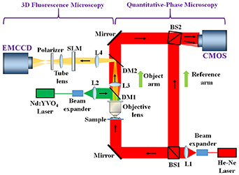
Figure 13. The schematic of the multimodal imaging system.
Download figure:
Standard image High-resolution imageFigure 14 shows the results of the simultaneous observation of fluorescence and QPI of the microsphere fluorescent beads (of size ∼10–14 µm). First, the fluorescent beads are imaged on the image sensor, as shown in figure 14(a). The fluorescent beads are moved in the z-direction by 80 µm and a digital hologram, as shown in figure 14(b), is recorded by displaying a lens function (focal length = 800 mm) and diffraction grating (grating period = 300 µm) onto the SLM. The object information is retrieved from the recorded hologram, as shown in figure 14(c). QPM, implemented by off-axis digital HM with a transmission-type configuration, is realized to retrieve quantitative-phase information of the same fluorescent beads. In QPM, two digital holograms are recorded corresponding to the presence and absence of the fluorescent beads. Figures 14(d)–(h) show the experimentally obtained results of the QPM. Figures 14(d)–(f) show the recorded digital phase hologram, the retrieved intensity, and the wrapped phase image of the fluorescent beads correspond to figure 14(a). Figure 14(g) shows the unwrapped phase map of the fluorescent beads and figure 14(h) depicts the 3D unwrapped phase map of a selected fluorescent bead. The proposed multimodal imaging system may resolve several biological issues and measure various biophysical cell parameters in real-time through a single investigation. In the future, there is a need to refine some more compact and efficient multimodal systems capable of providing valuable information with further superior spatiotemporal resolution and high molecular specificity by fully exploiting these techniques.
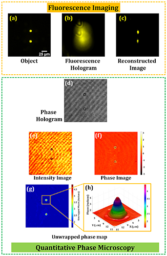
Figure 14. The experimentally obtained results of the multimodal system.
Download figure:
Standard image High-resolution imageAdvances in science and technology to meet challenges
The optics laboratories could be exploited in biological laboratories by resolving various challenges and issues associated with these multimodal systems. For example, in biological applications, the sensitivity of recording hologram is one of the critical issues. Inherently, holography requires two light waves with enough beam size to obtain the interference pattern. This results in a decrease in the detected intensity at each pixel. To avoid the phototoxicity, there is the limitation of the fluorescence light from the sample. A high-sensitive image sensor such as an electron-multiplying CCD or photon-counting based DH technique is available.
DH can reconstruct cross-sectional images by changing the propagation distance from the image sensor plane. For 3D tomographic imaging, the separation along the propagation direction is a key factor. One solution is the compressive sensing [149]. In the biological sample, the fluorescence light sources are sparsely distributed. Therefore, the compressive sensing technique is effective to improve the reconstruction distribution along the depth direction. Another solution is deep learning neural networks [150]. By training ideal 3D reconstruction from the observed data, the neural network is available to improve the reconstructed 3D distributions. The efficiency of such a multimodality imaging approach may significantly be enhanced by exploring the recent advances occurred surrounding DH and image processing.
Concluding remarks
DH is a promising technique to realize the multimodal 3D imaging by using the multiplexed recording of the holograms. Especially for biological applications, simultaneous recording of 3D phase and fluorescence distributions gives a powerful tool for the dynamic observation of the cellular network, for optogenetics [148], and characterization of some unique biophysical processes. In optogenetics, 3D observation and 3D optical stimulation of cellular network will give the high-level technology in the manipulation of brain function. These systems play an important role in understanding many biophysical processes occurring in the biological specimens and therefore could be helpful in the diagnosis and treatment of various diseases.
Acknowledgments
This work has been supported by JSPS KAKENHI (18H03888) and JST CREST Grant No. JPMJCR1755, Japan.
10. EUV and SXR holography and tomography with compact short wavelength sources
Przemysław W Wachulak
Military University of Technology, Poland
Status
The discovery and developments of coherent imaging techniques, such as holography and optical coherence tomography (OCT) in the visible and NIR range of electromagnetic spectrum, undoubtedly, initiated the advancements in various fields of science. Holography, since its discovery by Gabor in 1948 [151], allowed recording both amplitude and phase of the electromagnetic wave, which allowed for 3D imaging and numerical refocusing for the first time. It significantly benefited such fields of science as biology, medicine, physics, material science and many other. Moreover, the OCT allowed reaching in-depth information by using partially coherent electromagnetic radiation and probing the internal structure of the investigated object with unparalleled resolution, in such 'difficult' objects as eyes. Such an achievement before inventing the OCT was impossible without damaging the object.
However, as the wavelength of visible radiation is between 400–700 nm, it limits the possibility to go much beyond 200 nm spatial resolution in classical, diffraction limited systems. For NIR systems the diffraction limited axial resolution in the OCT is also of the order of ∼1–2 μm. The spatial resolution, typically assessed using Rayleigh criterion [153], can be expressed as:
where λ is the illumination wavelength, NA is the numerical aperture of the objective or maximum half-angle subtended by the marginal rays during the recording, in the case of holography. The a is a constant from 0.34 to 1 [154]. Additionally, the axial resolution δc in the OCT is typically related to the longitudinal coherence len2gth lc,

where is the wavelength emission range (bandwidth), IRB—inverse relative bandwidth. For typical broadband NIR source of λ = 1 μm and Δλ = 400 nm (IRB = 2.5) the lc = 2.5μm. Such value in the micrometer spatial scale is insufficient for many applications. Moreover, many materials exhibit very low transmission in the VIS/NIR spectral ranges. It makes difficult to scatter the electromagnetic field out of refractive index discontinuities in the investigated samples.
Thus, the easiest way to improve, both, spatial resolution in holography and axial resolution in OCT is to employ shorter wavelength, from EUV (λ = 10–120 nm) and SXR (λ = 0.1–10 nm) ranges. A few orders of magnitude shorter wavelength allows to decrease  and
and  from a micrometer range down to nanometers. Another advantage, especially in the EUV/SXR holography, is the lack of optics, which is still of low efficiency and throughput, even after decades of development.
Current and future challenges
Still, however, there are significant issues and difficulties to be overcome, before such methods will find widespread applications in various fields of science. It is because, typically, holography and OCT in the EUV/SXR spectral region, often called XCT (x-ray coherence tomography, is performed with large-scale sources, i.e. synchrotrons for the XCT [155] or table-top (but a few large optical tables in size) sources such as high order harmonic generation sources, driven by a fs-class lasers in case of holography [156]. Such complicated and expensive sources prohibit the widespread of these techniques. Moreover, both techniques require high photon flux, possible using synchrotrons or free electron lasers.
In case of EUV/SXR holography, typically one-shot (a single light pulse) exposure is preferable for time-resolved imaging, while in case of the XCT, low reflectivity of the investigated samples at nearly normal angle (in relation to the surface of the sample), of the order of ∼0.1% [157] makes necessary for the source to have high photon yield.
Thus, the best combination for those types of coherent imaging experiments, at least for now, seems to be the use of compact high flux coherent and partially coherent EUV and SXR sources.
Advances in science and technology to meet challenges
One of such sources might be a capillary discharge EUV laser [158], (λ = 46.9 nm), employed for diffraction limited EUV Gabor holography [152] and laser plasma Kr/He SXR source, (λ = 2.2–5.5 nm), based on a double stream gas puff target [159],, employed for the XCT experiments [160]. Such sources are both compact and easy to use, which will allow for the widespread of holographic and XCT techniques in the various fields of science, such as biology, material science, and nanotechnology.
In the first experiment, a Gabor holography of carbon nanotubes (CNTs) was performed. A sample was composed of 50–80 nm in diameter and 10–20 μm in length CNTs, placed on a 100 nm thick silicon membrane. The membrane acts as a support to position the object at approximately 2.6 μm away from a 120 nm thick layer of poly-methyl methacrylate (PMMA) photoresist. The CNTs were illuminated by a λ = 46.9 nm Ne-like Ar EUV laser. The hologram (figure 15, left) was recorded as a relief modulation in the photoresist surface by the EUV exposure. The developed photoresist (MIBK:IPA 1:3) surface was mapped with an AFM to generate digitized hologram, with the effective value to NA = 0.88. The hologram was reconstructed by numerically (figure 15, right) simulating the illumination with an EUV readout wave using a Fresnel propagator. A spatial resolution of 45.8±/−1.9 nm was achieved, comparable to λ = 46.9 nm. This method allows for diffraction limited EUV imaging, moreover, in the surface of the photoresist, a much larger area than digitized by AFM, might be stored. This allows in principle Gigapixel images to be recorded in this scheme at EUV/SXR wavelengths. As an example, a hologram 2 × 2 mm2 in size, having a moderate resolution of 50 nm is equivalent to a 1.6 Gigapixel image of the sample. Of course, it has to be digitized later, but the information about the investigated object is already recorded and available. The EUV Gabor holography with photoresist is ultimately limited by the resolution of the photoresist, which for PMMA is ∼10 nm.

Figure 15. An example of the diffraction limited Gabor EUV holography of carbon nanotubes performed with capillary discharge EUV laser, λ = 46.9 nm. Reprinted with permission from [152] © The Optical Society.
Download figure:
Standard image High-resolution imageA second example is the SXR XCT experiment, performed with Kr/He double stream gas puff target source. It emits radiation the wavelength range from λ = 2.2 nm to 5.5 nm with the emission bandwidth of Δλ ∼ 2 nm, which results in the coherence length lc from equation (5) in range of 2–12.5 nm. Such radiation, illuminating a 10 nm period Mo/Si structure, with 6 nm of Si and 4 nm of Mo, 40 periods in total on top of SiO2 substrate, due to interference between radiation reflected from the top layer and subsequent layers, allowed only particular wavelengths to be present in the reflectivity spectrum R(λ). From the spectrum, the axial locations of discontinuities in the refraction index were calculated (figure 16, bottom plots). The calculated locations of the Mo/Si layers are in very good agreement with the theory. Such an approach allows for an axial (depth) resolution of 2 nm. This value is the width of the discontinuity of the index of refraction, but its position has a much better accuracy of less than 1 nm.

Figure 16. An example of the SXR XCT experiment performed on 10 nm period Mo/Si multilayers with Kr/He laser-plasma source, λ = 2.2–5.5 nm.
Download figure:
Standard image High-resolution imageIn such SXR XCT no optics are required, the samples, however, typically exhibit a reflectivity of the order of 10–3 in the SXR range at close to normal surface angles, for which a reflectivity spectrum acquisition might be challenging.
Concluding remarks
An employment of the EUV and SXR short wavelength compact sources allow overcoming current limitations related to the spatial and axial resolutions in holography and OCT, respectively, related to the use of much longer wavelengths. To allow for time-resolved studies, however, single-shot exposures are necessary. This puts stringent requirements on the coherence and high photon flux EUV/SXR sources, as well as their compactness, which is required for the widespread of those coherent imaging methods in a variety of fields of sciences, such as biology, material science, and nanotechnology. Moreover, the EUV/SXR radiation can penetrate only from 100 nm up to 10 μm thick samples, repsectively. Such strong absorption requires a careful consideration of the EUV/SXR photon flux, especially while imaging biological samples. It is due to the fact that the EUV/SXR photons carry 10–1000 eV energy and can easily ionize atoms, break chemical bonds (i.e. polymer chain scission) or othervise affect the fragile biological structures [161]. Thus, further development of the sources and the optimization of these techniques has to be continued.
Acknowledgments
This work is supported by the National Science Centre, Opus programme, Grant Agreement Nos.:
- UMO-2015/17/B/ST7/03718,
- UMO-2015/19/B/ST3/00435,
- 2016/23/G/ST2/04319 (Beethoven program number).
We acknowledge Professor Mario C Marconi from Colorado State University and Professor Henryk Fiedorowicz from the Military University of Technology, for their contributions to the holography and XCT work examples, presented herein.
11. Holographic wavefront sensors
Alina V Gorelaya1, Alexander A Sevryugin1, Egor V Shalymov1 and Vladimir Yu Venediktov1,2
1 St.-Petersburg Electrotechnical University, Russia
2 St.-Petersburg State University, Russia
Status
Wavefront sensors (WFS) are the devices that measure the deviation of the wavefront of optical radiation from a plane or sphere. Today, they are widely used in adaptive optics (AO), astronomy, laser technology, ophthalmology and many other fields. For today there are available only the so-called zonal WFS, first of all the Shack–Hartmann sensor and, more rarely, other types like a sensor of curvature or the pyramidal one. Zonal WFS first determine the local parameters of the wavefront, such as local slope or curvature of its segment, and then, using the cumbersome calculations, reconstructs the shape of the overall wavefront. This severely tantalizes the performance of this type of system. In some cases, especially for atmospheric optics applications, a WFS with a data refresh rate of 1 kHz or more is necessary. The use of optimized processing algorithms and high-performance computing systems allows to create AO systems operating at a frequency of several kHz. However, in the tasks that require high speed AO systems and/or do not allow the use of large and expensive computing systems, actual is the use of modal WFS. They give information about the wavefront in the form of only a few dozens of numbers—the amplitudes of the Zernike modes or adaptive mirrors modes. Thus, the signal from them can directly control the shape of adaptive mirrors without additional processing. Particularly relevant is the use of modal WFS in problems requiring evaluation of only the first few modes of Zernike, for example, in ophthalmology. The only concept of the modal WFS, which is known for today, is the one based on holography.
The first publication devoted to holographic WFS was the work of Neil et al [162]. In their work, they theoretically considered a new version of the principle of construction of modal sensors. Initially, prior to the use of holograms, modal WFS were exotic bulky optical circuits and could only measure a limited number of Zernike modes of the incoming wavefront. The authors proposed the use of holographic filtering of the input wavefront, which allowed to distinguish Zernike modes in the form of a system of spots in the plane of the photodetector. (figure 17(a)). The amplitudes of the Zernike modes present in the input wavefront are proportional to the difference in the intensities of the pairs of symmetric spots. For holographic filtering, they proposed using either several separate diffraction elements (holograms)—each for filtering one of the Zernike modes, or one multiplexed in time or spatially (multiplex hologram) element. The new type of sensor is called holographic WFS. Neil et al first demonstrated in practice the work of the AO system using holographic WFS [163]. One of the holograms is recorded as the interference pattern of the wave with the front, deformed according to the selected Zernike polynomial and the spherical wave, converging to some point A. The second hologram corresponds to the interference pattern of the wave with the inverted value of the same Zernike polynomial and the spherical wave, converging to some other point B. Photodetectors are mounted in points A and B, and then the analyzed wavefront reconstructs the duplex. Depending on the amplitude of the Zernike mode, the signal from the photodetector in point A exceeds that in B or vice versa. If this Zernike mode is absent in the wavefront, the signals from both detectors are equal. Later these researches were continued by several scientific groups, in particular, by the team of G Andersen [164, 165].

Figure 17. Modal holographic WFS (a) and AO system with zonal holographic WFS (b).
Download figure:
Standard image High-resolution imageAndersen developed the idea of holographic WFS and had also adapted it to work in the AO system with zonal corrector (figure 17(b)). In this case, a hologram consisting of several dozens of separately recorded areas is used. Two superimposed holograms corresponding to two states of the zonal corrector—the maximum positive and negative shifts induced by one of the corrector drives are recorded for each section. When a distorted wavefront enters the AO system, the difference in the intensities of pairs of symmetric spots is proportional to the signal to be applied to the corresponding drives of the zonal corrector to eliminate wavefront aberrations. This allows to implement the AO system without the use of computer technology.
Current and future challenges
The use of several separate channels with holograms filtering only one of the Zernike modes in the WFS is impractical, since in this case the sensor becomes bulky and the intensity of the radiation incident on each of the holographic elements decreases (inversely proportional to the square of the number of channels). Therefore, the desire of researchers to use WFS with multiplex holograms [162–170] is justified.
Despite the advantages of using multiplex holograms, cross-modulation noise occurs when they filter Zernike modes [162, 166]. It is clear that with an increase in the number of measured Zernike modes, the number of superimposed holograms that make up the filtering multiplex hologram increases proportionally, and, as a result, the cross-modulation noise increases.
It should be noted that using the principle of operation of the holographic WFS proposed by Andersen [165], it is possible to minimize cross-modulation noise, since in this case each of the sections of the filtering hologram consists of only two superimposed holograms. However, such holographic WFS measures the wave front in the amplitudes of the zonal corrector modes that do not correspond directly to the aberration modes. This solution is suitable only for AO systems with zonal corrector. The effect of cross-modulation noise can be reduced by optimizing the design of the filter hologram, the size of apertures and the position of photodetectors and the number of recorded Zernike modes [167, 168].
The transition to temporal multiplexing of holograms allows to completely solve the problem of the cross-modulation noise. In this case, holograms filtering only one of the Zernike modes are alternately formed on the same optical element [162]. To create such dynamic holograms, spatial phase LC modulators can be used [171], but their technical characteristics (pixel size, switching time, etc) do not allow to implement high-quality high-speed holographic WFS on the basis of existing samples. The negative effect of the use of time multiplexing is also a decrease in the speed of the holographic WFS in proportion to the number of measured Zernike modes.
The team of Gladysz has demonstrated one more approach to the solution of the cross-noise problem [169]. The have used the filters, comprised by mosaic of numerous segments, belonging to holograms, responsible for various Zernike modes. In this case there is no overlapping of holograms, but other problems arise due to diffraction on small separate subapertures.
Another promising approach to the construction of WFS is the use of Fourier holography with the diffuse scattered beams [170, 172]. In this case, the WFS contains a hologram consisting of separate sections, each of which contains Fourier holograms filtering one of the Zernike modes. Let the hologram is recorded by the focused radiation, and one of the recording beams, beam A, which is bearing some phase information (e.g. its wavefront corresponds to Zernike polynomial with definite amplitude), is scattered before record by some diffuse scattering surface with some definite parameters (depth and transverse size of scattering roughness), and the second recording wave B does not have diffuse component; it can be, for instance, the plane wave, propagating to some definite direction Then let us reconstruct the recorded Fourier-hologram by the beam A' with the same phase distribution, scattered by the same diffuse scattering surface. In this case the diffraction of the beam A' on the hologram will reconstruct the same wave B with some accompanying diffuse noise (halo). This noise can be easily removed by spatial filtration. For the neighboring segment of hologram the angle of incidence of the object wave changes and the sign of the amplitude of the Zernike mode changes to the opposite. Similarly, the remaining portions of the hologram are recorded for other Zernike modes. When measuring, the input wavefront is sent through the same diffuser and focused onto the overall holographic matrix. The diffuse scattered beam illuminates all elementary holograms simultaneously, and each of them provides the data for the corresponding mode. Theoretically, this should allow to get rid of cross-modulation noise [172]. It is worth noting that the use of the diffuser leads to the appearance of characteristic noise, but it is easy to reduce it by spatial filtration. Recently this approach was confirmed in the experiment.
Advances in science and technology to meet challenges
In the near future the development of holographic WFS is associated with different ways of optimizing their design with respect to the specific applications. Improvement of spatial phase LC modulators, in particular, increasing the frame rate to several tens of kHz, reducing the pixel size, etc, should give a serious impetus to the development of holographic WFS, especially WFS with time multiplexing.
Concluding remarks
Already today holographic WFS allow to implement OA systems with zonal corrector without the use of computer technology. In the future, it will be possible to create on their basis other types of AO systems, which will reduce the size and cost and improve the performance of the latter to MHz range and above.
Acknowledgments
Vladimir Venediktov is grateful for the financial support of this work, which was provided by the Ministry of Education and Science of the Russian Federation (assignment 8.5599.2017/6.7).
12. Holographic microscopy goes incoherent
Radim Chmelik
CEITEC Brno University of Technology, Czech Republic
Status
Holographic microscopy (HM) appears a notable QPI technique among others such as wavefront sensing, ptychography, phase tomography, spatial light interference microscopy and related techniques [173, 174]. The QPI context and impact clearly show the future possibilities of HM and implies advances, which are desirable for the best utilization of its still latent potential.
QPI is becoming increasingly important in biomedicine [173, 174]. Like Zernike phase contrast and Nomarski DIC QPI shows the shape and position of the living cells with high contrast non-invasively without labeling. In addition, QPI measures the phase shift in each image point that is proportional to the mass density of non-aqueous material in live cells [175]. Rapid quantitative evaluation of cell growth and translocation can be complemented with an exact cell segmentation and protrusion/retraction analysis when sufficient accuracy of phase measurement is achieved. In this way, very detailed quantitative assessment of cell behavior can be accomplished on completely label-free basis, in long-term time-lapse experiments with tissue culture. In addition to its label-free substantial advantage, QPI values are not distorted by quenching possibly associated with quantitation of fluorescence imaging. Using QPI approach, behavior of cells and their reactions to external stimuli including therapeutics can be evaluated in a quantitative way thus establishing a completely new cytometry approach [174]. Another emerging significant application areas may lie outside the field of life sciences. For example, it has been shown that QPI can also be used to measure phase effects produced by meta-surfaces with high resolution [176].
Dennis Gabor holography was connected with the development of microscopy from the very beginning. It was proposed as a way to increase the magnification of electron microscope. The Gabor idea was further developed in the field of light optics namely by Leith and Upatnieks who discovered an off-axis holographic record optically separating spurious conjugate and zero-order images. The first off-axis holographic microscope [177], which had been created by attaching a reference arm to an ordinary light microscope, provided the reconstructed intensity of a recorded wave both in the image plane and out of it. Due to the absence of computerized processing of a hologram the image phase was not accessible. For this reason, rapid development of HM based on off-axis holography did not start until the end of the nineties when digital image recording and reconstruction became commonly available. As only one off-axis hologram record is sufficient for the complete reconstruction of the image amplitude and phase, which is usually performed by the fast Fourier transform methods, the conditions of observation with off-axis HM correspond to those of common light microscopy with real-time full-field imaging.
Current and future challenges
Gabor in-line holographic set-up is easy to implement but not suitable for QPI use, because the overlap of the image with the conjugate and zero-order ones reduces accuracy of the phase measurement. In-line configuration can be retained if a phase-shifting technique is applied. This requires to separate reference and signal beams. Such a set-up can be adjusted to the off-axis approach that we will continue to consider. The off-axis record is convenient for the fast-phenomena QPI, because it does not limit the imaging frame rate by a scanning system. It requires higher sampling density in the spatial domain, which is addressed by ever-increasing camera chips.
In the case of off-axis approach, the cause of the reduction of QPI accuracy is the high coherence of illumination required by conventional off-axis holographic systems. Coherent illumination brings about strong coherence noise [179] and unwanted interference and diffraction phenomena in the reconstructed image (compare figures 18(a) and (b)). These spurious effects can be suppressed by averaging images recorded with slightly different illumination parameters, such as a source position and wavelength. The most effective averaging is certainly the use of parallel imaging channels with maximum density, which is just imaging with an incoherent source. Moreover, the incoherent illumination gets back the resolving power of HM to the wide-field microscopy standard [180] (compare figures 18(c) and (d)).

Figure 18. Improvement in HM image quality and resolution due to the reduction of light coherence illustrated by the coherence-controlled holographic microscope (see the text) observation with (a), (c) coherent (laser) illumination, (b), (d) incoherent (halogen lamp) illumination. (a), (b) QPI of live cells (field size 95 µm × 95 µm, pseudocolor look-up table denominates increasing mass density of non-aqueous cell material), (c), (d) amplitude images of a resolution-test target (field size 28 µm × 28 µm). Reprinted with permission from [178] © The Optical Society. Objective lens 20x/NA = 0.50 used.
Download figure:
Standard image High-resolution imageHowever, the key benefit of incoherent illumination in HM is the coherence-gating effect, which allows to block the light scattered by the unwanted parts of a specimen. Caulfield pointed out this possibility for the first time in 1968 using the temporally incoherent light for a holographic record. Then the idea was elaborated by Emmet Leith in the early 1990s [180]. The effect occurs due to a significant reduction of the coherence volume in the region of a hologram record. As a result, the light scattered outside the object plane of holographic microscope can be prevented from contributing to the hologram formation and therefore also to the reconstructed image signal. In this way, HM and thus also QPI through scattering media was made possible (see figure 19), while the effect of optical sectioning fully comparable to confocal imaging can be achieved in reflected light [180]. Moreover, QPI of objects in scattering media can be obtained by separating not only the ballistic (and snake-like) photons (figure 19(c)), but also subgroups of multiply scattered photons, while the complex amplitudes of images obtained by various groups of photons can be superimposed (figure 19(d)) [181]. Creation of the coherence-gate effect requires holographic microscope with a reference arm separated from an object (signal) one.

Figure 19. QPI of a phase resolution-test target (a) observed by the coherence-controlled holographic microscope (see the text) through scattering layer (one-side etched glass plate) using illumination of spatially (b) high coherence (condenser lens NA = 0.05), (c), (d) low coherence (condenser lens NA = 0.30). Quantitative phase images were formed by (c) ballistic and snake-like photons, (d) multiply scattered photons only (complex-amplitude superposition of 110 reconstructed images). Halogen-lamp illumination with filter 650 nm/10 nm and objective lens 20x/NA = 0.50 used. Reproduced with permission from [181].
Download figure:
Standard image High-resolution imageAdvances in science and technology to meet challenges
As can be seen from the previous reasoning, the main technological challenge is the implementation of an off-axis holographic microscope with the separate reference arm accepting the highly desirable both spatially and temporally incoherent illumination.
A fully uncompromising solution was proposed by Leith and Upatnieks as the concept of incoherent holography based on the grating achromatic-fringe interferometer [182]. The interference pattern of an image-plane hologram is formed by imaging a diffraction grating used as a beam splitter of the interferometer. The invariance of the pattern with respect to the source position and wavelength is then limited by the aberrations of the optical system only.
This concept can be referred to as the holographic incoherent QPI (hiQPI), or—after the author of key ideas—the Leith microscopy. One of its possible implementations is known as the coherence-controlled holographic microscope [173, 174, 178], commercially available as Telight Q-Phase microscope. Relative complexity of this instrument is outweighed by its advantage to work in a wide range of the light coherence ranging from coherent to both spatially and temporally incoherent illumination. This microscope was utilized in experiments documented by figures 18 and 19 and many other experiments in live-cell biology.
Concluding remarks
We proved that hiQPI is robust enough technique capable of live-cells QPI in 2D and 3D conditions. Inherent coherence gate suppresses the image contribution of light scattered outside of the microscope object plane and thereby restricts the observed area along the z-axis. This produces potential for 3D and in turbid-media imaging, which is of particular importance in biomedical imaging.
Particular attention is to be paid to QPI-related issues. Although the coherence-gate prevents the light scattered outside of the object plane from contributing to the output signal it cannot prevent surrounding medium to affect the phase shift of the light scattered in focus. Then the broader problem is to what extent QPI of a focused section can be preserved from the influence of an object surroundings in turbid-media or 3D observations.
These questions are offered for further intensive research as well as novel implementations of hiQPI made more compact by utilizing progressive optical elements.
Acknowledgments
I thank Pavel Veselý and Daniel Zicha from my group for discussions. Our work relevant to this paper was supported by the Czech Science Foundation (project 18-01396S) and the MEYS CR (Large RI Project LM2018129 Czech-BioImaging and project LQ1601 CEITEC 2020). R C is a co-author of patents covering Q-Phase device.
13. Digital polarized holography for life science applications
Maria Antonietta Ferrara and Giuseppe Coppola
ISASI, National Research Council, Italy
Status
Digital holographic imaging (DHI) is a label-free, non-contact, non-invasive and high-resolution method that has widely used in several applications, biological and not, due to its capability to allow, from a single acquired image, a numerical reconstruction both of the phase and amplitude maps of the optical wavefront emerging by the sample. Therefore, a 3D quantitative image of the sample can be automatically produced by numerical refocusing of a 2D image at different object planes [183]. In particular, in cells analysis, the phase map is related to the 3D refractive index distribution of biological specimens, that provides information about the density of cells [175], its metabolism [184] and/or tumorous transformations [185]. Moreover, 3D sectional imaging has been demonstrated combining DHI with tomography approaches [186].
On the other hand, the order of molecular architecture can induce a dependence of the refractive index on the polarization and propagation direction of the light. In fact, the presence of filament arrays and/or membranes (made of a lipid bilayer that exhibits some degree of orientation) that are included in organelles and cells, induces an anisotropy of refractive index (birefringence). Thus, if a polarized light is used to illuminate cells and tissue, their birefringence can alter the polarization state of the light. The study of this modification has been used to identify the molecular order, follow events, diagnose diseases since the pioneering works reviewed by Wolman [187]. However, these techniques require the acquisition of several images to determine the birefringence of the studied sample. The possibility to use a holographic approach for polarization imaging gives the possibility to evaluate the birefringence pattern from a single image acquisition [188, 189]. This can be made through a slight modification of the standard DHI setup [188, 189]. Thus, holograms that contain both information about the polarization state and about morphological parameters, such as area and volume of the object, can be recorded, allowing fast and simple diagnostic.
Current and future challenges
Polarized DHI (P-DHI) can be applied to the study of anisotropic biological specimens in order to characterize both their birefringence pattern and their morphological parameters, such as area and volume, enabling to distinguish among different states of the sample and to allow diagnostic [188–190]. A configuration of the experimental set-up useful to record holograms with different polarizations is shown in figure 20. Basically, it consists in two Mach-Zender interferometers obtained by splitting the reference signal into two orthogonally linearly polarized reference waves (R1 and R2) by a polarized beam splitter (PBS), while the object wave (Obj) is linearly polarized by a polarizer (P1) and a quarter-wave plate (QWP1) [189]. Thus, the Obj field interferes with both R1 and R2 waves by a beam splitter (BS1), giving rise to two different sets of fringe patterns (see figure 21). Moreover, the holographic approach allows removing the spurious anisotropy due to optical components (lenses, mirrors, objective) in order to evaluate only the birefringent contribution of the specimen under test. So, P-DHI has the unique feature of a full characterization of morphological and birefringent properties, in a label-free way, from a single image acquisition.

Figure 20. Polarized digital holographic microscope: experimental setup. Abbreviations: M, mirrors; L: lens; BS, beam splitter; PBS, polarized beam spitter; QWP, quarter-wave plate; HWP, half-wave plate; P, polarizer.
Download figure:
Standard image High-resolution image
Figure 21. Polarized digital hologram. (a) Quantitative morphology information obtained by the retrieved phase map; (b) 4D tracking system could be used to track the cell motility; (c) birefringence pattern based on P-DHI: properties significantly different in relation to acrosome state can be observed.
Download figure:
Standard image High-resolution imageAn example of results obtained applying P-DHI is illustrated in figure 21. In this specific case, sperm cells were characterized. Morphological information retrieved by the reconstructed phase map, allows to highlight any defects (figure 21(a)), while 4D particle tracking performed in live specimen can provide a better understanding of the sperm behaviour and its relation with male infertility (figure 21(b)). Finally, the birefringence pattern reported in figure 21(c) gives information about the acrosome status allowing to distinguish between non-reacted spermatozoa with an intact acrosome, that are totally birefringent, and those that are reacted, in which birefringence occurs only in the post-acrosomal region [191]. The whole of these parameters are of clinical relevance especially for the evaluation of the healthy state of the semen and for the selection of the spermatozoon to be used for intracytoplasmic sperm injection (ICSI).
This enables the study of rearranging molecular structures, nerve activity, shock wave propagation, and other fast-moving events. Therefore, the polarization light observations in terms of cellular structure and/or activity can be highlighted and univocally interpreted. In this context, the possibility of fast acquisitions combined with a tomographic approach can open up new possibilities for studying molecular architecture and its dynamics reassembling for unstained cells. Thus, P-DHI could be a valid diagnostic tool for different applications; such as sperm selection for ICSI [191], diagnosis of sickle cell anaemia and malaria [192], diagnosis of progressive neurodegenerative disorders (Alzheimer's, Parkinson's, Huntington's, transmissible spongiform encephalopathies) [193, 194].
The main limitation of the holographic approach is related to the possibility to retrieve a refractive index distribution that can be related to the morphology (isotropic samples) and/or orientation of molecular architecture (birefringent samples), but no information about the biochemical nature of the biological material is provided. Raman spectroscopy, on the other hand, is a label-free technique useful to identity chemical building blocks. So, a combination of P-DHI with a Raman spectroscopy could be a powerful tool to identify the structural and molecular specificity of a biological specimen [190].
Advances in science and technology to meet challenges
The challenge to dynamically characterize the molecular architecture of cells by means of a polarized holographic approach, although there have already been encouraging results, still require key technological and scientific advancements. Probably the most important is the ability to univocally correlate the birefringence distribution to the cellular architecture. To face this aspect, the possibility to use pulsed laser source, in order to investigate fast events, is extremely important. Moreover, due to the non-homogeneity of the biological specimen, the P-DHI from a single angle of illumination and/or a single wavelength can provide only partial information of the 3D specimen. Thus, a combination of a tomographic and multispectral approach is required in order to carry out an as complete as possible cell characterization. Finally, the full integration with other techniques that allow a correlation between the molecular architecture features and the biochemical ones is hoped. In this respect, Raman spectroscopy, both spontaneous, for a full biochemical characterization [190], and stimulated, for non-scanning chemically selective 3D bio-imaging [195], seems the most promising approach to investigate.
Concluding remarks
The development of P-DHI and experimental studies of birefringence pattern in biological samples have already demonstrated the superior performance and unique characteristics of this approach, revealing the enormous potential to characterize in a single label-free acquisition cells morphology, motility and birefringence for diagnostic. The key features of P-DHI consists essentially in its versatility both to obtain multiple information and to combine with other techniques, which also open up new avenues for a better understanding of some diseases, as well as in the fields of the clinical diagnostic tool.
14. Using PA-LCoS microdisplays for holographic data storage
Andrés Márquez and Augusto Beléndez
University of Alicante, Spain
Status
Since Pieter J van Heerden [196] proposed holographic data storage (HDS) in the 1960s, many efforts have been dedicated to this enterprise. The challenges involved by the necessity of appropriate light sources, SLMs and recording material, among other components and accompanying techniques have made this a very challenging pursuit as reviewed by different authors [15, 88, 197]. Nowadays holographic memories research is focus on write-once read many memories oriented to the application of archival data storage because they meet most of the requirements, such as low bit cost, long-term life, high robustness, fast accessibility, low power consumption and high portability [88, 197]. Demonstration prototypes have been developed but other competing technologies have prevented them to reach the general market. Continuous advances in capacity and data transfer rates might however provide new opportunities for holographic memories in the commercial arena in the future. Two main optical architectures have attracted the attention, which are the more conventional 2-axis scheme [198], which enables various multiplexing methods and facilitates usage of multilevel codification of data pages [199], and on the other hand, collinear or coaxial systems, which might simplify the system structure and enhance robustness [200].
The entry data point for data pages, provided by an SLM [202], is one the relevant elements in the holographic data storage system (HDSS) [15, 88, 197]. They have greatly evolved from the mostly used in the 90 s transmissive liquid crystal displays, and nowadays three main technologies are applied in HDSS. Deformable mirror devices and ferroelectric liquid crystal displays provide very fast frame rates, over the kilohertz, but are limited to binary modulation. On the other hand, nematic LCs in parallel-aligned LCoS (PA-LCoS) microdisplays are slower, tens of hertz, but combine both very high spatial resolution and light efficiency and enable multilevel modulation schemes [201]. For all of these reasons we introduce this novel device as the SLM in our HDSS platform [202, 203], which belongs to the 2-axis architecture category.
Current and future challenges
Many scientific and engineering aspects need to be addressed for HDSS to be viable in the commercial arena as explained by Curtis et al [88]. Impact of ongoing advances in SLM technology, and specifically in PA-LCoS microdisplays needs to be explored.
In the first instance, PA-LCoS can be modelled as variable linear retarders, thus the magnitude of interest is their linear retardance as a function of the applied voltage [201 – 203]. This means that PA-LCoS enable phase-only operation, what makes them ideal for binary or multinary phase-only data pages, which leads to DC term cancellation when recording the Fourier transform of the data page.
Hybrid-ternary modulation (HTM) is another scheme which combines the ease of detection of binary intensity modulated (BIM) pages together with DC term, i.e. zero order, cancellation of phase-only modulation. HTM requires three gray level values, two of them with a high and equal intensity transmission and with a 180° relative phase-shift (ON levels), and a third gray level with a low intensity transmission (OFF level). In [201] we found that PA-LCoS devices do not produce a pure HTM modulation, but they enable an approximate trade-off, which we call pseudo-HTM modulation (pHTM). In figures 22(a) and (b) we show the intensity transmission and the phase-shift as a function of the gray level for one of the possible pHTM configurations obtained in our simulations where the PA-LCoS is between two linear polarizers. We plot the curves taking into account the existence of flicker in the device, where 'PosFluct' and 'NegFluct' express respectively the curves considering the addition and substraction of the flicker to the average retardance of the device. 'NoFluct' considers the situation with no flicker. Vertical dash lines are located at the three gray levels producing the best compromise for the pHTM. Phase-shift difference between the ON values is 206° and intensity contrast is 1:10.

Figure 22. Simulation for pHTM. (a) Intensity transmission; (b) phase-shift. Reproduced with permission from [201].
Download figure:
Standard image High-resolution imageIn the literature dealing with application of PA-LCoS in optics and photonics applications [202], various degradation effects are identified which reduce its performance. These are mainly the flicker in their retardance response, more relevant in digitally addressed devices [201, 202], and that was considered in the plots in figure 22. Then, there are also other degradation phenomena which lead to interpixel cross-talk, which are the anamorphic and frequency dependent effects [202, 203]. Anamorphic and frequency dependent effects may be produced by limitations in the bandwidth of driver electronics, but also by other phenomena such as fringing-field or LC adherence in the transverse direction between neighbouring LC molecules.
We have recently analyzed the effect of the anamorphic and frequency dependent effect in our PA-LCoS data pager [203]. We want to know if it affects significantly our storage capability. To test it we have prepared a set of linear test patterns (bar codes) with different resolutions and with two orientations, vertical and horizontal. We analyze the results for the whole page and also locally dividing it in various zones, as shown in figure 23(a). When comparing the retrieved image in the experimental HDSS with the one originally addressed to the PA-LCoS we produce the histograms with the 1's and 0's in the data page (we consider BIM). Figure 23(b) is an example in which there is a slight overlap, which leads to a non-zero BER. From the analysis we obtained that even though in the case of multilevel phase elements the PA-LCoS has the anamorphic degradation, this is not the case for binary modulation. What is still existent is the frequency dependent effect which obliges to resize the bit in the PA-LCoS to more than 2 × 2 pixels bit−1 to assure a reasonable value of the raw BER (before addition of error correction codes), lower than 10–3.

Figure 23. (a) Zones defined for illumination homogeneity analysis; (b) Histogram of 0's and 1's from a non-processed (no-thresholded) captured image. Reproduced from [203]. CC BY 4.0.
Download figure:
Standard image High-resolution imageAdvances in science and technology to meet challenges
There are many different aspects to be considered in such complex systems as HDSS. Regarding the capabilities of PA-LCoS devices, the recent arrival of ultra-high definition devices with more 10 megapixels resolution is an opportunity to enhance the recording transfer rate and the areal density, since more bits can be displayed per data page. However, the small pixel size, less than 4 µm, enhances the interpixel cross-talk effects through the fringing field. Therefore, there must be a continuing assessment of the influence this might have on the fidelity of the data pages and what is the smaller bit size, in terms of number of pixels per bit, to assure the necessary BER.
Furthermore, there is a clear interest in increasing the code rate, to increase recording capacity, and to enhance the SNR, which results in higher read/write transfer rates. The introduction of multilevel codification of the data pages, i.e. incorporation of coherent data channels [88] is one of the strategies here. This is analogous to the coherent modulation codes used nowadays in modern fiber optics communication systems. To this goal, PA-LCoS are the SLMs of choice. This is something being analyzed both in 2-axis architectures [199] and in the collinear one [200].
We note that all these analysis need also to be done in conjunction with the holographic recording material to reproduce the real working conditions. In this sense, we have used our in-house produced PVA/AA photopolymer, which combines good optical properties and the ease of fabrication with different layer thicknesses [201, 203].
Concluding remarks
Issues related to the data pager in HDSS have been analyzed. Specifically, PA-LCoS microdisplay have been considered, a very versatile SLM enabling the possibility of multilevel codification schemes. From our research in this field, we have shown that every technological enhancement in these devices needs to be analyzed in its specific impact onto holographic storage applications. Reduction in pixel size and introduction of digitally addressed devices have an impact in the interpixel cross-talk, flicker, and in the bits size in the data page (number of pixels per bit).
Acknowledgments
Funded by Ministerio de Ciencia e Innovación (Spain), project FIS2017-82919-R (MINECO/AEI/FEDER, UE); by Generalitat Valenciana (Spain), GV/2019/021; and Universidad de Alicante (Spain), project GRE17.
15. Playing the piano with the brain: holographic imaging and manipulation of neural activity
Weijian Yang1 and Rafael Yuste2,3
1 University of California at Davis, Davis, CA, United States of America
2 Neurotechnology Center, Columbia University, New York, NY, United States of America
3 Donostia International Physics Center, DIPC, Paseo Manuel de, Lardizábal 5, 20018 San Sebastian, Spain
Status
Optical microscopy is one of the most powerful tools in biology. The ability to visualize living structures and events over a wide range of scales has led to fundamental discoveries. At the same time, there are limitations which need to be overcome for even more effective interrogation of living tissues. For example, in conventional microscopes, the sample is either illuminated simultaneously across the entire imaging field (wide-field illumination) or sequentially, pixel by pixel (point-scanning illumination). The wide-field approach can image at high speed as it captures a two-dimensional image at once with a camera, but it suffers from pixel crosstalk generated by light scattering. In point-scanning approach, a single pixel detector captures the fluorescent signals and builds an image, pixel by pixel; when using two-photon excitation, it greatly diminishes the crosstalk by light scattering. But, while suited to image deep in scattering tissue, as a point scanning method, two-photon microscopy has slow imaging speed.
Exploring methods between these two illumination patterns could add extra freedom in microscope design and help overcome some of the fundamental limits of conventional microscopes. One example of such methods is holographic microscopy using spatial light light modulators (SLMs), where arbitrary illumination patterns can be delivered to the sample, making computer-generated holograms (figure 24(a)). SLMs have enabled new functionalities in microscopy, such as fast 3D imaging. Furthermore, holographic microscopy can be used not only to 'read' information from the sample, but also to 'write' information, such as through photostimulation, into the sample. While holographic microscopy was used for optical tweezer [204, 205] more than 20 years ago, the last 10 years have witnessed its growing applications in neuroscience [206–209]. Many designs have been made specifically to image or manipulate neural activity with higher spatiotemporal resolution in 3D, using two-photon excitation.

Figure 24. (a) Generation of a 3D image pattern through computer generated holography. f, focal length of the lens. Reprinted from [209], Copyright (2018), with permission from Elsevier. (b) 'Playing the piano' with neural circuits: simultaneous two-photon volumetric calcium imaging and two-photon 3D holographic patterned photostimulation in mouse cortex. Reproduced with permission from [213].
Download figure:
Standard image High-resolution imageHolographic imaging of neural activity. Neural activity can be optically reported by activity-dependent fluorescence signals from calcium or voltage indicators in the neurons. For a high SNR, two-photon excitation is desirable, particularly for in vivo applications. Conventional two-photon microscopes use sequential point illumination and are thus slow. Using an SLM, the laser beam can be divided into multiple beamlets, each of which targets a specific neuron [207, 208], and a camera can be used to capture the signal.
The hologram essentially multiplexes the laser, significantly increasing imaging speed. Such selective illumination also reduces phototoxicity. A strength of this method further lies on its fast 3D imaging capability. The computer generated hologram can project beamlets over a group of neurons (>100) distributed in 3D. Using a cubic phase plate at the detection path, signals from neurons at different depths can stay in focus on the camera and be simultaneously imaged [210].
Holographic photostimulation of neural activity. Using holographic patterning, neural activity of designated cells or neural processes can be simultaneously activated or inhibited in 3D with high spatial specificity through optochemistry [206, 207] or optogenetics [211]. Depending on the dynamics of the actuators, laser power budget and the required spatiotemporal resolution, holograms can be combined with other techniques, such as galvanometer scanning or temporal focusing (with two-photon light), to deliver different types of photostimulation patterns to the sample [209]. Using two-photon excitation, holographic photostimulation enables precise mapping of the connectivity or function of neural circuits. In particular, when pairing it with two-photon imaging, neural activity can be simultaneously recorded and manipulated with single-cell precision in vivo [212, 213] (figure 24(b)). Such an all-optical approach, as if one were 'playing the piano' with the neurons, provides a powerful tool to study neural circuits in vivo.
Current and future challenges
For both imaging or photostimulation, the goal is to deliver light to a territory as large and as deep as possible, with a spatiotemporal resolution as high as possible, while maintaining optimal SNR. While the integration of holographic patterning into modern microscopes has largely advanced this goal, there are still many challenges that need to be solved.
Firstly, the essence of holographic imaging is to multiplex the laser to probe many regions of interest simultaneously. The above-mentioned approaches use cameras to detect and spatially demultiplex the signal. But in scattering tissues, pixel crosstalk between different excited sources could strongly degrade the signal. Crosstalk naturally increases with a higher degree of multiplexing. So how to maximize the multiplexing (thus the imaging throughput) while being able to reconstruct the signal with high fidelity poses a challenge.
Secondly, in holographic photostimulation experiments, as the number of simultaneously targeted neurons increases, higher laser power is required, which could impose a heavy heat load on the brain. Furthermore, off-target photostimulation could happen, which effectively reduces spatial resolution.
Finally, one of the goals in neuroscience is to understand how animal behavior is generated from neural activity. All-optical piano experiments, where neural activity can be simultaneously recorded and manipulated, appear ideal for these studies. This requires a closed loop across recording and manipulation of neural activity, and observation of animal behavior. This needs development of both hardware and software that can seamlessly work together at high speed [214]. For all-optical experiments, it is also necessary to increase the co-expression level of activity reporters (e.g. calcium indicators) and actuators (e.g. opsins) in the same neuronal population, and further separate their excitation spectrum to minimize the crosstalk between imaging and photostimulation.
Advances in science and technology to meet challenges
Joint innovations across multiple disciplines in engineering and statistics could address some of the above challenges, and enhance the performance and capability of holographic illumination microscopy for brain research.
We recently developed a multiplane imaging system where multiple beamlets scan the sample at different depths (or regions) simultaneously, with their signal being summed and collected by a single photomultiplier tube. Using prior structural information and calcium decay dynamics, neural activity from the different scanned planes can be computationally reconstructed [215] using a constrained nonnegative matrix factorization algorithm [216] (figure 25). This approach has a high SNR and greatly increase the imaging throughput in scattering tissues. This is an example of the increasing integration of advanced hardware design with statistical algorithms.

Figure 25. Simultaneous multiplane imaging and computational demixing of signals [215]. Top panel illustrates two types of simultaneous axial/lateral multiplane imaging. Bottom panel shows simultaneous calcium imaging of layer 2/3 and 5 of mouse visual cortex in vivo, and signal separation using a constrained nonnegative matrix factorization algorithm [216]. Reprinted from [215], Copyright (2016), with permission Elsevier.
Download figure:
Standard image High-resolution imageOn the photostimulation side, using two-photon holography one can simultaneously photostimulate more than 80 neurons in vivo with low laser power [213], using low-repetition-rate lasers. Also, with somatic restricted opsin, off-target photostimulation is greatly suppressed [217]. Research is being devoted to engineering new calcium indicators and opsins, and fusing them together in the same viral vector for better co-expression in cells [218, 219].
Holographic imaging and photostimulation will benefit from the development of three-photon excitation and adaptive optics and also help both methods, thanks to the flexibility that SLMs afford for the design of point spread function. Both techniques aim to penetrate deeper into the scattering tissue. Their integration with holographic illumination will greatly improve the overall optical quality, and enable the interrogation of the neural activity in deeper brain regions with minimal invasiveness.
Finally, technical improvements in SLMs, such as in switching speed, numerical aperture, phase modulation, array size or pixel number could increase the temporal dynamics, optical efficiency and uniformity of the hologram, and thus improve the overall quality of the holographic illumination [215, 219]. SLMs with >1500 pixels in each dimension and >1 kHz switching speed would be very beneficial for current experiments. A switching speed >10 kHz would further open doors to many new experiment designs, for both imaging and photostimulation. While nematic liquid crystals continue to improve, progress in other technologies such as microelectromechanical system devices could enable a next wave of contributions.
Concluding remarks
Holographic illumination is revolutionizing optical microscopy, enabling novel capabilities for neuroscience, like the ability to read and write neuronal activity in a neural circuit, playing it as if it were a piano. Thanks to these developments, advances in understanding neuronal circuits with cellular resolution have been made. As SLMs can mimic arbitrary transfer functions, they can serve as universal optics in microscopes. With future multidisciplinary approaches, holographic microscope will continue to advance and broaden their biological applications.
Acknowledgments
We acknowledge the support from Burroughs Wellcome Fund (Career Award at the Scientific Interface) (W Y), National Eye Institute (R21EY029472 (W Y), R01EY011787 (R Y)), National Institute of Mental Health (R01MH115900) (RY), National Institute of Neurological Disease and Stroke (R01NS110422) (RY), the US Army Research Office (W911NF-12-1-0594 MURI) (RY), and the National Science Foundation (CAREER 1847141 (WY), CRCNS 1822550 (RY)). Rafael Yuste is listed as an inventor of the patent: 'Devices, apparatus and method for providing photostimulation and imaging of structures' (United States Patent 9846313). Weijian Yang and Rafael Yuste are listed as inventors of the patent: 'System, method and computer-accessible medium for multi-plane imaging of neural circuits' (United States Patent 10520712).
16. Holography in astronomical spectrographs
Andrea Bianco and Alessio Zanutta
INAF, Osservatorio Astronomico di Brera, via Bianchi 46, Merate, Italy
Status
In modern astronomy and astrophysics there are many intriguing open questions related to many aspect of our universe, among them we recall the understanding of the universe evolution, the nature of dark matter and energy, the recognition of exoplanets and Earth like planets in our galaxy and in external galaxies [220]. Such fascinating researches require powerful observing tools both ground-based and space facilities. One of the most important improvement is the increase of the photon collection area, which means the increase of the size of the telescope mirror. Regarding the ground based facilities, the actual (diameter) size is 8–12 m and the future (diameter) size is 25–40 m (Extreme Large Telescopes) [221]. The telescope has usually a suite of instruments and most of them are spectrographs, which are able to collect spectra from sky targets with a defined spectral range and resolution. A key optical element in spectrographs is the dispersing element, which is often a diffraction grating. Moreover, the study of the polarization state of the light is also important in astronomy; therefore, the developing of dispersing elements that can provide both spectroscopic and polarimetric data are also highly attractive. Due to the critical role of this element, this topic have been recently treated in a dedicated international workshop [222], where scientist, engineers and companies/institutions involved in the dispersing element manufacturing met together. Different technologies exist for making diffraction gratings, some of them already exploited in the astronomical field, some others that come from different technological fields. The dominant and baseline technology for Vis-NIR spectral range is the one based on volume phase holographic gratings (VPHGs) (figure 26(a)) based on a light induced periodic modulation of the refractive index (Δn) into a thin layer of a photosensitive material [223, 224]. They have been applied in astronomical spectrographs since 2000 [225]. They found such a large interest thanks to the very high diffraction efficiency also at high dispersions and the low level of straylight in comparison to ruled gratings. A large efficiency in astronomy turns into the possibility to detect and collect spectra of very faint objects.

Figure 26. Schemes of different types of diffraction gratings produced by means of holography: (A) VPHG (periodic modulation of the refractive index); (B) HSRG (periodic modulation of the thickness); (C) PG (based on liquid crystals technology).
Download figure:
Standard image High-resolution imageAnother emerging technology is the holographic surface relief gratings (HSRGs) (figure 26(b)) where the holographic writing impresses the periodic pattern in the photoresist, which is then developed obtaining the period thickness modulation [226, 227]. HSRGs do not show usually large efficiency (when sinusoidal profile is obtained), but by a careful developing process and/or ion etching processes, it is possible to blaze the grating profile enhancing the efficiency [228, 229]. They are widely used as dispersing element in the high power laser facilities, e.g. ultra-short beam compression [230, 231], and they are becoming interesting in astronomical field too [228]. An interesting advantage lies in the fact that they can be manufactured etching directly standard glass substrates [232]. It is important to notice that similar devices can be produced by means of optical and electron beam lithography.
Current and future challenges
The main challenges come from the consideration that the next generation of spectrographs designed for the ELTs will be characterized by [233]: (i) larger size; (ii) extended spectral ranges at higher resolution thanks to the availability of large size detectors. Increasing the size of the spectrograph means an increase of the size of the dispersing element. At the same time, there will be the request of new dispersing elements for: (i) existing instrumentation in the framework of updates to boost the performances; (ii) new instruments for existing telescopes with the idea of having a telescope-instrument couple dedicated for a specific science case. Depending on the instrumentation target and architecture, the dispersing element has to show different features. Clearly, it is crucial to choose the best technology for the dispersing elements and the instrument challenges are transferred as dispersing element technology challenges.
Considering the VPHG technology, it is currently based on the DCG that is a high performance holographic materials requiring a complex developing process [234]. Clearly, the size of the grating elements is limited both by the holographic setup (largest facilities can write 300 mm diameter gratings) and by the developing facility. In terms of diffraction efficiency and bandwidth the refractive index modulation is again the key parameter together with the film thickness. The DCG based technology is exploited by a few manufacturers, it is mature, reliable and it is at its developing limit. The use of alternative holographic materials and, in particular, self-developing materials is attractive since they would simply the process and make possible to design and manufacture of innovative device architectures and to produce many exact copies of the same dispersing elements [235]. Photopolymers are becoming popular as holographic materials [236] and Bayfol® HX photopolymers [237] have found application in the manufacturing of VPHGs for astronomical instrumentation [113, 115]. An important feature they show is the availability in a wide range of uniform thicknesses, from a few microns to hundred microns, which makes possible the design of VPHGs with completely different dispersing features. As for the refractive index modulation (n) they show an upper limit of about 0.04 that limits the bandwidth for high dispersion gratings. An important challenge is the improvement of the n with a target value of 0.07 or larger that will allow for increasing the bandwidth at large dispersion. The final performances of the VPHGs in a spectrograph are related to the diffraction efficiency, but also to the residual absorption especially in the absorption region of the dyes and to the light scattering. The minimization of the residual absorption is crucial to obtain the theoretical performances in photopolymer based VPHG working in the visible; moreover, the light scattering becomes important especially at short wavelengths (below 450 nm) and it could be due to the recording of scattering holograms or to the final structure of the polymer chains.
Both DCGs and photopolymers show an intrinsic limit at longer wavelengths; indeed, above 2.5 microns, the transparency is highly compromised by the absorption of the organic components. Consequently, it is not possible to use the VPHG technology in the MidIR where the classical reflection ruled gratings are employed. Surely, the development of VPHGs working in this spectral range is a challenge, since it would allow for having the very high efficiencies and tenability typical of these gratings in a very interesting region from the astronomical point of view.
As for the HSRG, the main challenges are related to the design and manufacturing of dispersing elements working in wide spectral ranges and with unpolarized light, which are conditions different from those of high power laser. Therefore, the thickness profile, duty cycle have to be optimized for each different grating and they become more and more interesting with the increasing of the grating dispersion. Interestingly, the size is not an issue, since gratings up to 1 m2 can be produced thanks to the availability of very large holographic facilities [238].
When polarization information is required, polarization gratings (PGs) (figure 26(c)) can be used and they are highly attractive thanks to the versatility of the approach, especially based on LCs [239, 240].
Advances in science and technology to meet challenges
Since the VPHGs will cover a dominant role in dispersing elements for astronomy, efforts will be devoted to their development in order to meet the challenges. Regarding the size of the gratings, we have already stated that large holographic setups are becoming necessary, but those large setups are expensive and the main issue will be the required investment, since the astronomical market is not big and mass-productive. For these reasons, the realization of such facilities will not be straightforward having available suitable and cheaper alternatives.
Considering the photopolymer based VPHGs, the improvement of the Δn is one of the most critical challenge in order to design and manufacture devices with both high peak efficiency and wide bandwidth at large angular dispersion. There are important guidelines to achieve this goal [241]. In particular, it is necessary to: (i) maximize the refractive index mismatch between the monomer and matrix, usually increasing the value of the monomer and reducing the value of the matrix; (ii) maximize the concentration of monomer (which is the refractive index carrier); (iii) optimize the polymerization in terms of degree of polymerization, monomer diffusion. According to the theoretical limit, the target value of 0.08 is reachable. As for the residual absorption, the optimization of the initiator is important; indeed, by increasing its efficiency, a smaller amount is necessary to have a fast reaction and by choosing initiating systems that efficiently bleach, the residual absorption is minimize. From the process point of view, the bleaching conditions (UV and/or visible light, intensity and duration) must be optimized depending on the photopolymer features (RGB or single color for example). The scattering issue is a more complex task, since it depends on the film thickness and it is wavelength dependent. Moreover, such phenomenon can be originated from many physical causes or process mistakes, and has to be evaluated carefully case by case. Surely, the development of writing systems at longer wavelengths will help in reducing the inscription of scattering holograms, together with the optimization of the writing intensity and time [242].
The extension to the MidIR of the VPHG technology can be addressed by means of some approaches; in particular, the ultrafast laser inscription applied on chalcogenide glasses [243]. The choice of the glass and the optimization of the writing conditions are the key parameters for achieving the target n.
In the case of HSRGs, the development of complex patterns [244], such as staircase multi-levels or subwavelength structures, and the tuning of the refractive index mismatch by filling the ridges can be useful to optimize the grating performances and throughput also for infrared purposes.
Concluding remarks
The request of diffraction gratings for astronomical spectrographs will be important in the future and they have to show very high performances and a high degree of customization. Holographic based gratings will surely play an important role, especially some improvements in the materials and technologies will be carried out in order to match the astronomical requirements. This will be possible if a strong collaboration between scientists coming from different fields will be promoted, starting from the design phase of the instruments.
Acknowledgments
We acknowledge the OPTICON project funded by European Union's Horizon 2020 research and innovation programme under Grant Agreement No. 730890.
17. Digital holography based on the spatial coherence function
Claas Falldorf
BIAS, Bremer Institut für Angewandte Strahltechnik, Klagenfurter Str. 5, 28359 Bremen, Germany
Status
Digital holography (DH) [245] has become a valuable tool in the fields of optical inspection, medical imaging and particle tracking for example [141]. It allows determining the complex amplitude of a wave field that has been scattered by or transmitted through an object. Having access to the full complex amplitude enables numerical refocusing by means of a digital reconstruction process subsequent to the measurement. Furthermore the phase distribution of the light is inherently available across the reconstruction plane, so that the optical path of the light can be determined with uncertainties down to a small fraction of the wavelength. This gives rise to applications in dimensional metrology, such as high-precision shape and deformation measurements [246], quantitative phase contrast imaging [247] and tomography [248], to name but a few.
Current and future challenges
Owing to the traditional holographic recording process invented by Gabor, most of the current experimental realizations of DH are based on superposition of the scattered object wave with a reference wave that has known characteristics. The corresponding setups usually comprise interferometers in Mach-Zehnder or Michelson configuration and require the reference wave to be separated from the illuminating light in order to ensure coherence.
The use of a reference wave makes the method sensitive to vibrations because of the separated beam paths and requires tedious adjustments of the path lengths, or (likewise) excellent coherence properties of the light. An important step to overcome these problems is therefore to develop digital holographic methods that do not require the use of a reference wave.
Advances in science and technology to meet challenges
One way towards a reference free holographic system is computational shear interferometry (CoSI) [249]. CoSI is based on measuring the spatial coherence function (mutual intensity) Γ(x1,x2 ) of the object wave using a shear interferometer. In case of quasi monochromatic light, it is possible to assign a complex wave field to the measured coherence function by means of numerical methods. The resulting complex amplitude u(x) is equivalent to the results obtained from DH and allows for numerical refocusing and evaluation of the phase distribution.
In figure 27 we see the Golden Eye shear interferometer [250], which is designed for CoSI. It is based on a LC SLM in the Fourier domain of a 4 f-configuration. The SLM is programmed to generate a diffraction grating with two (mutually polarized) diffraction orders in order to generate two mutually shifted images of the input wave field across the sensor plane. The system can be freely moved around like a camera. Due to the common path architecture, it is very robust with respect to mechanical distortions and has low demands with respect to the coherence properties of the light. Hence, light emitting diodes and even smart phone displays have been shown to be suitable light sources for the recording of digital holograms using CoSI [251].

Figure 27. Computational shear interferometry system Golden Eye: the system makes use of a liquid crystal spatial light modulator to create two mutually shifted images in the sensor domain of a 4 f-configuration.
Download figure:
Standard image High-resolution imageTo understand the basic principle of CoSI, let us assume that a time dependent, quasi monochromatic, complex wave field U( x,t) enters the interferometer. In the sensor plane, we yield two representations of the wave field that are laterally separated by the shear s. Hence, the intensity of the resulting interference pattern can be expressed as
where <...>T denotes time average. We see that the shear interferometer measures the mutual intensity at all position x and x + s . In the quasi monochromatic case we can assume sufficient spatial and temporal coherence so that we write

From a set of measurements Γn, we can then state the following objective function, which constitutes a non-linear inverse problem:

The function fmin(x) that minimizes L(f) is the minimum least square estimate (in the sense of equation (8)) of the underlying complex amplitude, i.e.
The minimization can be done using an iterative gradient based approach for example, as shown in [252].
In figure 28 we see examples of digital holograms, which have been recorded using CoSI. In figures 28(a) and (b) a USAF resolution test chart (MIL-STD-150 A) is seen, which has been investigated in transmission. It was placed 1 mm away from the focal plane of a 5x microscope objective which has been attached to the shear interferometer introduced in figure 27. The experiment demonstrates the numerical refocus capability of the recorded holograms. A total of eight shears with varying orientation and magnitude have been recorded to reconstruct the complex amplitude of the wave field impinging the input plane of the shear interferometer. In figure 28(a) the amplitude |u(x)| is shown. To prove that the wave field has been accurately determined, it has been numerically propagated by 1 mm towards the focal plane so that it appears to be in focus, as seen from figure 28(b).

Figure 28. Examples of digital holograms recorded by means of CoSI: (a) USAF target in transmission out of focus plane, (b) USAF target numerically refocused, (c) quantitative phase contrast imaging of cells and (d) MEMS profile measurement using a multi-λ approach.
Download figure:
Standard image High-resolution imageIn figure 28(c) we see an example from the field of quantitative phase contrast imaging. The epidermal layer of an onion skin has been investigated in transmission. The phase distribution of the light in the focal plane of the microscope objective is seen in figure 28(c). We have used a fiber coupled LED as illumination source. Due to the limited spatial and temporal coherence, this reduces the amount of coherent amplification and speckle noise when compared to a fully coherent illumination. A typical resolution for the phase measurement is λ/300. The phase contrast allows analysis of transparent media with varying refractive index. As an example, we see the cell nuclei, which become clearly visible.
The final example in figure 28(d) shows a profile measurement of a micro electro mechanical system (MEMS) in reflection mode. It is an acceleration sensor with a hexagonal center mass which can be partly seen in the upper right of the figure. In this case, a multi-λ technique based on the synthetic wavelength [253] has been realized in order to overcome the ambiguity problem in interferometry. Two LEDs with λ1 = 625 nm and λ2 = 635 nm have been used. In figure 28(d) we see the phase difference Δφ = φ1 − φ2 between the two reconstructed phase distributions φ1 = arg{u1} and φ2 = arg{u2}, which provides a synthetic wavelengths of Λ = 39.7 µm and an ambiguity range of Λ/2. The conducting paths of the MEMS have a height of approx. 1 µm.
Please note that thanks to the common path nature inherent to CoSI, all experiments have been performed without any mechanical stabilization.
Concluding remarks
We have seen that DH can be realized by sampling of the spatial coherence function with subsequent numerical reconstruction of the underlying wave field. Since the coherence function is sampled by a shear interferometer we refer to this method as CoSI.
The main advantages of CoSI are that it is robust against mechanical disturbances, that low brilliant light sources (such as a fiber coupled LEDs) can be used and that the system can be freely moved around like a camera sensor. Disadvantages are that it requires some sophisticated numerical processing subsequent to the recording process and that a significant number of intensity images (typically 20–40) need to be captured for fast convergence.
In future developments we will focus on reconstruction of coherence modes in cases in which the light cannot be considered quasi monochromatic, which broadens the field of holography towards partially coherent light fields.
Acknowledgments
I would like to thank Reiner Klattenhoff and Mostafa Agour for the construction of the sensor system and help with the experiments. I would also like to thank Ralf Bergmann for continuous support and fruitful discussions. We gratefully acknowledge the financial support of the research project OPAL II, Grant No. 258565427 by the Deutsche Forschungsgemeinschaft (DFG).
18. Autofocus in holography
John J Healy1, Xin Fan2 and Bryan M Hennelly2
1 School of Electrical and Electronic Engineering, University College Dublin, Dublin 4, Ireland
2 School of Electronic Engineering, Maynooth University, Kildare, Ireland
Status
In traditional microscopy, image focusing is achieved by mechanical movement of the translation stage or the microscope objective; autofocus is achieved by comparison of multiple image captures using some metric or refocus criterion. Autofocusing in digital holographic microscopy (HM) and other quantitative phase metrology techniques is similar, except the sequence of complex or intensity images to which the refocus criteria are applied is generated numerically from a single capture. In this section, we will provide an overview of the approaches used in autofocus of digital holograms.
Sparsity is a concept that has gained traction hand in hand with the rise of compressive sensing. Sparsity metrics attempt to quantify how concentrated the signal energy is in a small number of coefficients (pixels, where the metric is applied to the complex amplitude or intensity). Many sparsity metrics have been investigated for autofocus, including variance of intensity [254], the l1 and l2 norms [255, 256], the Gini index [257], entropy [258], the Tamura coefficient [259], and a Fresnelet wavelet sparsity metric [260]. A recent large scale comparison (by the authors of this monograph) of sparsity metrics showed that many have comparable performance [261].
Another logical approach to determining the focal plane is to find the reconstruction distance at which the image maximally contains sharp edges. Edge detection arises in many image processing applications, and it can be repurposed for autofocus. Metrics of this type include the Laplacian of a (smoothed) image [262, 263], squared gradient [263], and the second moment matrix [264]. A combination of sparsity and edge detection ideas was presented by Tamamitsu et al [265].
Machine learning is a topic much in vogue, and a number of authors have applied it to the autofocus question. Pitkäaho et al used the AlexNet architecture for autofocus. They remove the zero-order and twin terms and create a stack of reconstructions at a set of manually selected axial positions. The best focussing plane is found among the reconstructed images using deep learning [266]. Ren et al proposed a convolutional neural network (CNN) approach that treats the reconstruction depth as a label with which the hologram is to be classified [267, 268]. They use the squared l2 norm of the error in axial distance as a cost function. Their results are compared with other learning-based algorithms including multi-layer perceptrons, support vector machines, and k-nearest neighbors, as well as variance, the Gini index, the Tomura coefficient and other well known metrics. The authors conclude that the CNN is the fastest to compute and most accurate approach.
Lengehanenberg et al examined a metric applied to the spectrum of the reconstructed intensities [269]. Yang et al proposed a metric based on the convolution of consecutive reconstructions [270]. They found that it worked for large objects, but noise (including speckle noise) limited the performance for smaller objects. It may be useful to investigate the impact of speckle reduction techniques on their method, though in any case it would seem to be relatively computationally intensive. A similar approach is the cosine score of He et al [271]. Other approaches include the Gabor transform [272], a form of modified enclosed energy [273], the ratio of the variance of the real and imagingary parts of the reconstruction [274], and the contrast at the boundary of the reconstruction [275].
Several authors have reported on regional autofocus for creating an entended focus image [276, 277], and on multispectral digital holography (DH) [274, 278, 279].
Current and future challenges
Articles that provide detailed comparisons of many autofocus metrics for DH are beginning to appear. Lengehanenberg compared four metrics—variance, a weighted spectral analysis, and two edge detection metrics—concluding that variance performed less well than the others [269]. Dyomin and Kamenev compared their proposed boundary contrast method favourably with methods based on the Tenengrad function, Brenner function, and a couple of sparsity metrics [280]. Fonseca et al compared 15 autofocus measures of many kinds in terms of unimodality, accuracy, resolution, and computational cost in an excellent paper that tested the metrics on synthethic and experimental holograms [281]. They also investigated the role the reconstruction algorithm plays, concluding that the spectral method works more reliably; we speculate that this is beause the output resolution and FOV are constants for that algorithm. Fan et al compared 16 sparsity measures and found that many of them produce comparable results for autofocus after application of Savitsky-Golay filtering (roughly equivalent to a high pass filtering) to the focus metric as a function of reconstruction distance [261, 282], concluding that variance performed as well as any of the other metrics following the aforementioned high pass filtering. Mohmammed et al compare 13 metrics of many different kinds [283], and also consider computation time. They conclude that variance and correlation methods appear most robust, but caution against broad conclusions.
While there is unlikely to be a single best metric, a nuanced understanding of the relative merits of each metric may soon emerge to provide guidance on the selection of a metric in a given situation. Such information may make it possible to improve the robustness of autofocus algorithms by combining metrics by use of voting algorithms or other means.
It can be demonstrated that pure amplitude objects maximise the l1 norm at the correct reconstruction distance, and pure phase objects minimise variance at the correct reconstruction distance [255, 284]; stained and unstained biological cells approximate these extremes. Fonseca et al also identified reflective objects as being of interest [281]. Mohammed et al categorised their literature review into papers discussing DH, digital HM, or in-line holography [282]. Tamamitsu et al showed that that for uniformly distributed image data, the Tamura coefficient and the Gini index behave similarly, while for naturally sparse images containing few high-valued signal entries and many low-valued noisy background pixels, the Tamura coefficient is more sensitive to distribution changes in the signal and more resistive to background noise [265]. These results have some practical value, but they also suggest that it may be useful to perform a classification step in autofocus algorithms. If autofocus metrics can be associated with specific types of hologram for which they are known to work best, we can begin by classifying the hologram before using the most appropriate autofocus algorithm. Where this categorisation problem would have seemed intractable in the past, this is precisely the kind of challenge at which machine learning has proven adept. One example we have encountered is that of holograms that exhibit a lot of speckle noise, for which certain metrics behave differently enough that one may be searching for a maximum rather than a minimum; Fonseca et al also identified the impact of speckle reduction techniques as an avenue for further research [281].
The autofocus problem is numerically intensive largely because most approaches require us to reconstruct a stack of holograms at different distances as a first step. Further investigation of approaches which do not require this step, such as metrics applied to the spectrum or phase space analysis [269, 285], would be valuable for real-time autofocussing. An intermediate approach would be to identify strategies for minimising the (median) number of reconstructions required for a successful estimation of the reconstruction distance. Machine learning approaches are leading the way on this topic. Another approach is the use of parallel computation of the propagation algorithm that is used in the autofocussing process, which can be achieved using graphic processing units for ∼100 fold speed-ups [286]. A further challenge arises situations where there is more than one correct reconstruction depth. This may occur either where there are multiple objects at different depths, such as cells in a solution, or where the axial extent of the object is greater than the depth of field of the holographic microscope. As mentioned above, there have been some results in regional autofocus, but the robustness of those algorithms in the absense of a priori information about the object must be examined. Other pathological situations are possible: for example, the authors have observed autofocus algorithms identifying the focal plane of a microlens array as the object plane as each lens had produced a focal spot at this distance. A final challenge of note is the case in which the sample of interest contains a periodic structure, examples include microlens arrays or some forms of diatom cell [261]. For this class of objects, the well-known Talbot effect results in a periodic refocusing of elements of the periodic structure, which in turn results in a periodic modulation of the focus metrics as function of recontruction distance.
Advances in science and technology to meet challenges
This problem seems eminently solvable using nothing more than current technologies. However, machine learning approaches for categorisiation are among the leading candidate solutions, and these approaches draw from what is at present a rapidly developing field.
Concluding remarks
The increasing complexity and thoroughness of papers making comparisons is helping to bring some welcome clarity to a topic plagued by an unwieldy number of proposed solutions. However, comparisons are performed on a variety of holograms captured using under different conditions, post-processed in a variety of ways, and the metrics are tested over various ranges of possible answers. This makes it challenging to compare the results from different studies. However, it seems clear that the popular variance metric is fairly competitive with other metrics, and can be defaulted to without concern.
19. Interference lithography for nanostructures fabrication
Igor Zhurminsky, Marc Schnieper, Rolando Ferrini and Sören Fricke
Center Swiss for Electronics and Microtechnology (CSEM), Switzerland
Status
Diffraction grating can be considered as one of the most used experimental device thanks to its broadest applications despite on the apparent simplicity and long history behind. Pronounced color change effect of visible light diffracted on a subwavelength grating coated with a high refractive material is an optical security device widely used now in optical security [287]. This work initiated a close interest to development of different optical effects based on a grating, especially subwavelength one.
Laser interference lithography (LIL) is an adequate tool for the grating fabrication on a relatively large surface. LIL is the first element in the chain for a nanostructure's fabrication applied in a large variety of optical devices:
- spectrometers, fluorescence biosensors, solar cells and photodetectors, devices for signal processing, polarizers and wave plates, active tunable filters and optical security [288]
- SWIR and NIR immersed gratings for high resolution spectroscopy [289]
- blazed grating on a convex substrate for the spectrograph as a light dispersing element applied for a telescope [290]
- zero-order filters containing a subwavelength grating with a period below 400 nm, exhibiting a strong color in specular reflection which changes depending on the viewing angle [291]
- filters for image sensors based on subwavelength silver nanowires capable to change the output color by simple rotation of a polarizer [292]. These compact optical filters can be used for security, magneto-optic, polarizing detectors and sensing applications [293]
- photonic nanostructures embedded in an organic PV device providing an efficiency enhancement [294]
- the 1st version HoloLens Mixed Reality headset applies RGB waveguides with slanted sub-wavelength gratings acting as in- and out-couplers operating both in transmission and reflection modes [295]
- reflective grating for a top laser mirror having a high transmittance for a pumping beam
- compressor based on gratings for femto and attosecond laser pulses generation
- holographic structured steel inserts with micro- and nanometer scale surface modification allowing the injection molding of plastics with grating periods down to 270 nm on non-planar surfaces tested on a real production line with a record production up to 3 million pieces
- gratings as a light management system for LEDs [296]
- gratings in hard dielectric and semiconductor materials required by specific and advanced optical systems
- crossed grating used as a mask on Si3N4 for a further DRIE process for a nanomembrane fabrication
- combining a perpendicular oriented subwavelength grating with fluorescent materials creates a security feature with a well distinguishable contrast change at UV light excitation [297].

Figure 29. High aspect ratio grating for high resolution spectroscopy with space application.
Download figure:
Standard image High-resolution image
Figure 30. Photograph of aluminum (left) and gold (right) evaporated samples containing plasmonic structures.
Download figure:
Standard image High-resolution imageCurrent and future challenges
All the above-mentioned variety of applications needs nanostructures with a size, beginning from tens up to thousands of nanometers. At the same time, applications need a fine tuning of the grating parameters such as a shape, depth and duty cycle. These parameters are adjusted using different simulation methods and approaches like: rigorous coupled wave analysis, integral finite differences in time domain and finite elements, surface integral integration, used depending on the application [288].
LIL is a very common technique for a grating fabrication. This technique is based on recording in a photosensitive material the standing wave of an interference pattern between two or more coherent laser beams. The exposure of a thin-film photoresist layer allows the manufacturing of various grating shapes, usually with sinusoidal/quasi-sinusoidal or triangle geometries. At CSEM we have the possibility to fabricate gratings on a relatively large surface, of about 5", this in a relatively short time, which remains one of the main advantages of this technique.
Additionally, with a double exposure crossed gratings of different periods are feasible by LIL.
One of the most important parameters of the holographic setup, critical for the grating quality, is the laser interference image stability during the exposure. CSEM holographic setup stability is ensured by a triple system: a massive holographic table with optical elements tightly fixed to the table, a pressure damped holographic table with an active damping system, and finally a fringe locker, based on a feedback loop and controlling one of the mirror of the interference beams using a piezo driven element to compensate any changes in the optical path length.
Two type of lasers can be used on our holographic setup: a gas He-Cd laser (=441.6 nm, 150 mW, 30 cm coherence length) or a TopMode laser diode (=405 nm, 100 mW, >10 m coherence length). He–Cd laser provides a symmetrical round shape of the output beam. A highly stable holographic setup gives the possibility to get high quality gratings despite the exposure duration of several minutes. The TopMode laser diode allows a shorter exposure duration, since its wavelength is closer to photoresist absorption peak. Elliptical shape of the laser diode beam should be considered, since it leads to an asymmetrical laser intensity distribution in the plane of photoresist.
We are using laser beams expanded by micro objectives and filtered by pinholes without any collimating optics. Such system avoids all kind of defects coming from the optics. But, a Gaussian shape of the laser beam in the far plane of the photoresist substrate stipulates a difference in the grating depth along the wafer. This obstacle can be diminished by using of micro objectives of high magnification.
Grating depths and profiles in the photoresist can be controlled by the exposure time, the developer concentration and development duration. The grating depth reaches the maximal value at an appointed development duration and at a fixed exposure. For example; low exposure (5mJ cm−2) provides a shallow grating with a very smooth quasi-sinusoidal profile. The grating grooves tending, at higher exposures >10mJ cm−2, to an 'U' shape and a smaller duty cycle. The maximal value of 'depth/period' is around 1.6 this has been obtained with a period of 450 nm.
A double exposure of the photoresist made each from the other at 90° forms a crossed grating. Adjusting the exposure and the development parameters combined with a Cr angle masking and an O2 RIE etching, creates regular distributed circular openings to the substrate. That opens the possibility to fabricate nano-holes in membranes using a multi-step etching process in Si3N4 substrates.

Figure 31. 3D holograms transferred into steel.
Download figure:
Standard image High-resolution imageCSEM Center Muttenz has developed a technology to transfer gratings and even more complicate complex holograms into hard steel and dielectrics using a specific transfer process.
Some gratings, especially for spectroscopic applications, need a high-quality performance therefore a low roughness and a parameter uniformity on a large substrate is required. The grating groove roughness stipulated by interference image instability during exposure can be relatively easy diminished by a post baking process. But depth losses should be considered.
LIL with lasers in the visible range limits the grating periods down to 220 nm. But for some applications the lower periods are requested. One solution is to use UV and deep UV lasers. But the optics; the photoresist with specific developer; will need to be adapted for these small wavelengths.
Introducing a prism and corresponding immersion liquid next to photoresist using LIL allows a grating period to decrease by a factor more than 2 [298].
Advances in science and technology to meet challenges
CSEM has successfully tested a holographic system based on a TopMode laser diode with single mode polarization maintaining fibers. Coupling the laser in single mode fibers by using a dedicated AO gives a beam uniformity of up to 3% along the 5'' wafer. Micro objectives-based setup can provide up to 6%–10% uniformity. This approach is very perspective, since it allows increasing the beam uniformity with an easy setup repositioning possibility for all new grating periods setting. The use of high-end optical fibers with minimal light losses over a couple of meters could increase the output power on a photoresist plane. Or a more powerful laser diode can also partially compensate the intensity losses, and bring the output power to an acceptable level, for a similar exposure time.
CW gas laser/laser diodes with wavelengths of 266 nm or around 300 nm with output power higher than 200 mW are more and more available on the market. Photoresists, developers, optics (mirrors, beam splitters, micro objectives) adapted for these wavelengths are also available. That opens a possibility to fabricate gratings with period of 160–180 nm by using the LIL process.
Concluding remarks
LIL remains one of the most powerful tools for the subwavelength grating origination, being combined with RIE and RIBE processes and specific metal depositions it is a nice instrument for a nanostructures origination or surface nano shaping according to theoretical simulations. LIL provides a relative cheap method for grating manufacturing on large surfaces suitable for a broad range of diffraction nanostructure applications. At the same time, there is still space for broadening the LIL, by shifting it into lower grating period less than 220 nm.
Acknowledgments
Using this opportunity, I express my gratitude to all my CSEM colleagues who provided me with excited tasks for a fabrication of gratings by LIL, whose work ensure a broad application of gratings mentioned in the present article.
20. Applications of deep learning in digital holography
Guohai Situ1,2 and Hao Wang1,2
1 Shanghai Institute of Optics and Fine Mechanics, Chinese Academy of Sciences, Shanghai 201800, People's Republic of China
2 University of Chinese Academy of Sciences, Beijing 100039, People's Republic of China
Status
In digital holography (DH) the hologram is formed optically by the interference of the object beam and the reference beam as its optical counterpart, but discretely recorded by a pixelated camera such as a CCD, CMOS or sCMOS, enabling the hologram to be stored, transmitted, compared, and more importantly, reconstructed digitally. The reconstruction of the object wavefront is usually performed by the numerical calculation of optical diffraction, allowing one to access both the amplitude and phase. In particular, from the reconstructed phase, one can extract valuable information about the object, such as the phase defect due to the fracture or dislocation of the object, and deformation owing to external load, to name just a few. Thus, DH has been used to as a powerful tool to solve problems in various fields, ranging from industrial inspection of aircraft wing to QPI of biological cells. One can refer to [299, 300] for more detailed description of the basic principles and applications of DH.
Current and future challenges
One unique feature of DH is that there are many different diffraction orders in the reconstructed wavefront—the so called twin image and the dc term—owing to the modality of holographic image formation. The appearance of these terms adds a very strong spot at the center, and a blurred background to the reconstructed image. Usually, one can use the off-axis geometry to acquire the hologram so that the image term and the two unwanted terms can be separated in the Fourier space if the carrier frequency is sufficiently high. Then the unwanted terms can be removed by spatial filtering [299, 300]. However, the fact that the image and the unwanted terms occupy different bands in the Fourier space sets a recordable maximum spatial bandwidth product (SBP) limit, which is at most one half of that is offered by the camera. To make use of the full SBP, the on-axis geometry is more favorable. Traditionally, this is achieved by introducing stepwise phase retardation to the reference beam, resulting in multiple phase-shifted holograms to be used to remove the two unwanted terms by using a phase-shifting algorithm. In many cases one needs to record, for example, a dynamic change of the object phase in response to an external load. Parallel phase-shifting DH [301] and dynamic DH have been proposed to achieve single shot in-line holography. Usually, phase shifting is implemented at the camera pixel level, and cannot use the full SBP of the camera. An alternative approach is to formulate the reconstruction as an optimization problem, which can be solved by using the time-consuming projection-onto-constraint-set [302] or compressive sensing [303] algorithms.
The second feature of DH is that the reconstruction is usually done along with the numerical propagation of the wavefront from the hologram plane over the distance d back to the object plane. The automatic determination of the propagation distance d is then crucial to obtain a sharp and focused image, which is the base for subsequent cognition and analysis. Over the years, many algorithms have been developed to automatically determine the focusing distance. The basic principle of all these algorithms is follows: (i) define an indicator as a function of the numerical propagation distance. (ii) Calculate the indicator function of the images reconstructed within a range of propagation distances. (iii) Find the extreme value of the indicator, the associated propagation distance of which will be regarded as the true focused depth. Clearly, this strategy of searching is time consuming although the calculation of the indicator is not, because one needs to finely adjust the propagation distance over a large range of focused depth and calculate the corresponding reconstructed image. The indicator functions either have minimum value for phase-contrast objects and maximum value for amplitude-contrast objects, or vice versa. Some of the indicator functions can yield a correct result only within the neighborhood of the focused distance [304]. One can see section 18 of this Roadmap for a more comprehensive literature review of DH autofocusing techniques.
Advances in science and technology to meet challenges
Recent advances in deep learning (DL) open up new possibilities to meet the aforementioned challenges. DL is a set of algorithms in machine learning that attempt to learn in multiple levels, corresponding to different levels of abstraction. It typically uses artificial neural networks. The levels in these learned statistical models correspond to distinct levels of concepts, where higher-level concepts are defined from lower-level ones, and the same lower-level concepts can help to define many higher-level concepts [305]. Many types of network architectures have been proposed, but the most popular one used in DH is the CNN [268, 306–309].
A CNN consists of an input, an output layer, and multiple hidden layers. There are usually a certain number of neurons in each layer. The input layer consists the quantities one wishes the network to process, meaning that the number of neurons in this layer is identical to the pixel count of the input image one wishes to process. The output layer is usually the expected result, and the number of neurons is dependent on the task at hand. For holographic reconstruction, the number of neurons is equal to the number of pixels of the image we wish the network to reconstruct; whereas for autofocusing, it only needs one neuron at the output layer giving the propagation distance. A hidden layer typically is built by some elemental block consisting of a convolutional layer, an activation function, and a pooling layer. As shown in figure 32, the convolutional layer applies a convolution operation, which is mathematically a cross-correlation, to the signal from an upstream layer, and pass the results, called the feature map, to a downstream layer. The activation layer increases the nonlinear properties of the decision function and of the overall network without affecting the receptive fields of the convolutional layer. The pooling layers combine the outputs of neurons clusters at one layer into a single neuron in the next layer.

Figure 32. Typical neural network architecture for holographic reconstruction. Reprinted with permission from [308] © The Optical Society.
Download figure:
Standard image High-resolution imageA neural network should be trained before it can be used. Depending on whether using a set of labelled data or not, the training can be supervised or unsupervised. All the DL techniques proposed so far for DH applications employ supervised training, i.e. the values of the weight and the bias that specify the contributions of the neurons in one layer to a neuron in its immediate downstream layer are optimized in a way so that the configuration is optimal for all the labelled data in the training set. After trained, the vector of weights and the bias of a CNN should represent some feature of the input. One can refer to [305] for more details on the use of DL for computational optical imaging.
There are many ways to use DL for DH. For reconstruction, one can reconstruct a blurred image by using a conventional method, and then employ a neural network to remove the unwanted terms [306, 307]. It is also possible to design an end-to-end [308] or Y-shape [309] neural network that takes directly a digital hologram as its input, and reconstruct an unwanted-term-free image as the output. In this way, the SBP challenge can be resolved in principle, as the experimental results shown in figure 33. For DH aotufocusing, on the other hand, the DL approach is to cast it as a regression problem, with the focal distance being a continuous response corresponding to each hologram. Thus one can convert the problem of distance estimation to hologram prediction. As demonstrated by Ren et al [268], DL approach can be at least 50-time faster than other existing algorithms.

Figure 33. Single-shot in-line holographic reconstruction. (a), (d) The holograms, (b), (e) the reconstructed, and (c), (f) the ground-truth images. Reprinted with permission from [308] © The Optical Society.
Download figure:
Standard image High-resolution imageConcluding remarks
In this section, we have analyzed two challenges that DH is encountered with, i.e. the SBP, and autofocusing, and suggest that artificial intelligent techniques such as DL may have great potential to solve these problems. As the development of wide-sense DH (see section 23), DL has been recognized as a new paradigm shift for the DH community. With the development of unsupervised training strategy for computational imaging [310], we believe that DL will become even more powerful and can solve many more challenging problems in DH.
Acknowledgments
This work was supported by the Key Research Program of Frontier Sciences, Chinese Academy of Sciences (Grant No. QYZDB-SSW-JSC002), and Sino-German Center for Sino-German Cooperation Group (Grant No. GZ ∼ 1391). E-mail: ghsitu@gmail.com.
21. Digital focusing in laser speckle contrast imaging
Arkady S Abdurashitov1,2 and Valery V Tuchin1,3,4,5
1 Saratov State University, Russia
2 Skolkovo Institute of Science and Technology, Russia
3 National Research Tomsk State University, Russia
4 University of ITMO, Russia
5 Institute of Precision Mechanics and Control of the RAS, Russia
Status
Laser speckle contrast imaging (LSCI) is simple to implement but yet powerful method for noninvasive blood or lymph flows monitoring based on time-variant speckle pattern analysis in relative low scattering tissues or thin tissue layers such as brain cortex or retina [311–313]. In combination with simple numerical calculations, which can be performed in real time, this method offers outstanding possibilities of applications, even as intraoperative control tool [314, 315]. LSCI can be combined easily with other measuring modalities such as particles image velocimetry (PIV), pulse oxymetry, OCT and many others to obtain enhanced and more quantitative data. LSCI is utilized coherent illumination sources such as gas or solid-state lasers. This fact allows the use of holography in LSCI measurements for both intensity and phase retrieval, along with numerical refocusing.
Current and future challenges
Despite its appeared simplicity, LSCI has a relatively complex theoretical description [316]. Multi or single scattering regimes should be considered along with many other experimental conditions, such as laser power, exposure time of a camera, polarization, spatial sampling, etc. In many cases, optical clearing is required to achieve respectable image quality and penetration depth [317]. Due to these concerns, the vast majority of LSCI systems are used wisely for relative velocity measurements of biological flows rather than for absolute. Low probing depth and signal selectivity is another challenge to be resolved. Typical probing depth of an LSCI system is around 700 µm [318], considering red/NIR illumination source, with no depth-depended signal differentiation. This problem comes largely in case of high-NA objectives and imaging of semi-transparent tissues such as brain's superficial layers. Due to a very narrow depth of field (DOF), useful information about underlying vessels gotten blurred out, but still will be presented in the image in terms of parasitic background light. Defocus effect in LSCI and its elimination is the scope of this article.
Advances in science and technology to meet challenges
To overcome the challenge, first a synthetic subjective speckle pattern is simulated according to a simple Fourier optics formalism [319]. To introduce local motion into the speckle field a phase mask was applied to a portion of a spatial spectrum. This multiplication in frequency domain leads to a shift in space domain. It is a well-known fact that in a perfect focus position instead of translation, speckle will 'boil' with magnitude proportional to the corresponding phase factor. To observe speckle field translation, some miss focus defect should be introduced. This can be done numerically using a digital focusing technique. The main concept of such method is to represent wavefront as a superposition of elementary plane waves (angular spectrum approach [320]) which propagates along the optical axis, usually referred as z. By adding corresponding phase factor to each spatial frequency and taking inverse Fourier transform, initial wavefront can be reconstructed at different points along the optical axis. This technique is relying on wavefront knowledge in its complex representation. There are two major experimental setups for this: off- and on-axis. First is based on tilting reference wavefront with respect to sample one to achieve a carrier spatial frequency for interference order separation, the second one underlies changing of absolute difference between two interfering arms, i.e. a phase shifting approach. These schemes are aimed at eliminating the diffraction halo and the double image. A result of dynamic speckle pattern simulation is shown in figure 34. ImageJ PIV plug-in was used to analyze motion profiles. On panel A it is clearly seen that at focal plane there is unordered 'boiling', while in slightly defocused image B it transforms into a uniform shift. To analyze defocusing effect on laser speckle contrast values several dynamic speckle patterns were averaged to mimic finite exposure time of imaging sensor, i.e. speckle 'blurring'. Number of averaged patterns acting as increasing exposure time or absolute flow values which is, in principle, has similar effect on resulting digital speckle image. Figures 35(A) and (B) show computed distributions of spatial speckle contrast values of such averaging with the corresponding linear profiles across the dynamic region. Figure 35(C) illustrates dependence of speckle contrast with respect to different numbers of averaged speckle field realizations in case of focused and defocused imaging conditions.

Figure 34. PIV (particle image velocimetry) analysis of simulated subjective speckle pattern. (A) Uneven 'boiling' of a speckle field in focal plane. (B) Uniform shift in one direction with predicted magnitude of 6 pixels. Three passes PIV algorithm with decreasing interrogation/searching windows 128/256, 64/128, 32/64 and threshold value of 0.6 were used to compute both images.
Download figure:
Standard image High-resolution image
Figure 35. To compute spatial speckle contrast 64 consecutive dynamic speckle fields were averaged to inflict local spatial 'blurring'. (A) Spatial speckle contrast at focal point. Line profile is computed by averaging 512 columns to increase signal to noise ratio (SNR). Dynamic speckles are clearly separated from static with sharp interface. (B) While defocused, speckle contrast values are lower in comparison with focused ones and sharp transition edge gets low pass filtering. (C) Comparison of speckle contrast versus number of dynamic speckle patterns being averaged.
Download figure:
Standard image High-resolution imageWhile two distributions in figure 35(C) obeys negative exponential law as predicted by the theory of dynamic speckle patterns, the intersecting aspect is the saturation region in fully focused condition which lowered the dynamic range of speckle imaging system. It appears that 'boil' motion fills up destructive interference sports more rapidly, compare to translation, thus intentional defocusing can improve dynamic range with a trade-off of losing spatial resolution.
Concluding remarks
As shown above, focusing condition is another concern to take into account while analyzing spatially 'blurred' speckle data. If there is no opportunity to reduce exposure time of the senor, to enhance the ability of relatively high flow measurements, some miss-focus can be introduce into the imaging system. Holography, especially an off-axis, applies a few restriction: long enough coherence length of the source, correct choosing of magnification and camera pixel size to achieve separation of interference order in spatial spectrum without wrapping and overlapping. DOF of the optical system should be addressed as well, because propagating wavefront within DOF has no effect on the reconstructed image. While mechanical focus position adjustment seem to be the easy-way solution, in cases of precise measurements with high power lenses, mechanical backlash and system instability should be addressed along with tedious consecutive image capturing with different focus positions. On the other hand, by introducing a few more optical components into the speckle imaging setup, off-axis or in-line schemes could be implemented. Resulted image can be computed at any desired focus position just from one recorded hologram without any mechanically moving parts to analyze different layers in the semi-transparent media.
Acknowledgments
We would like to acknowledge Oxana Semyachkina-Gluskovskaya for motivating of this work which was supported by the Russian Science Foundation (17-15-01263) and from Ministry of High Education and Science 17.1223.2017.Pch.
22. Ultrafast digital holography and spatio-temporal metrology
Nikolay V Petrov
ITMO University, Russia
Status
Holography as a method of whole recording of the spatial distribution of electromagnetic fields has demonstrated many possible applications. One of the interesting directions of holography is the recording and reconstruction information about events occurring on ultra-short time scales that are within the pulse durations of the radiation used. Probably, the first work in this direction was the paper of Staselko et al [321] where the possibilities of direct observation of light pulse propagation in a form of dynamic temporally coherence picture were revealed. Nowadays, there are many varieties of holographic approaches to record essence of extremely short pulses in their diverse manifestations. The driving force for their elaboration is the need for exploration a wide range of very fast optical phenomena. Having overcome the speed limits of electronics, fs lasers are the major scientific tools for observation free charge carriers dynamics and relativistic motion of charged particles, to study intense lattice vibrations in solids, refractive index variation in laser-induced plasma. Time-resolved holographic visualization based on the use of ultrashort pulses reveals spatial characteristics of these processes. For instance, a novel highly sensitive method for investigation of nonresonant photorefractive nonlinear material's properties based on the numerical analysis of transverse diffraction patterns has recently been developed [322]. An outstanding feature of this approach is the use of collimated pump beam which induces weaker phase modulation than most previous methods operating in the focal plane. Due to the higher sensitivity provided by careful statistical signal processing over the homogeneous sample this technique is potentially suitable for materials investigation with inherent high absorption or low damage threshold, e.g. of biological origin.
Another important area of application of ultrafast holographic techniques is an investigation of behavior of the pulses during the propagation. Because of dispersion, broadband pulses containing a countable number of electromagnetic field oscillations undergo a complex evolution in transverse spatial extent even during the propagation through most typical optical elements which manifests itself also in their temporal and spectral properties. This phenomenon is known as spatio-temporal/spectral couplings [323]. Due to that interconnectivity, the history of measurement tools in this area is closely intertwined with spectral interferometry on the one hand and with techniques for reconstruction of the temporal behavior on the other [324]. Combination and exploitation of advantages of both approaches opens up the possibility of getting inside the truly complete structure of broadband wavefront of pulse radiation, which directly matches to the definition of holography in its broad sense. Moreover, it is possible to use all available toolware for analysis of propagation evolution of wave fields, which has long been used in lensless digital holography (DH). Several generalized techniques effectively use these capabilities for spatio-temporal metrology have been proposed very recently: TERMITES [325], INSIGHT [326], and independently developed for terahertz (THz) frequencies pulse time-domain DH (PTDH) [327, 328] (see table 3 for details). The information provided with these techniques is extremely important in the design of wireless telecommunications systems, optimization of the wave packet shape, receiving the radiation of even shorter duration in the short-wave bands and other studies, e.g. for a measurement of the properties of pulsed wave fields produced by computer synthesized diffraction optical elements.
Table 3. List of spatio-temporal metrology techniques.
| TERMITES | INSIGHT | PTDH | |||
|---|---|---|---|---|---|
| Frequency range | Visible | Hz | |||
| Operation principle | Interferometry and phase retrieval | Coherent elecro-optial sampling | |||
| Measured value | Cross-correlation function | Auto-correlation function | Real part of electric field versus time | ||
| Field evolution shown in | Registration and focal planes | Any transverse planes in free space | |||
| Δτ · S product | No less than 8 · 108 | 6, 7 · 107 | |||
Current and future challenges
Having defined broad possibilities of time-resolved holography both for measuring of the ultrafast fields themselves and for studying various materials and objects with their help, let us now discuss the challenges that stand in the way of successful development of both application areas.
Ultrafast fields characterization. The complex field of electromagnetic pulse is described in three spatial dimensions and precise measurements, interpretation and full understanding of its properties is a challenging task. A number of technical obstacles impede the wide dissemination of spatio-temporal metrology techniques. The registration of fields in the THz frequency range is difficult because of the strong noise of signals caused by low power of THz radiation. Interferometric registration in INSIGHT and TERMITES requires measurement of the auto- or cross-correlation functions and is implemented by means of high-precision sequential scanning. In addition, these mentioned above methods are based on technologies using fs lasers providing reproducible pulse-to-pulse radiation properties.
There are also other aspects that should be taken into account: First of all, this is a spatial and temporal/spectral resolution, as well as the amount of acquired and processed data, the value of which could be expressed in terms of the Δτ · S product, where Δτ is the temporal window size and S is the area of FOV in pixels (table 3). These values are smaller for the THz frequency range, due to the large wavelengths and low power limiting the possibility of signal distribution over a large area. But even in this case, one measurement occupies more than 1 GB of memory. The raw single TERMITES measurement was characterized by Δτ · S ≈ 2,3 · 1010 and occupied about 40 GB, but these values could be optimized. More complex structures, with high time-bandwidth product, such as strongly scattered fields, may be even more demanding and additionally challenging not only in terms of machine resources, but also due to the walk-off problem [329] caused by the limited overlap of inhomogeneously scrambled ultrashort pulses in volume and their ability to interfere.
The development of ultimate single-shot, high-resolution techniques for comprehensive characterization of spatio-temporal and spectral properties of extremely short pulses in their possible omnifarious forms is a holy grail for researchers. The progress in this area will facilitate such applications as optical therapeutic effect inside of scattering tissues.
Spatio-temporal analysis of materials and objects. The possibilities of time-resolved holographic methods for studying the interaction of the field and matter are still far from being exhausted. In a general sense, the purpose of spatio-temporal metrology is to determine the properties of a medium by illuminating it with ultrashort light pulses and measuring their spatio-temporal characteristics carrying the information about the interaction with the substance. A promising trend in the development of holographic methods here is the full disclosure of the potential for diagnosing the spatial features of ultrafast phenomena with highest possible resolution. This holds in particular for the technique of nonresonant photorefractive nonlinear materials characterization, where the next challenging task is to adapt it for the diagnosis of local inhomogeneities of nonlinear properties, while maintaining the possibility of a soft nonlinear exposure that will not lead to irreversible changes in the sample. Currently, it is still difficult to say exactly what new prospects it can open. But the first works on diagnostics of local nonlinear properties look promising [330].
Advances in science and technology to meet challenges
Overcoming all technological barriers to the formation and wide dissemination of spatio-temporal metrology is a major multidisciplinary task. The development of super-resolution measurement techniques operating in single-recording mode is seen as achievable on a mid-term horizon in the light of recent advances in science and technology. The transition from the interference record to the high-resolution wavefront sensing techniques not utilizing a reference wave, as multi-wavelength phase retrieval and ptychography is needed to develop a structurally more simple and practical measurement devices [326]. Successes in the field of signal processing and the development of compressive sensing and sparse signal representation are the prerequisites for the realization of single-shot high-resolution recording of ultrafast electromagnetic fields and processing of high volumes of data with a large Δτ · S product. Specifically, for spatio-temporal sensing in THz frequency range, the solution of noise problem in the spatially distributed weak signals is very relevant. There are two ways to deal with it. The first is the gradual progress in increasing the efficiency of converting fs laser radiation to extremely short THz pulses and obtaining more powerful radiation in this frequency range. The second one is the development and application of noise reduction methods for 3D complex-valued data. Currently, the campaign has been initiated on the implementation of the state-of-the-art BM4D filter to the THz PTDH data processing algorithms [331].
It should also be noted that the popularization of these measuring techniques among specialists of different profiles will occur only with the development of virtual and hardware visualization tools that provide ease of analysis of four-dimensional (namely three spatial measurements and time/frequency) complex datasets [326, 328]. AR and holographic imaging technologies can play an important role here.
The achievement of new horizons in spatio-temporal metrology of local non-resonant nonlinear phenomena is promising within the study of new modern artificial materials with strong optical nonlinear properties. In order to extend the boundaries of the nondestructive diagnosis method to a wider class of standard transparent materials and objects with a low damage threshold, it is necessary to achieve an increase of sensitivity to weak nonlinear signals. Since digital holographic methods provide great opportunities for embedded signal processing, one of the possible ways for this is the increasing of statistical data sampling and the development of specialized automation algorithms for their handling.
Concluding remarks
DH of ultrafast optical phenomena is a set of measurement techniques that provides a complete measurement of information on ultrashort pulses in the interests of spatio-temporal metrology. Despite the fact that for solving many typical problems requiring measurements of individual pulse parameters, reliable specialized techniques have long been developed that do not necessarily use the principles of holographic recording in their basis, the addressing new challenges requires full control over parameters of broadband wavefronts of radiation of ultrashort duration, which is able to be implemented using cutting-edge holographic technologies.
Acknowledgments
This work is partly supported by Russian Foundation for Basic Research (project 18-32-20215\18) and Ministry of Education and Science (project within the state mission for institutions of higher education, agreement 3.1893.2017/4.6).
23. From a conventional digital holography to wide-sense digital holography
Takanori Nomura
Wakayama University, Japan
Status
Since Gabor's paper [151] was published, holography has been a key technique in the field of information photonics. In 1967, digital recording of a hologram by a vidicon and numerical reconstruction a computer was achieved [332]. However, lots of researchers worked on digital holography (DH) after 1990s due to the development of imaging devices and computers. For the effective use of the space-bandwidth product of an imaging device, phase-shifting DH [333] has been applied. However, it requires a few (typically four) holograms to achieve a phase-shifting technique so that it is not suitable for recording a dynamic phenomenon. Therefore, parallel phase-shifting or wave-division phase-shifting methods have been proposed [334, 335]. The techniques realize the single-shot recording of phase-shifted hologram at the expense of the spatial resolution of the hologram. Some experimental demonstration confirmed their real-time recording features of dynamic phenomena. Unfortunately, additional optical elements are required for the wave-division phase-shifting. This might impede spread. In nowadays, owing to the rapid development of imaging devices (increase of the number of pixels and decrease of the size of pixels), phase-shifting techniques is not mandatory. Namely, off-axis optical setup is enough for specified applications.
Conventional DH has been developed as a digital version of analog (film) holography. However, back to the word 'holo' which means whole or entire in Greek, it can be interpreted as a wide sense. Namely, it can be defined as quantitative (numerical) measurement of a fully-complex amplitude by a combination of optics and a computer. Owing to the development of computational power, complicated calculation can be available in a reasonable processing time. This is a main reason why researches in the field are extremely active. Sometimes the area is called as 'computational sensing and imaging', 'quantitative phase imaging,' and so on. Figure 36 summarizes the progress of DH. Now the state of the DH is moving from 3rd generation to 4th generation.

Figure 36. Progress in digital holography DH; from a conventional to wide-sense.
Download figure:
Standard image High-resolution imageCurrent and future challenges
At first, referring to the literature [336], 3rd generation DH is introduced. This is a DH for recording dynamic phenomena. Two-arms interferometer is applied to record a digital hologram using a known random complex-amplitude reference wave. The complex-amplitudes of the reference wave are different in neighborhood pixels. This fact enables us to perform phase-shifting method. The performance of the phase-shifting depends on the randomness of the reference wave and the pixel size. In general, the smaller the pixel size is, the higher the reconstructed image quality is. The fact that the small pixel size is preferable is the same for an off-axis DH. The separation of an object image from a zeroth order image and its conjugate image is much easier, because the angle between the object wave and the reference wave can be increased for the small pixel size. However, it is a trade-off between the size of pixel and the captured light power. It is a big challenge to capture enough light power by a small pixel size. As DH is based on optical interference, it easily influenced by a disturbance. This is an avoidable demerit.
Next, 4th generation DH is described. It is not always for a dynamic phenomenon. As mentioned above, the progress of a computer power, complicated calculation is available. Various challenging studies are going on. They are computational ghost imaging, QPI using a transport intensity equation, and so on. Different from conventional DH, wide-sense DH is not based on optical interference. Here as typical wide-sense DH, computational ghost imaging and QPI by a transport intensity equation are introduced. Computational ghost imaging [337] is an imaging technique based on the intensity correlation between two separated optical fields. In computational ghost imaging, an object is illuminated by the spatially patterns generated by a computer and then the transmitted light is measured by a bucket detector with no spatial resolution. The image of the object is retrieved by correlating the output the detector and the illuminated pattern. It can be available for a weak illumination because not an image sensor, but a bucket detector is used. However, only amplitude information of the object can be obtained. The transport of intensity equation [338] describes the relationship between the phase and the first derivative of intensity with respect to the optical axis under the paraxial approximation. This technique achieves a phase retrieval directly from intensity images obtained at in-focus and several defocused positions. It is free from a phase unwrapping problem. However, only phase information of the object can be obtained. Figure 37 summarizes the cons of conventional DH and wide-sense DH. In the moment, wide-sense holography is not 'holo'-graphy.

Figure 37. Cons for conventional digital holography and wide-sense digital holographyDH.
Download figure:
Standard image High-resolution imageAdvances in science and technology to meet challenges
The key is the realization of real 'holo'-graphy of wide-sense holography. Actually, some techniques already have been published in journals. Combination of two or more methods is a straightforward candidate. However, drastic advances are required for realization. In the above-mentioned wide-sense DH, a detector is conventional. Namely, light power is detected. If more physical quantities can be detected, a paradigm shift occurs in DH. Even if the invention of a new detector, new algorithms will be proposed. Some algorithms will be revived. Computational cost is not a big issue to implement a research, because more progress in the computational power is promising in the future. For revival of algorithms, ability of judgment of researchers become much more important.
Concluding remarks
To realize wide-sense DH, new paradigms should be introduced. Machine learning is already introduced in optics [338]. Of course, conventional DH is still progressing. A recent trend is a multi-modal DH [145]. This means that it can obtain simultaneously two or more physical parameters by combining DH and other techniques. Considering of recent research progress in this field, new paradigm beyond imagination will come in the not far future.
24. Building functional 3D waveguide microstructures with nonlinear waves of light
Derek R Morim and Kalaichelvi Saravanamuttu
McMaster University, Canada
Background
Nonlinear waves are fundamental elements of the physical world. They propagate without dissipating in space or time, exist in spectacularly varied forms such as excitations along polymer chains, chemical waves in reaction-diffusion systems, thermal solitons driving biochemical cycles, vibrations along proteins, pulses along nerves and within the heart, sound, ocean waves, clouds and space plasma [339]. These waveforms are often unified by mathematical expression through the nonlinear Schrödinger equation [340] and share similar dynamics.
Nonlinear waves of light can be scrutinized under the precise parameters of a laboratory experiment [341]. Studied since the advent of the laser, 2 they are invaluable models of less tractable systems such as Bose–Einstein condensates and rogue ocean waves. The self-trapped light beam is a fundamental form of the nonlinear wave that is elicited in materials such as photorefractive crystals, Kerr media, atomic vapour and photopolymers [342]. Self-induced refractive index changes (n) counter the natural divergence (dispersion) of a beam (pulse), enabling it to retain its spatial (temporal) profile. Tremendous progress in this field is motivated in part by the promise of intelligent photonics without preconfigured circuitry where the interactions of self-trapped beams (fusion, fission, repulsion) are harnessed to manipulate and process light signals [341].
Self-trapping is frequently a precursor to the modulation instability (MI) of a broad, uniform optical field [342]. Here, n changes drive the system into a nonlinear regime where noise—normally negligible spatial fluctuations in intensity and index—becomes greatly amplified. Rendered unstable by perturbations, the beam collapses into identical self-trapped filaments, which akin to self-trapped beams, travel without diverging.
Nonlinear waves in photopolymers
Self-trapping and MI can be elicited in a diverse range of photochemical systems where n changes originate from irreversible reactions such as free-radical/cationic polymerisation in acrylate, epoxide, hydrogel and metallodielectric systems (figure 38) [343]. Here, waveguides inscribed by self-trapped beams and MI-induced filaments remain permanently inscribed in the medium even after the optical field is removed.

Figure 38. Self-trapping of (a) bright and (b) black incoherent light in a free-radical polymer. Reprinted with permission from [344], Copyright (2006) American Chemical Society. (b) Reprinted with permission from [345], Copyright (2012) American Chemical Society.
Download figure:
Standard image High-resolution imageSignificantly, nonlinear waves and their self-induced waveguides can be generated with incoherent light in photochemical systems due to their inherently slow response times.
For example, polychromatic light from incandescent sources originates from the (poorly correlated) relaxation of excited electronic states and consequently, has extremely weak correlations of phase and amplitude over space and time (fs). The divergence-free, nonlinear propagation of this fluctuating wavepacket—although theoretically intriguing—is challenging to elicit in most photoresponsive materials; in fact, for >30 years, self-trapping was considered exclusive to coherent light until the discovery of self-trapped incandescent light in a photorefractive crystal [346]. While the latter can only be achieved at small (nW) intensities, self-trapped incandescent beams form over large intensity ranges in a photopolymer [343]. Because n due to the inherently slow free-radical polymerisation reaction always spans »10–15 s, the system responds to the time-averaged (smoothed) intensity profile and is unperturbed by phase/amplitude fluctuations that would otherwise disrupt self-trapping. Furthermore, n due to polymerisation saturates over time and is sufficiently large to self-consistently guide the multiple modes of white light, ensuring conservation of energy and spectral composition of the self-trapped beam [342].
Self-induced 3D periodic waveguide microstructures
The ability to elicit self-trapped beams and MI-induced filaments and in turn, permanent self-induced waveguides with incoherent sources such as incandescent lamps and light-emitting diodes opens creative, unprecedented opportunities to build complex 3D waveguide architectures. These structures would be extremely challenging to achieve with conventional, diffraction-limited photolithographic techniques. By contrast, lithography with nonlinear waves marries the elegant spontaneity of self-organisation to the precision and directionality of directed-beam lithography to generate lattices composed entirely of multimode, cylindrical waveguides. Such lattices have been induced by employing amplitude masks to simultaneously launch large populations of self-trapped beams in polymerizable resins. Lattices of micro-pillars and conical microstructures were induced in a single-step by arrays of self-trapped beams propagating through photopolymerizable resins [347]. Lattices of self-written polymer waveguides have also been assembled element by element through a two-axis exposure method [348]. There has been considerable success in fabricating micro-scale truss structures with intersecting self-propagating beams of UV light in polymerizable resins [349]. Here, multiple incident beams are launched through an amplitude mask to generate multidirectional arrays of self-trapped beams and the corresponding waveguide lattices with octahedral as well as with 3-fold and 6-fold symmetry. Self-induced waveguide lattices have been generated in polymer blends, which rely on controlled phase-separation and where waveguide dimensions can be elegantly tuned through Flory–Huggins parameters [343]. 2D and 3D waveguide lattices have been generated through optochemical organization [351], a technique that exploits MI in photopolymers. Because they originate from noise, MI-induced filaments—although densely packed—are randomly positioned in space. By imposing controlled noise on the beam, filaments were coaxed into 2D, 3D lattices with square, near-cubic, cubic, BCC and woodpile symmetries as well as lattices comprising black and bright channels (figure 39)

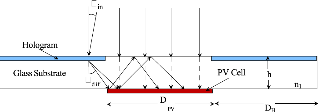
Figure 39. Optochemically organised (a) cubic, (b) woodpile, (c) black and bright lattices. (a) Reprinted with permission from [350] © The Optical Society. (b) Reproduced from [351] with permission from The Royal Society of Chemistry. (c) Reprinted with permission from [352], Copyright (2013) American Chemical Society.
Download figure:
Standard image High-resolution image
Functional optical materials
Self-induced waveguide lattices can be configured with different functionalities. Examples include micropillar arrays that emit light [353] or serve as optical interconnection pins [354]. The mechanical compressibility of micro-trusses [349] and their ability to withstand external stress render them suitable as biological scaffolds, heat exchangers and ultralight metallic micro-lattices. A separate class of functional structures are artificial constructs of arthropodal compound eyes, which are composed of ommatidia—biological waveguides.
These were created by generating hemispherical arrays of self-induced waveguides, which collectively impart wide FOVs [355]. Waveguide encoded lattices (WELs), which also draw inspiration from the collective behaviour of light-harvesting ommatidia, are flexible, slim photopolymer films embedded with self-induced waveguide lattices of varying symmetries [356]. The waveguides confer properties such as panoramic FOV, infinite DOF and enables imaging operations such as focusing and inversion that would normally require bulky optical elements. Importantly, WELs function at all visible wavelengths—from the broad spectrum emitted by incandescent sources (including sunlight) to the discrete wavelength ranges emitted by lasers and LEDs and have been employed as coatings that improve solar cell efficiency [357].
Outlook
Nonlinear waves in photochemical—specifically, photopolymerizable—systems offer unique, photolithographic routes to a rich diversity of 3D waveguide architectures with a range of functionalities. The next generation of lattices could be configured with active functionalities including the ability to compute with incident light; for example, recent findings exploited the spontaneous long-range 2D and 3D self-organization of MI filaments to build a photopolymer cuboid that performed binary arithmetic [358].
Acknowledgments
Funding from the Natural Sciences and Engineering Research Council of Canada, Canadian Foundation for Innovation and McMaster University is gratefully acknowledged.