

Abstract
An enhanced smoothing by spectral dispersion (SSD) scheme via the insertion of a complex coaxial vortex plate in the beamline is proposed. The complex coaxial vortex plate is comprised of an inner vortex plate that induces an azimuthal charge on the beam, and a surrounding vortex plate that induces an opposite charge on the beam. The surrounding vortex plate is supported by a base of same material that generates a time delay between the inner and the outer sub-beams. The time delay then brings about the frequency shift of the sub-beams with frequency modulation and spectral dispersion. As a result of the coherent superposition of the sub-beams, the focal spot exhibits a dominant envelope with transverse motion, and the inside speckles rotate rapidly in the picosecond regime. The simulation shows that the irradiation uniformity is slightly improved via the insertion of the complex coaxial vortex plate. More importantly, the laser-plasma interaction length is significantly shortened and then the reflectivity of stimulated Brillouin scattering is reduced by the use of the enhanced SSD scheme.
Export citation and abstract BibTeX RIS
1. Introduction
In laser-driven inertial confinement fusion (ICF) facilities, laser beam smoothing is quite essential for suppressing the hydrodynamic and laser plasma instabilities [1]. Experiments in the National Ignition Facility (NIF) [2] even reveal that laser beam smoothing is one of the key factors that are related to the success or failure of ignition. Hence, characterization of the laser-irradiation non-uniformity is of critical importance for ICF research since the efficiency with which the non-uniformity in the laser-irradiation imprint target mass perturbations depends on the early time intensity history and also the spatial wavelength of the non-uniformity. The strategy of the smoothing by spectral dispersion [3] with phase plate [4], which is the preferred mechanism for the reduction of the laser-irradiation non-uniformity in glass lasers, is to vary the interference pattern of the phase plate on a timescale that is short compared to the hydrodynamic response of the target (i.e. imprinting time). However, the sweep period of the interference pattern, strongly depending on the modulation frequency of the electro-optic (EO) modulator in smoothing by spectral dispersion (SSD) [5], is much longer than the growth time of parametric backscattering [6] like stimulated Raman scattering (SRS) and stimulated Brillouin scattering (SBS), which disables SSD from suppressing the backscattering. Recent study shows that, the use of spike trains of uneven duration and delay (STUD) pulses can effectively break the accumulation of the parametric backscattering through the transient and intermittent turning on and off the light on picosecond timescale [7, 8]. It is required to develop ultrafast beam smoothing techniques, which not only improve the laser-irradiation uniformity but also have the potential to suppress the parametric backscattering.
The vortex beam—light beam with helical phase and an azimuthal component of the wave vector—can carry orbital angular momentum [9] and is leading to wide-ranging applications in optical microscopy, micromanipulation and free-space communication [10–12]. The technique for generating vortex beam involves free-space light beam through optical elements and plasma-based q-plate [13], etc. Study on the coherent superposition of vortex beams shows that, there are frequency beat between Laguerre–Gaussian (LG) modes that carry different helical charges with frequency shift in their superposition [14]. The frequency beat causes the rotation of the beam profile in the picosecond regime that is related to the frequency shift, which is enormously attractive in laser beam smoothing. In addition, the EO modulator and the grating in the popular SSD have brought spatiotemporal frequency modulation to the light, providing a means to frequency shift the light.
In this paper, we proposed an enhanced SSD scheme via the insertion of a complex coaxial vortex plate (CCVP) in the beamline in high-power laser facilities. The complex coaxial vortex plate comprises of an inner vortex plate that induces an azimuthal charge on the beam, and a surrounding vortex plate that induces an opposite azimuthal charge on the beam. Moreover, the surrounding vortex plate is integrated with a base made of same material that introduces time delay between the inner and the outer sub-beams. The time delay thus causes the frequency shift between the sub-beams and makes their interference structures rotate in the picosecond regime and eventually improve the laser-irradiation uniformity. The rapid rotation of the speckles then contributes to both the improvement of the irradiation uniformity and the suppression of SBS. The paper is organized as follows: In section 2, we present the enhanced SSD scheme and build up the theoretical model. A comprehensive analysis of the smoothing scheme is performed in section 3 before the conclusion in section 4.
2. Physical model of enhanced SSD
The enhanced SSD scheme is illustrated in figure 1. Like the traditional 1D-SSD, the light is frequency modulated by the EO modulator and dispersed by the grating. After amplification in the main amplifier, frequency shift in the triple frequency convertor [15] and spatial phase modulation by a continuous phase plate, the light is finally focused on the target plane. The modification of the enhanced SSD is the insertion of the CCVP (see figure 2). The CCVP is assumed to be a pure phase plate that only induces spatial phase modulation like CPP. Hence, the key enhancement of the novel scheme is the division, reshape of the wavefront, as well as the introduction of frequency shift of the light, which is simple, feasible and potential on the current configuration of high-power facilities like NIF and the Laser Mégajoule [16]. Obviously, the traditional 1D-SSD with phase plate can smooth the focal spot by sweeping the interference pattern of the phase plate on a long timescale (nearly tens of picoseconds), while the enhanced SSD with phase plate can make the interference pattern of phase plate sweep and rotate simultaneously. In this process, the sweep period is tens of picoseconds while the rotation is in the picosecond regime. The inserted CCVP can redistribute the speckles within the focal spot rapidly, as will be discussed below.

Figure 1. Schematic illustration of the enhanced SSD scheme.
Download figure:
Standard image High-resolution image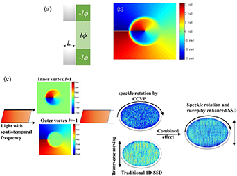
Figure 2. (a) Section view and (b) contour profile of the complex coaxial vortex plate. (c) Illustration of speckle rotation and sweep in enhanced SSD.
Download figure:
Standard image High-resolution imageIn figure 2(c), we can see that the speckle rotation is induce by the frequency shift and the helical charge difference between the inner and the outer vortex, while the speckle sweep is induced by the traditional 1D-SSD. Therefore the illumination uniformity of the enhanced SSD is slightly better than that of the traditional 1D-SSD and has potential in suppressing parametric backscattering. The light after the EO modulator and the dispersion grating and before the complex coaxial vortex plate is expressed by [5]
where A0(t) = exp[-(x/w)2 N-(y/w)2 N] is the normalized amplitude of light field, N is the super Gaussian order, w is the beam width. ω0 is the fundamental frequency, δ and ωm are modulation depth and modulation angular frequency of the EO modulator, respectively. c is the velocity of light, ξ= 2πωm/ω0⋅dθ/dλ represent the dispersion of the grating (the dispersion direction is assumed to be along x axis), and dθ/dλ is the angular dispersion of the grating.
After frequency convertor and CPP, the light field is expressed by
where ΦCPP is the appended spatial phase by CPP.
From equation (2), we can obtain the time-dependent frequency of the light field, i.e.

It can be seen from equation (3) that the frequency of the light varies with the propagation length and the time simultaneously. This spatiotemporal distributed frequency provides frequency beat between the inner and the outer sub-beams based on the complex structure of the vortex plate. According to the structure of the CCVP in figure 2, the spatial phase modulation by the CCVP is expressed by
where r is the radius of the inner vortex plate, l is the helical charge, ϕ= arctan(y/x) is the argument. n and L are the refractive index and thickness of the material like glass.
After the CCVP, the light is divided into two sub-beams carry opposite helical charges and frequency shift. The coherent superposition of the sub-beams on the target plane can be modeled by applying the phase lag associated with the CCVP to the incident beam. The associate phase lag of the sub-beams are
Then, the corresponding focused light can be described as

where Δω= ω(t+ L/c) – ω[t +(n – 1)L/c] is the frequency shift, ϕf is the argument in far field.
Consequently, the focused light on the target plane can be calculated by using the Collins formula, i.e.
where f is the focal length. k and λ are the triple frequency-converted wave vector and wavelength, respectively. (x,y) and (xf,yf) are the near- and far- field coordinates. By use of equations (5) and (7), we can simulate the intensity distribution of the focal spot and further analyze the smoothing performance of the enhanced SSD.
3. Performance of enhanced SSD
Based on the established model above, the smoothing performance of the enhanced SSD is analyzed and compared with the traditional 1D-SSD. The contrast [17], the fractional power above intensity (FOPAI) [18] and the power spectral density (PSD) are used to evaluate the illumination characteristics of the focal spot. The parameters for calculation are listed as follows: The fundamental wavelength and the triple frequency converted wavelengths are 1053 nm and 351 nm, the beam width is w= 186 mm, and the super-Gaussian order is N= 12. The modulation depth and angular frequency of the EO modulator are δ= 2.33 and ωm = 17 GHz for a total bandwidth of ∼0.3 nm. The focal length is f = 7.7 m. For simplicity without loss of generality, the inner vortex plate is 275 mm in diameter to make the energy ratio of the inner and the outer sub-beams 1:1, and its helical charge is l = 1 for example.
3.1. Smoothing performance of enhanced SSD
Firstly, we analyzed the frequency shift between the inner and the outer sub-beams. According to equation (3), the instantaneous frequency of the light varies with the propagation length and the time, that is, there is a frequency shift between the inner and the outer sub-beams. Figure 3 shows how the frequency shift of the center point varies with the propagation length and the time when the thickness of the glass base is 20 mm.

Figure 3. Frequency shift versus the propagation length and the time.
Download figure:
Standard image High-resolution imageIn figure 3, the frequency shift is not constant but varies with space and time, approaching 1.5 THz at maximum. This agrees well with equation (3) that the frequency shift caused by the sinusoidal frequency modulation changes periodically with time. The spatiotemporal frequency shift in figure 3 is caused by the sinusoidal frequency modulation and the grating dispersion, i.e. the color cycle. However, without the two-state shift induced by the base, theses frequency components cannot arrive and interfere on the focal plane simultaneously. Moreover, the thickness choice or the optical length of the base plays a significant role in the maximum frequency shift between the inner and the outer vortex. Owing to the time delay introduced by the base, the frequency shift of the inner and the outer sub-beams is generated. Based on the above result, we can predict that the irradiation uniformity of the enhanced SSD can be improved owing to the multi-direction smoothing of the focal spot including the transverse sweep caused by the grating and the rotation by the CCVP. One more concern is that the base can be made of the same materials with the vortex plate which provides high refractive index, damage threshold and transmittance. As shown in figure 3, the frequency shift distributions induced by 1D-SSD at different moments are different. If there is no substrate on the CCVP, the frequency components modulated by the outer vortex plate and those modulated by the inner vortex plate reach the focal plane simultaneously but without out large frequency shift, then the speckle rotation would not happen. However, if there is a substrate that introduces time delay between the inner and the outer vortex plate, then light field modulated by the inner vortex plate and that by the outer vortex plate at different moments can reach the focal plane at the same time, resulting in the speckle rotation. Moreover, the time delay can be tuned by changing the thickness of the substrate. By comparing the frequency shift versus the propagation length, we find that the thickness of the glass base at 20 mm is appropriate to generate the maximum frequency shift. Hereafter, the thickness of the glass base is assumed 20 mm for example.
We then simulate the focal spots of enhanced SSD and the traditional 1D-SSD at an integration time of 10 ps and 20 ps (see figure 4). It is clear that their intensity envelopes are the same. The focal spots of the traditional 1D-SSD gradually exhibit clear stripping pattern with the increasing integration time, whereas the focal spots of the enhanced SSD show less stripping pattern. Although the stripping pattern gradually emerges with long integration time, it is clear that the rotation of the speckles can mitigate the stripping pattern. The variation of the focal-spot contrasts with the integration time are given in figure 5(a), the FOPAI curves and the PSD curves of the focal spots at an integration time of 10 ps are shown in figures 5(b) and (c).
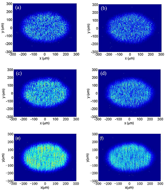
Figure 4. Focal spots of (a) traditional 1D-SSD (contrast = 0.57) and (b) enhanced SSD (contrast = 0.55) at an integration time of 10 ps. (c) Traditional 1D-SSD (contrast = 0.47) and (b) enhanced SSD (contrast = 0.45) at an integration time of 20 ps. (e) Traditional 1D-SSD (contrast = 0.34) and (f) enhanced SSD (contrast = 0.32) at an integration time of 100 ps.
Download figure:
Standard image High-resolution image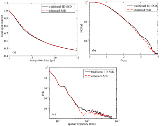
Figure 5. Comparison of smoothing performance of the enhanced SSD and the traditional 1D-SSD. (a) Focal-spot contrast with the integration time, (b) FOPAI and (c) PSD curves of the focal spot at an integration time of 10 ps.
Download figure:
Standard image High-resolution imageIn figure 5(a), the variations of the focal-spot contrasts with the integration time are close. However, the FOPAI curve in figure 5(b) shows that the hot-spot ratio is reduced by the enhanced SSD, and the PSD curve in figure 5(c) indicates that the high-frequency components of the focal spot are alleviated. This is because the speckles in the enhanced SSD rotate and sweep simultaneously rather than those only sweep in the traditional 1D-SSD.
3.2. Influence of CCVP parameters
The CCVP is the core element with the important parameters including the inner radius r and the helical charge l of the inner vortex plate (the helical charge of the outer vortex plate is –l). Hereafter, we analyzed how these parameters impact the smoothing performance in the enhanced SSD, as shown in figure 6.

Figure 6. Smoothing performance of the enhanced SSD affected by the radius of the inner vortex plate and the helical charge, (a) variation of the focal-spot contrast versus the integration time, (b) FOPAI curves at an integration time of 10 ps.
Download figure:
Standard image High-resolution imageIn figure 6, when the radius of the inner vortex plate is the same, the focal-spot contrast curves with different helical charges almost overlap, indicating that the helical charge does not influence the smoothing performance. However, when the radius of the inner vortex plate ranges from 100 mm to 190 mm, which means the energy ratio of the inner beam to the outer beam changes from 0.7 to 1.4, the contrast of the focal spot fluctuates in a small range. Moreover, the FOPAI curves of the focal spots at an integration time of 10 ps illustrate the same results. So, the fabrication requirement of the coaxial vortex plate is not critical, which allows a large tolerance on the inner radius.
The major difference between the enhanced and the traditional SSD schemes is insertion of the CCVP, and thus the redistribution period and direction of the speckles is changed. Though the laser-irradiation uniformity changes a little, the spatiotemporal evolution of the speckles for suppressing parametric backscattering is enhanced, which will be discussed as follows.
3.3. Redistribution characteristics of speckles
In this sub-section, we explored the redistribution characteristics of the speckles in the focal spot. The spatiotemporal evolutions of the laser intensity of the enhanced and the traditional SSD schemes are shown in figure 7. The intensity distributions have been normalized to their maximum and are plotted as a function of the time in the entry plane of the hohlraum (see the online supplementary material (stacks.iop.org/JOPT/22/085607/mmedia)).
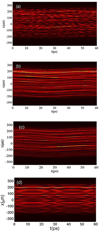
Figure 7. Spatiotemporal evolution of the laser intensities of (a) enhanced SSD and (b) traditional 1D-SSD in the entry plane. (c) Spatiotemporal evolution of the laser intensity of enhanced SSD when the thickness of the substrate is 0 mm. (d) Intensity evolution of the focal spot smoothed by enhanced SSD (angular dispersion of the grating is ignored).
Download figure:
Standard image High-resolution imageAt first glance, it can been seen that the enhanced and the traditional SSD have really different effects on the laser beam propagation without even considering the laser plasma interactions. By drawing the laser intensity evolution over time in the entry plane in figure 7(b), we can clearly see the transversal movement or redistribution of the speckles with the use of the traditional 1D-SSD and the periodical pattern is clearly seen. However, the speckle motion of the enhanced SSD is rather complicated owing to the combined sweep and rotation in two dimensions, as shown in figure 7(a). When there is no substrate, the transversal movement of the speckles are similar with that of SSD, indicating that the accumulation paths of the hot spots are not interrupted effectively, as shown in figure 7(c). Figure 7(d) shows the intensity evolution of the focal spot smoothed by the enhanced SSD without grating dispersion. That is, only the frequency shift and the helical charge difference between the inner and the outer vortex plates affect the speckle motion. At first glance, we can see periodic motion of the speckles. Then, we can find that the speckle redistribution is along the azimuthal direction in a small region. In fact, the aforementioned CCVP makes the speckles rotate in the ps regime by introducing frequency shift of 1.5 THz at maximum and opposite helical charges between the inner and the outer sub-beams. The light paths in the traditional 1D-SSD are continuous whereas that of the enhanced SSD are broken. We have mentioned above that the STUD pulses can reduce parametric backscattering by breaking its accumulation through the transient and intermittent turning on and off the light on picosecond timescale. Fortunately, the enhanced SSD performs analogously by breaking the accumulation path of the hot spots and thus has potential in mitigating the parametric backscattering, as will be discussed in the next sub-section.
In additionally, when focusing on the speckle motion in the x-y plane, we will see complicated motion states of the speckles. First is the transverse motion caused by the traditional 1D-SSD, second is the rotation induced by the CCVP. Therefore, the actual motion of the speckles is the combination of sweep and rotation. Moreover, when the integration time is increased to 20 ps, the difference between the focal spots of the enhanced SSD and the traditional 1D-SSD is the disappearance of the striping pattern, which indirectly demonstrated the existence of speckles rotation. Moreover, the speckle rotation can be analyzed by the use of equation (6). Equation (6) indicates that the intensity modulation on the focal plane is distributed angularly without consideration of CPP so that the speckles are rotated. The rotation frequency of the speckles equals to Δω. Moreover, the angular velocities of the speckles are the same, while the linear velocities vary with the speckle locations.
In equation (6), the intensity distribution satisfies 2 + 2cos(Δωt – 2lϕf), revealing that rotation period of the speckle is T= 2π/Δω, the angular rate equals to the frequency shift Δω, and the radial dependent velocity of the speckle is vspeckle = 2πr/T (r is the radius of the focal spot indicating the location of the speckle). Therefore, the rotation period is inversely proportional with the frequency shift, while the angular rate and the radial dependent velocity of the speckle are linearly proportional with the frequency shift. Particularly, the radial dependent velocity of the speckles decrease with the decreasing radius of the rotation and even decreases to zero in the center point, which may decrease the smoothing performance of the enhanced SSD. However, there are another two key aspects affecting the speckle rotation characteristics. The first is that the frequency shift is distributed non-uniformly (see figure 3), which makes the angular rate and the radial dependent velocity do not exactly meet the aforementioned relationships. Secondly is the spatial phase modulation by the continuous phase plate. When the focal spot is shaped by CPP, the speckle motion characteristics would be more complicated.
Currently, the beam smoothing techniques fall into three categories: spatial smoothing that controls the profile of the focal spot but leads to intensity modulation with high spatial frequency, temporal smoothing that eliminates high-spatial-frequency speckles of the focal spot within a finite time, and polarization smoothing that can improve the uniformity by a factor of  instantaneously. Since laser imprint is particularly sensitive to the initial uniformity of laser beams, only polarization smoothing shows significant improvement [19]. Although the enhanced SSD scheme does not appear likely to smooth the medium-spatial-frequency speckles needed to reduce laser imprint on target, it shows improvement on the reduction of high-spatial-frequency speckles and spatiotemporal evolution of the intensities on the focal plane than the traditional SSD. Moreover, the combination of the enhanced SSD and polarization smoothing is predicted to produce a significant improvement of the uniformity on target.
3.4. Suppression of SBS by enhanced SSD
As a parametric process that can be handled in its simpler form as a convective amplification process, SBS is triggered if the intensity of the speckles is higher than the threshold [20]. Consequently, the CPP-generated hot spots constitute the regions where the parametric processes can grow. Here a simple model reported in [20] was adopted to explain the difference between the enhanced and the traditional 1D-SSD schemes in the saturation level and their oscillations. In this simple model, the propagation characteristics of the smoothed laser beam in vacuum is analyzed by simulating the linear gain for SBS with the consideration of the contra-propagative rays along the direction of propagation. Each ray is assumed independent from the neighbor ones, in which the SBS process is considered as a local process and both diffraction and refraction are neglected. The histograms of SBS gains for the intensity without pump depletion integrated over 10 ps are plotted in figure 8. The number of rays is plotted as a function of the gain in the transverse plane to the calculated average gain value ![]() G
G![]() = 39.86 computed from [20]
= 39.86 computed from [20]
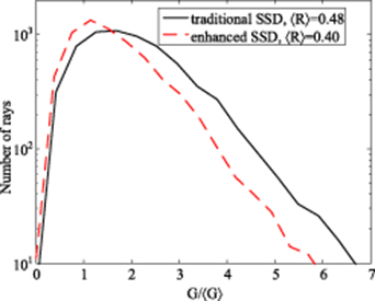
Figure 8. Cumulative histograms for SBS gains over 10 ps for the enhanced and traditional SSD schemes. The standard error in the mean of the histograms for the traditional 1D-SSD and the enhanced SSD are 389 and 410, respectively. ![]() R
R![]() is the average backscattering ratio.
is the average backscattering ratio.
Download figure:
Standard image High-resolution imagewhere l is the plasma length, k2 is the wave number of the IAW, ne and nc are the initial and the critical plasma densities respectively, λD is the Debye length and Cseff/Cs is defined by
where Ti is the ion temperature, Te is the electron temperature, and Z is effective ionization.
The average gain value of nearly 40 is computed without pump depletion, and therefore we can use the Tang equation to analyze the backscattering ratio. The Tang equation [21] to compute the average reflectivity without the consideration of the pump depletion is written as
where noise is the ratio between the noise level of the backscattered electromagnetic wave and the incident wave, R(x,y) and G(x,y) are the reflectivity and the linear gain of the ray (x,y) without pump depletion. The average reflectivity ![]() R
R![]() (x,y) is then computed by ponderating the reflectivity of each ray by the average intensity I(x,y) along the ray, i.e.
(x,y) is then computed by ponderating the reflectivity of each ray by the average intensity I(x,y) along the ray, i.e.
Figure 8 shows the cumulative histograms for SBS gains over 10 ps for the enhanced and the traditional 1D-SSD schemes. If the focal spot is smoothed without any form of SSD but only with CPP, these rays are not swept and their linear gains for SBS continue to increase. Firstly, the linear gains can reach a very high value. Secondly, the linear gain of each ray is close due to spatial smoothing by CPP. Hence the histogram is distributed over a small region with high gain. When SSD is implemented, the cumulative histograms are distributed very widely in both cases, revealing that there is a strong dispersion in the values of the linear gains among different rays. The strong dispersion is caused by the disparity of the maximum intensities of the speckles. Despite the simplicity of the model, we could find that the SBS reflectivity of the enhanced SSD is lower than that induced by the traditional 1D-SSD, indicating that the enhanced SSD performs better in suppressing SBS. Moreover, the standard errors in the means of the histograms for the traditional 1D-SSD and the enhanced SSD are close, indicating that the dispersions in the values of the gains are similar. In figure 8, We can clearly see the maximum gain is 6.6![]() G
G![]() in the traditional 1D-SSD, while it is only 5.9
in the traditional 1D-SSD, while it is only 5.9![]() G
G![]() in the enhanced SSD. Since the gain in figure 8 is mainly driven by the hot spots, we can conclude that the hot-spot ratio is reduced by the insertion of the CCVP. In addition, there exist a few rays with high gain corresponding to the high intensity spots.
in the enhanced SSD. Since the gain in figure 8 is mainly driven by the hot spots, we can conclude that the hot-spot ratio is reduced by the insertion of the CCVP. In addition, there exist a few rays with high gain corresponding to the high intensity spots.
In practical high-power laser facilities, wavefront distortion of laser beams will occur inevitably. When analyzing the influence of the wavefront distortion of the laser beam on the reduction of LPI, it is worth noting that the wavefront distortion in most cases is computed by using the Gaussian random phases. Moreover, the statistical characteristics of the intensity distribution of the focal spot are mainly contributed by the CPP[15]. Hereafter we give the influence of the wavefront distortion on the irradiation uniformity of the focal spot and the reduction of the LPI. The peak-to-valley value of the wavefront distortion is λ (λ is 351 nm), as shown in the following figures 9(a)–(d).

Figure 9. Performance of the enhanced SSD scheme with wavefront distortion.
Download figure:
Standard image High-resolution image
From figures 9(a)–(d), we can conclude that the wavefront distortion would have limited influences on the irradiation uniformity and the reduction of the LPI. In figure 9(d), the mean of the histogram for the enhanced SSD is lower than that of the traditional 1D-SSD, whereas the standard errors in the means of histograms for both schemes are close, indicating that the dispersion in the values of the gains are similar. This is mainly contributed by the spatial smoothing by the CPP. Moreover, The enhanced SSD scheme adopts a complex coaxial vortex plate that is comprised of two vortex plates with opposite helical charges. Each vortex plate can be produced by the use of these methods and the ring base is easy to make [22–24]. Hence it might be potential in practical high-power laser facilities.
4. Conclusion
In conclusion, we presented an enhanced smoothing by spectral dispersion scheme for improving the laser irradiation uniformity and suppressing the parametric backscattering in inertial confinement fusion research. This novel scheme can obtain the same analogous uniform focal spot as the traditional 1D-SSD by simply inserting a complex coaxial vortex plate, which comprises of an inner vortex plate and an outer vortex plate with opposite helical charges and the surrounding outer vortex plate is integrated with a glass base that induces time delay between the sub beams. Therefore, the key point of the enhanced SSD is the division and reshape of the wavefront by the insertion of the complex coaxial vortex plate. Based on the spatiotemporal frequency caused by the EO modulator and the grating, the sub beams are coherent superposed in the focal plane and thus cause the rapid rotation of the speckles. Combined with the transverse sweep by the grating, the focal spot is smoothed in multi-dimensions in the ps regime. The results show that the irradiation uniformity of the laser is slightly improved. The laser-plasma interaction length is significantly shortened and thus the reflectivity of SBS is reduced.
Acknowledgments
We gratefully acknowledge financial support from the National Natural Science Foundation of China (Grant No. 61905167); Research Program of National Major Project of China (Nos. JG2017149, JG2019292, JG2019299); China Postdoctoral Science Foundation (No. 2018M643463); Post-Doctoral Research and Development Foundation of Sichuan University (No. 19XJ0001).
 focal spot smoothed by enhanced SSD (grating dispersion is considered).gif)
 focal spot smoothed by enhanced SSD (grating dispersion is ignored).gif)
 focal spot smoothed by traditional 1D-SSD (grating dispersion is considered).gif)