
Abstract
Whilst many techniques exist for generation of an optical vortex, there remains a need for new devices and methods that can also provide vortex generation with higher powers, greater flexibility of wavelength, and generation beyond the lowest-order Laguerre–Gaussian  mode to address a broader range of practical applications. This work reveals how an all-mirror based interferometric mode transformation system can provide these properties including revealing, for the first time, the generation of a much richer set of vortex mode patterns than might have been thought possible previously. A new developed theoretical formulation, confirmed with excellent agreement by experimental demonstrations in an imbalanced Sagnac interferometer, shows interferometric transformation is possible for all orders of Laguerre–Gaussian
  modes into a rich set of high quality higher-order vortex and vortex superposition. The interferometric approach is shown to be configurable to increase or decrease vorticity. The new mathematical formulation provides the ability to perform a full modal power analysis of both the mode-transformed transmitted vortex and the complementary reflected beam at the Sagnac beamsplitter (BS) port. A discussion is made on the origin of the orbital angular momentum transferred to the vortex output from the Sagnac BS.
Export citation and abstract BibTeX RIS

Original content from this work may be used under the terms of the Creative Commons Attribution 3.0 licence. Any further distribution of this work must maintain attribution to the author(s) and the title of the work, journal citation and DOI.
1. Introduction
Optical beams with a zero intensity phase singularity surrounded by a spiral variation of phase has attracted considerable interest especially since the recognition by Allen et al in 1992 [1] that such structured light beams carry orbital angular momentum. Due to this latter property, these light structures have been called vortex beams and have been used in a number of applications including optical manipulation [2, 3], optical communications [4], and laser manufacturing [5, 6]. There are many methods to generate an optical vortex including spiral phase plate [7], q-plate [8], spatial light modulator (SLM) [9], digital micro-mirror device (DMD) [10], and cylindrical lens pair [11]. There are some limitations in each of these techniques. One issue is the poor power-handling capability of some of these devices e.g. due to absorption and heating that degrades performance, or will even result in permanent damage, in SLMs, DMDs and q-plates. Another issue is the bespoke manufactured fixed plate devices such as spiral phase plates or q-plates will only operate well at their specific design wavelength. A further issue is the high cost of some of these devices, e.g. a high efficiency SLM (~$20 000), or a fixed plate device, particularly if needing bespoke manufacture at a non-standard wavelength. High costs will prohibit or limit commercial implementation of vortex technology in price-sensitive applications.
It was recently shown that a Sagnac interferometer can also be used as an effective technique for transforming a Gaussian mode into a single-charge vortex [12, 13]. Based on a beamsplitter (BS) and simple set of mirrors, a Sagnac interferometer provides a valuable alternative technique for vortex generation. It uses only high-power handling optics as used standardly in high-power lasers, hence, with due care with the input mode size, it should be possible to operate with input power from multi-Watt to multi-kilowatt, and in continuous wave mode and Q-switched and mode-locked pulsed mode using mirror coatings with low loss and low absorption that are commercially available. The Sagnac interferometer, unlike fixed plate devices, can operate over a broadband of wavelengths and over the electromagnetic spectrum limited only by mirror coating technology. Using standard mirror technology, as used by the laser source itself, the Sagnac interferometer provides an off-the-shelf availability and low cost implementation.
In the work of this paper, a new general theoretical formulation is made of interferometry-based spatial mode transformations. The implementation of this focuses on using an imbalanced Sagnac interferometer but is not limited to it, as the same transformations can be achieved in other interferometer configurations. However, as a common-path interferometer, the Sagnac allows vortex generation with an inherent robustness against environmental and mechanical perturbations and, most specifically, automatically achieving the required destructive interference condition at its transmission port. Our new formulation shows that not only can a Sagnac interferometer convert a Gaussian beam into a Laguerre–Gaussian  vortex mode with controlled handedness of vorticity but we show, for the first time to the best of our knowledge, that any input Laguerre–Gaussian
  vortex mode with radial index p = 0 can be transformed. We show that they can be increased in vorticity and transformed into a set of higher-order vortex mode superposition or decreased in vorticity with conversion into a
  mode with vorticity index l decreased by a single unit and radial index increased to p = 1. A full modal analysis is presented of the transmitted and reflected mode powers and a discussion made on the origin of imparted orbital angular momentum from the interferometer.
An experimental demonstration is made of interferometric transformation of higher order vortex modes, for the first time. This is performed with a power transformation fraction of 30%; however, we note that if the interferometer were instead incorporated as a laser output coupler where the unconverted light is recycled back into the laser cavity [14] the conversion fraction automatically approaches 100%. The experimental results show excellent agreement with the theoretical analysis and predictions and demonstrate the high quality and robust nature of the vortex generation. The vortex superposition can be generated with multiple-singularities that also rapidly rotate as they pass through a focus (due to different Gouy phase shifts of the superposed modes). These could provide new potential well structures (with dynamical rotation through the focus) for single and multiple particle optical trapping, rotation and levitation [15], as well as resources for metrology, laser processing at high powers, and potential to provide non-separable or entangled states for quantum technologies at low photon number.
2. Theory of mode transformation with a Sagnac interferometer
We consider a Sagnac interferometer system as shown in figure 1 with a thin-film non-polarising BS and three mirrors (M1–M2–M3) arranged in a planar ring configuration (with plane normal in the y-direction). An incident optical field  with angular frequency ω, wavenumber
  wavelength
  complex field amplitude E, and polarisation state
  (which we take as linear polarised throughout this analysis) is split into clockwise
  and anticlockwise
  field amplitudes at the BS. When perfectly aligned to follow the same ring path these fields coherently recombine at the BS to give a transmitted field
  and a reflected field
  where
where  and r are the field transmission and reflectivity of the incident light field at the BS (from air to glass),
  and
and  are the values from the reverse direction at the BS (from glass to air), and LR is the optical path length of the ring. The sign convention used
  results from the π phase shift at the glass to air interface but the destructive interference condition for the transmitted ring components is valid for any non-absorbing BS. The two ring field components interfere destructively at the transmission port and constructively at the reflection port. This interference condition is independent of wavelength
  and the ring path length
  since these are identical for the two ring directions due the common-path nature of the Sagnac interferometer. This is a useful property of the Sagnac interferometer providing insensitively to mechanical or environmental path length perturbations and allows operation even with spectrally broadband fields or ultrashort pulses with low temporal coherence.
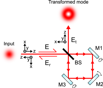
Figure 1. Schematic of an optical field E incident on a Sagnac interferometer formed by a beamsplitter (BS) and a set of mirrors (M1–M2–M3) creating a resultant transmitted output field Et and a reflected field Er.
Download figure:
Standard image High-resolution imageFor a 50% BS ( ), the transmitted field
  is zero and all the return light goes into reflected field
  However, if there is an asymmetry between the relative clockwise and anticlockwise beam paths the two fields returning to the BS are unbalanced and a non-zero resultant transmitted field
 ![${E}_{t}=1/2[{T}_{+}\left(E\right)-{T}_{-}\left(E\right)]{e}^{ik{L}_{R}}$](https://content.cld.iop.org/journals/2040-8986/22/1/015604/revision2/joptab5c8dieqn23.gif) can be created where
can be created where  are the asymmetric spatial transformations of the field in the two ring directions. The corresponding reflected field
 ![${E}_{r}\,=1/2[{T}_{+}\left(E\right)+{T}_{-}\left(E\right)]{e}^{ik{L}_{R}}.$](https://content.cld.iop.org/journals/2040-8986/22/1/015604/revision2/joptab5c8dieqn25.gif)
It has been shown that by destructively interfering two Gaussian beams with relative shear displacement in one axis (y) and with a relative angular offset in the orthogonal axis (x) it is possible to generate a vortex beam [13]. The destructive interference is automatically and robustly achieved in the transmission port of the Sagnac interferometer of figure 1. The shear transformation can be perform by vertically tilting mirrors M1 and M3 in opposite directions by an equal amount to create relative upwards and downwards out-of-plane small displacements  and the angular transformation by rotating mirror M2 in the horizontal axis to create the in-plane small angular offsets
  between the two opposite ring directions [16]. This procedure for the Sagnac interferometer creates the asymmetric transformations
  for the fields in the two opposite ring directions.
For the analysis, we take the displacement and angle combination  in the (clockwise) beam experiencing two BS transmissions
  and the opposite combination
  in the (anticlockwise) beam experiencing two BS reflections
  that interfere to give the transmitted output
  Other cases will be discussed later. We consider a general input field with complex amplitude
  and the Sagnac transmitted and reflected fields for the case of a 50% BS with small angular offset (
 ) are given by


For simplicity of notation the common ring phase factor  has been dropped but can easily be re-incorporated. An important insight into the shear displacement is to expand the displaced fields as a Taylor series
  for displacement
  much smaller than the characteristic scale on which the field varies significantly, which for a Gaussian field is the waist size w. Equation (1) then can be written as:
Using series expansion of the sin and cos terms and taking terms up to second-order:  we obtain a simplified set of Sagnac transform equations:
Equations (3a) and (3b) form a set of master equations and due to their relative mathematical simplicity are found to be very instructive as a basis for understanding the spatial transformation potential of the Sagnac interferometer for any input spatial mode or general coherent modal combination 
3. Interferometric transformation of Laguerre–Gaussian modes
Laser spatial eigenmodes typically fall into either the set of Cartesian Hermite-Gaussian (HGmn) modes or the set of cylindrical coordinate Laguerre–Gaussian (LGpl) modes. We consider here the LGpl modes whose field distributions in normalised form are given by [17]
where  is the Gaussian radial waist size and
  is the wavefront radius of curvature,
 are generalised Laguerre polynomials with argument
  and radial index p and azimuthal index l, with cylindrical coordinates
  having radial distance
  and azimuthal angle
  Phase terms
  are the mode-dependent propagation Gouy phase factors where zR is the Rayleigh distance. For the LG modes the term
  is an azimuthal spiral phase providing the defining feature of a vortex field possessing orbital angular momentum with topological charge l. The coefficients
  are normalisation factors such that
  The LG modes possess the mathematical property of orthogonality
  for different modes.
Setting the Sagnac interferometer at z = 0, input modes are taken to have a plane phase front, Gouy phases  and
and  corresponding to the minimum Gaussian waist size. Since mode transforming displacement and angular imbalances of the Sagnac interferometer are in Cartesian
  directions, it is convenient in the following mathematical formulation to express LG vortex modes in Cartesian notation. For the case p = 0, equation (4a) becomes
where  is a normalisation constant at
  and we have used the relation
  where the upper and lower sign correspond to positive and negative sign of l, respectively.
3.1. Transformation of Gaussian mode to a first-order vortex mode
Consider first the simplest case of a fundamental Gaussian mode as the input field to the Sagnac interferometer  where w = w0 and
  is the normalisation constant. In this case, equation (3) leads to transmitted and reflected output fields:
Equation (5) has been written in a form so it is easy see that there is a canonical condition  under which the pre-factors in the y and x terms of the transmitted field have equal magnitude. Under this condition, the transmitted and reflected fields take on the form:
In equation (6a), the transmitted field is expressed as a normalised Laguerre–Gaussian vortex mode  with topological charge
  by noting
  It has amplitude proportional to
  the ratio of the imbalance displacement of the Sagnac interferometer to the Gaussian beam waist size. The reflected beam at the Sagnac BS, given by equation (6b), is an attenuated fundamental input mode
  and with the addition of a
  Laguerre–Gaussian mode component with topological charge
  by noting
  and
and 
Modal power analysis of equation (6) can be performed by taking the integral  of the transmitted and reflected fields and using the orthogonality property of the modes. The ratio of the transmitted vortex
  power
power  to the input power
  of the fundamental Gaussian
  is
is  The reflected power
  has power-reflectivity
  by considering terms up to second-order in small parameter
  To this order of approximation, the reduction of the reflected Gaussian power is equal to the transmitted power. The second order vortex
  component present in the reflected field has a modal power content
  and is a weak term for small displacement.
This modal analysis shows that there is energy conservation to second-order in small parameter  the power of the transmitted
  vortex mode equals the power lost in the Gaussian
  reflection component. However, there is an imbalance between the orbital angular momentum of the input and output fields that implies an angular momentum transfer to the transmitted optical field by the Sagnac interferometer system. Inside the Sagnac interferometer the two counter-propagating beams are still Gaussian and carry no angular momentum until they interfere at the BS and it implies this BS component is the source of the angular momentum. The two beams are incident from opposite sides of the BS and by momentum change on reflection will induce forces on the BS. The vertical shear beam displacements will create a net torque in the vertical direction whilst in the horizontal axis there will be unbalanced force components as the two beams incident at different angles create an increasing off-axis reflection imbalance.
The vorticity direction to generate the  mode with
  was determined by the choice of combination of sign of displacement
  and angular offset
  in the current analysis. By reversing the direction of either displacement or angular offset gives a coordinate transformation in equation (3) such that the transmitted field has a form
  equivalent to changing the handedness of vorticity to topological charge
  and generation of the
  mode.
mode.
3.2. Higher-order vortex generation
The previous section showed that the shear displacement and angular offset transformation of the unbalanced Sagnac interferometer can be used for conversion of a Gaussian input  into a first order vortex with
  with the sign of vortex simply switchable by reversing the direction of either the shear displacement
  or angular offset
  It is also easily shown from equation (5a) that if only the shear displacement
  is used (
 ) then the incident
  mode is converted to a pure Hermite-Gaussian
  mode and if only the angular displacement
  is used than it is converted to a pure
  mode.
mode.
The Sagnac transformation master equation (3) can also be applied to more general field input cases including high-order mode input, superposition of modes, and other field distributions. To aid the mathematical formulation, it is useful to note that all Laguerre–Gaussian modes (and Hermite-Gaussian modes) and superposition of such modes, have the same general mathematical form

Applying equation (7) to the master set of Sagnac transform equations (3a) and (3b), and applying the canonical condition  the transmitted and the reflected fields, for a generalised modal input field is given by:
Using equations (8), it is now a simple matter to investigate the transformation of a variety of high-order and mode combinations input into the Sagnac interferometer. Figure 2 shows Sagnac mode transformation into the transmitted field for the first three Laguerre–Gaussian  vortex modes l = 0, +1, +2. The details of these field transformations and their modal analysis and of the general set of
  vortex modes are expounded in the follow sections.

Figure 2. The intensity (left side) and phase (right side) when applying the Sagnac transform to an input mode (middle row), where the transform increases (top row) or decreases (bottom row) the vorticity into the transformed mode.
Download figure:
Standard image High-resolution imageWe can first see that for the simplest case of a Gaussian input field to the Sagnac interferometer  where
where  and
and  equation (8) leads to the same transmitted vortex and reflected field solutions as previously derived in equation (6).
It is interesting then to consider what happens for the case of the input field being itself a vortex. For the lowest-order vortex mode input field ![$E\left(x,y\right)={\rm{L}}{{\rm{G}}}_{01}\,={C}_{01}\left[\left(y+ix\right)/w\right]{e}^{-({x}^{2}+{y}^{2})/{w}^{2}},$](https://content.cld.iop.org/journals/2040-8986/22/1/015604/revision2/joptab5c8dieqn109.gif) the transmitted and reflected fields are straightforwardly derived from equation (8)
the transmitted and reflected fields are straightforwardly derived from equation (8)
These can also be expressed in cylindrical coordinates and modal content by noting normalisation constants 
Equation (10a) shows that the Sagnac transforms a first-order vortex input field  into a superposition of a second-order vortex mode (
 ) and a fundamental mode (
 ). The intensity pattern of this superposition has two symmetrically displaced singularities each with a single positive unit of topological charge, as shown in figure 2. The transmitted
  and
and  mode components have power ratios relative to the incident
  mode:
mode:  and
and  respectively. The reflected field given by equation (10b) consists of an attenuated
  mode and a weak
  mode component. To second-order in small parameter
  the reflected power
  has a loss that balances the total transmitted power.
For the more general higher order vortex mode ( ) with positive
  as input field
 ![$E(x,y)\,={C}_{0l}{\left[\left(y+ix\right)/w\right]}^{l}{e}^{-({x}^{2}+{y}^{2})/{w}^{2}},$](https://content.cld.iop.org/journals/2040-8986/22/1/015604/revision2/joptab5c8dieqn125.gif) equation (8) leads to the transmitted field
equation (8) leads to the transmitted field
by noting 
The Sagnac output is seen to transform a general high-order input vortex field of order l into a superposition of two vortices ( and
and  ) with orders
  and
and  one above and one below the incident field. The transmitted power ratios for
  and
and  modal components are
  and
and  The transmitted power for a given shear displacement parameter
  increases with vortex mode order
The reflected field can be found with equation (8b) and ![$f={C}_{0l}{\left[\left(y+ix\right)/w\right]}^{l},$](https://content.cld.iop.org/journals/2040-8986/22/1/015604/revision2/joptab5c8dieqn137.gif)
![$df/dy={C}_{0l}/wl{\left[\left(y+ix\right)/w\right]}^{l-1}$](https://content.cld.iop.org/journals/2040-8986/22/1/015604/revision2/joptab5c8dieqn138.gif) and
and ![${d}^{2}f/d{y}^{2}={C}_{0l}/{w}^{2}l(l-1){\left[\left(y+ix\right)/w\right]}^{l-2}.$](https://content.cld.iop.org/journals/2040-8986/22/1/015604/revision2/joptab5c8dieqn139.gif) It has the form of an attenuated version of the input
It has the form of an attenuated version of the input  mode with field amplitude
 ![$\left[1-(2l+1){\left({d}_{y}/w\right)}^{2}\right]{\rm{L}}{{\rm{G}}}_{0l}$](https://content.cld.iop.org/journals/2040-8986/22/1/015604/revision2/joptab5c8dieqn141.gif) and, to second-order in parameter
and, to second-order in parameter  a power reflectivity
  The reflected field has additional weak higher-order
  and lower-order
  vortex mode components (for
  ).
).
3.3. Mode transformation with interferometer imparting 'negative' vorticity
In the previous cases, the Sagnac added vorticity with the same handedness to the incident vortex mode. The Sagnac can also be configured to remove vorticity. This can be accomplished by switching the relative displacement or angular shift of the Sagnac interferometer to reverse direction of vorticity transfer of the interferometer to the input vortex mode. Changing the sign of the angular shift is equivalent to replacing  with
with  in equations (8a) and (8b) to give:
For the case of lowest order vortex  the transmitted and reflected fields are
The transmitted field can be expressed in cylindrical coordinates and in a modal description
noting  and generalised Laguerre polynomial
  The Sagnac transforms
  into a pure
  mode which has no vorticity (l = 0) and has a single (p = 1) zero amplitude ring at
  The intensity pattern of the
  mode is shown in figure 2. The Sagnac has removed a single unit of topological charge resulting in the loss of net vorticity (zero topological charge). However the field is not reconverted to a Gaussian
  but to a radial mode
  (with
(with  ).
).
The reflected field has the form of an attenuated version of input  mode. Again, the decrease in the power of the reflected field is equal to the generated power of the
  transmitted mode. The reflected field also has weak
  and
and  modes, both having topological charge −1.
For the general vortex order  as input field
 ![$E\left(x,y\right)={C}_{0l}{\left[\left(y+ix\right)/w\right]}^{\left|l\right|}{e}^{-({x}^{2}+{y}^{2})/{w}^{2}},$](https://content.cld.iop.org/journals/2040-8986/22/1/015604/revision2/joptab5c8dieqn164.gif) the resultant transmitted field with 'negative' imparted Sagnac vorticity is given by
the resultant transmitted field with 'negative' imparted Sagnac vorticity is given by
by noting  This shows all vortex mode orders
  transform to a pure
  mode with reduced vorticity
  and increased radial index
  The transmitted power ratio
  unlike the Sagnac case adding vorticity, is independent of vortex mode order
  The reflected beam is an attenuated
  mode with power reflectivity
  and analysis from equation (12b) shows there is a weak mode component
  with radial index
  and vorticity
  by noting generalised Laguerre polynomial
4. Experimental verification of vortex mode transformation
The previous sections provide new analysis of the vortex transformational properties of the unbalanced Sagnac interferometer. This section provides an experimental demonstration to test the validity of the theoretical analysis.
A diagram of the Sagnac interferometer used for the mode conversion is shown in figure 3. The interferometer consisted of three mirrors M1, M2, and M3 and a 50/50 BS, and had a perimeter of 12 cm. To perform the mode conversion, the opposite vertical shear  was adjusted by rotating a 3 mm thick anti-reflection coated glass plate that was inside the Sagnac interferometer. Rotation of the plate about the beam x-axis resulted in opposite vertical shear between the counter-propagating beams and the direction of rotation was reversed to either increase or decrease the output vorticity. Details of this method of control are given in [14]. The opposite horizontal angular tilt
  was controlled by rotating mirror M2 about the beam y-axis. The input mode was imaged with a single lens to a planar beam waist at M2 to match the plane-wave theoretical construction of the previous sections. The input beam to the Sagnac interferometer was from a vortex generating laser of our own design described in a previous publication [18]. This laser produced high quality LG00, LG01 and LG02 modes of pure handedness at 1064 nm.

Figure 3. The experimental configuration of the Sagnac interferometer mode conversion, which used a 3 mm thick glass plate for vertical shear control and M2 rotation for horizontal angular tilt.
Download figure:
Standard image High-resolution imageThroughout the experiment the mode conversion parameters of displacement and angle  were kept small by maintaining a canonical condition of
  This meant the transmission of the device was maintained below 30% and the reflected mode was unchanged from the input as expected. The waist radius of the underlying Gaussian (
 ) on M2 was 30 μm, so to maintain the desired canonical condition this determined a plate rotation angle of 7 mrad to give
  μm, and
  mrad by rotating M2 by half that amount. Both of these rotations were easily controlled and maintained by standard opto-mechanical mounts. Additionally, once configured the vortex output of the interferometer was highly stable over long periods (no observable change over at least 15 min), in part due to the common path design of the Sagnac interferometer making it stable against environmental perturbations.
The experimental mode conversion results are shown in figure 4, with left-side of diagram showing far-field intensity profiles of the input and transmitted modes, and right-side their interferometric phase profiles. The far-field intensity profiles of the converted modes match well with the theoretical predictions in figure 2, but the mode superpositions are rotated 90° compared to the beam waist theoretical calculations, as expected, due to the differing Gouy phase changes  as seen in equation (4a), between the component modes when propagated to the far-field. In addition to replicating the intensity nulls of the theoretical calculations, the experimentally converted modes propagated with close to the expected beam propagation M2 parameter. The output LG01, LG10, and LG11 modes had measured M2 parameters of 2.1, 2.8, and 4.3, which match well to the theoretical values of 2, 3 and 4, respectively.

Figure 4. Results of the experimental LG00, LG01 and LG02 mode conversion showing the far-field intensity profiles (left side), and interference pattern when combined with a tilted plane wave (right side). The Sagnac transform is applied to the input mode (middle row) and either increases (top row) or decreases (bottom row) the vorticity of the input.
Download figure:
Standard image High-resolution imageTo investigate the phase structure of the modes, a Mach–Zehnder was used to interfere the modes with a tilted plane wave reference of itself. In this configuration a phase singularity is revealed as a 'fork' pattern in the interferogram by introducing extra fringes from its additional 2π phase. The number of fringes determines the order of the vortex, the integer multiple of 2π phase change it has, and the position of the extra fringe above or below the singularity determines the direction of the vortex [19].
The experimental phase interferograms in figure 4 verify that when the mode converter is configured to increase the mode vorticity the number of additional fringes on the upper half of the beam increases by one. This corresponds to an additional 2π phase change around the whole mode. When decreasing the mode vorticity with an LG00 input the converted mode has the opposite handedness, for an LG01 input the returned mode has no vorticity, and for the LG02 input the returned mode has decremented the vorticity by one.
To demonstrate the propagation stability of the transformed modes, the evolution of the second moment beam radius of the LG00 + LG02 superposition through a focus is shown in figure 5, along with the beam intensity profile in the near and far-fields. The beam radii are fitted with the Gaussian beam propagation formula, which yields beam propagation parameters in the horizontal and vertical planes of  and
and  respectively. The inset intensity profiles show that the beam is unchanged in the near and far fields, aside from a rotation through the waist. This is due to a changing Gouy phase difference between the LG00 and LG02 components, and the angle of rotation is equal to the Gouy phase shift
  All of the converted beams were similarly propagation invariant, with the mode superpositions rotating through 180°.

Figure 5. The experimentally measured beam radius on propagation through a waist of the LG00 + LG02 superposition in the horizontal (red circles) and vertical (black squares) planes, each fitted to the Gaussian beam formula (solid lines). The inset intensity profiles are centred on their measurement position.
Download figure:
Standard image High-resolution image
5. Conclusions
This work analyses the path imbalanced Sagnac interferometer to provide new insights into its mode transformational ability. Vertical shear displacement combined with an angular wavefront displacement between the two Sagnac field components in opposite ring directions is mathematically formulated into a system of transformation equations. Solution of the transform equations allows detailed mathematical analysis of the resultant transmitted and reflected fields at the Sagnac interferometer BS, for the first time, for arbitrary input Laguerre–Gaussian  vortex mode. There is a canonical relationship between the shear and angular displacement, which is found to be the same for all vortex input modes, which leads to the Sagnac interferometer imparting an increase or decrease in the vorticity of an input field. A fundamental Gaussian
  is transformed to a pure Laguerre–Gaussian
  vortex mode of topological charge l equal to either +1 or −1 whose sign of vorticity is controlled by the relative sign of the shear and angular displacements. Whilst the latter property has been previously described [13], the more general mathematical formulation of this paper has also shown for the first time, to the best of our knowledge, that higher-order charge vortex input field
  can also be transformed into new modal fields. If the interferometer imparts vorticity in the same direction as the input vortex, the transmitted beam is a coherent combination of two vortex modes, one with higher topological charge
  and one with lower topological charge
  If the handedness of the transferred Sagnac vorticity is opposite to the input vortex
  then the transformed output field is another pure Laguerre–Gaussian mode
  reduced in vorticity by one unit of topological charge
  and at the same time increased in radial order
  with a single zero ring structure.
Experimental verification of the predictions of the vortex mode transformation theory has been performed. The results shown in figure 4 match closely to the theoretical predictions shown in figure 2, in both amplitude structure and phase vorticity/singularities. The experimental propagation of a superposition mode shows its propagation stability and the rotation of the phase singularities as the beam passes through the focus, due to the different Gouy phase shifts of the two modes in the superposition.
The significance of this work is the potential new opportunities afforded by the Sagnac interferometer for formation of vortices and coherent superposition of vortices whose multi-singularity structures could have applications for optical trapping and levitation, metrology, laser processing, and as a resource in quantum systems [15]. This is especially so with a simple mirror-based interferometer whose high-power handling capability allows vortex generation at high powers/energies and with wide choice of laser wavelength and ultrashort pulses, without requirement of bespoke manufactured fixed plate optical elements or high cost programmable devices (e.g. SLM and DMD) that currently suffer with vulnerability to high laser flux [20]. The analysis of this work can be extended more generally to other interferometer systems, although the Sagnac has advantage of robust common-path and automatic destructive interference at the transmission port that is required for the vortex generation.
Finally, it is noted that the unbalanced Sagnac interferometer has maximum transmission of 50% and generates high quality vortex mode up to about 30% transmission or so as demonstrated recently [16] and in the results of the experimental section 4 of this paper. However, if the Sagnac interferometer is used as an end mirror to a laser cavity, in which case the un-transmitted (reflected) beam is recycled to the laser cavity, the efficiency of the interferometric mode transformation can be raised to near 100%, if the optics in the interferometer are near lossless. In this context, we have recently demonstrated that the Sagnac acting as a vortex output coupler provides high quality and high efficiency generation of controlled handedness vortex  modes from a laser cavity supporting a Gaussian fundamental internal mode [14]. The extended analysis of our current paper shows that a laser supporting higher order vortex modes could directly output more complex higher order modes and superpositions by using the unbalanced Sagnac interferometer as an output coupler. This laser could be based on previously presented designs, for example using coupled laser cavities [18] or annular pumping geometries [21]. The mode-dependent transmission and reflectivity of the Sagnac device can provide mode filtering and opportunities for intracavity mode selection and vortex handedness control.
Funding
Engineering and Physical Sciences Research Council (EPSRC) (EP/R511547/1); EPSRC Quantum Systems Engineering Skills and Training Hub studentship, Imperial College London (EP/P510257/1).