

Abstract
In this work, we propose a very simple, and efficient interferometric setup for transforming a homogeneous linearly polarized beam into a radially polarized beam. The proposal is based in a double-aperture common-path interferometer adapted for phase-shifting of π radians per quadrant. It is carried out by placing two composed grating in each aperture, which are built by joining two gratings displaced by a half-period, on horizontal and vertical direction, respectively. The input optical beams are orthogonal and linearly polarized, and their amplitudes are modulated in quadrature. We show that the combination of amplitude-only filters and the π phase-shifting per quadrant can achieve the implementation of complex filters such as the sinusoidal ones. The combination of the spatial modulation of both amplitude and phase generates an optical field with radial polarization. Specialized optical elements of high cost and SLM devices are avoided. We show the theoretical model and experimental results.
Export citation and abstract BibTeX RIS
1. Introduction
Polarization is one of the fundamental characteristics of electromagnetic waves. The light is a wave of this kind, and the control of its polarization state plays an important role in many optical applications. In the last few decades, there has been a growing interest in optical fields with spatially variant polarization states. Good examples are the cylindrical vector beams (CVBs) [1], which have been investigated due to their special characteristics such as their strong longitudinal electrical component in the focal plane and its tight focal beam spot [2–4]. These characteristics make them especially useful in applications such as metal cutting [5], electron acceleration [6], optical lithography [7], guided [8] and particles trapping [9], optical communications [10], and in the increase of resolution in microscopy [11], among others things.
There have been many works focused on the creation and manipulation of the classic CVBs radial and azimuthal beams, which are typically described as the superposition of two first-order Hermite-Gaussian modes, TEM10 and TEM01 [12]. There are two main methods in the generation of these beams: extra-cavity and intra-cavity also called passive and active methods respectively. In the intra-cavity approach, the laser resonator itself is modified by elements placed inside the cavity to produce the modes of resonance TEM10 and TEM01. Many publications have reported different techniques for generating polarized beams by using active methods [5, 13–15]. However, special fabrication techniques for non-standard optical elements are often required; also, the beam is fixed once the laser cavity is designed, and this clearly represents a loss of flexibility.
In contrast, the extra-cavity approach allows a conversion of the TEM00 beam into the TEM10 and TEM01 modes outside of the laser cavity. This method gives flexibility and reduce cost in applications. Within this category, there is also a wide variety of techniques that allow converting a homogeneously polarized beam into a CVB. Among them are those that use specialized optical elements, such as continuous or sectored spatially varying retarders [16, 17], subwavelength gratings [18], half waveplates [3, 19], Wollaston prisms [20], plasmonic surfaces [21], diffractive optical elements (DOEs) [22–24], and optical fibers [25] among others things. Spatial light modulators (SLMs) aroused great interest and have been studied extensively because they allow a dynamic and programmable modulation of both amplitude and phase of the optical field, having a good flexibility [20, 26–30]. Different schemes have been proposed by using one or more SLMs [29–31], either the modulating optical field could be only by the SLM [29] or with the support of other specialized optical elements [20, 30]. However, this type of polarization conversion carries a high design cost.
Another type of technique used in the generation of the CVBs are the interferometric ones [3, 19, 27, 30, 32]. Tidwell et al [32] proposed to apodize a TEM10 beam before the input of a Mach–Zehnder interferometer, and then rotate the optical field in one of the arms by using a periscope. In this way, the superposition of two orthogonal beams was obtained. Following this idea, Youngworth and Brown [3] and later Passilly et al [19] created the modes TEM10 and TEM01 by placing a phase step filter of π radians on the middle of each polarized arm in a Mach–Zehnder interferometer. The phase step has been created by using λ/2 waveplates, tilted glasses, polymer films, and also by SLM devices [30, 31], where each quadrant of the optical field passes through different optical paths. But these schemes often are difficult to calibrate, as well as being more susceptible to environmental or other disturbances. The common-path interferometer schemes are very useful in reducing these drawbacks. Khonina et al proposed very simple schemes by using only-phase DOE's coupled in each of the two apertures of a 4f system [22], by use of multiorder DOEs arrangement instead of lenses [23] and lately by a binary DOE on a Sagnac interferometer [24]. Because the diffractive optics are highly efficient in obtaining any desired modes from the principal laser mode, it is able to generate higher-quality inhomogeneously polarized beams. However, these types of specialized devices are designed for a specific separation, focal length, and wavelength. Also, DOEs have a high fabrication complexity.
In this work, we propose a technique to convert a homogeneous linearly polarized beam into a radially polarized beam, taking advantage of the simplicity of the interferometric schemes while reducing the problems associated with calibration and stability. The setup is based on a double-aperture common-path interferometer (DACPI) in whose input plane is placed two modulated Ronchi ruling and two orthogonal polarizers in order to separate the polarization components. The setup is more stable than a standard two-arm interferometer, and the optical path difference is easily calibrated by transversal or rotational displacements of the gratings [33]. Another critical point in the polarization conversion by interferometric techniques is the creation of the spatial phase-shifting. Since the TEM10 and TEM01 modes are typically performed by generating a π phase-step in the middle of one or both interferometer arms, the shifter elements must be correctly aligned so that the phase-shift is adequate. In addition, generally the phase shift is dependent on the wavelength. We propose to encode the phase-steps directly into the two Ronchi rulings of the input plane by displacing the gratings lines by half of the period. Thereby, by means of a correct distribution of the grating lines by quadrants, a relative phase differences of π is introduced. In this way, the phase shift is independent of both the wavelength and the degree of expertise of the user. In addition, the light beams always cross the same optical path. Another additional advantage is the use of only basic elements such as lenses and polarizers, therefore, the cost of the implementation is greatly reduced. Moreover, we demonstrate that the modulated Ronchi rulings can be printed on conventional printers.
2. Theoretical analysis
The mathematical description of a light beam with resonance mode TEM00 and elliptically polarized by using the Jones matrix formalism is:

where E0 is the amplitude of the Gaussian beam, and σ represents the components amplitude rate, which is defined in the range of [0, π/2]. αx and αy are the phases of horizontal and vertical components, respectively, in such a way that the relative phase difference is α = αy − αx. A light beam with a homogeneous polarization is that one in which α and σ are spatially constants; otherwise, the polarization is called no-homogeneous or spatially variant. Examples of spatially variant polarizations are the radial and azimuthal beams. According to [32, 34], the mathematical description of a radially polarized light beam is:

This beam has a cylindrical symmetry, hence the orientation is determined by the azimuth angle ![$\theta \in [0,2\pi ]$](https://content.cld.iop.org/journals/2040-8986/21/5/055602/revision2/joptab1410ieqn1.gif) , whose origin corresponds to the horizontal-axis. The light beam is always linearly polarized at every point.
, whose origin corresponds to the horizontal-axis. The light beam is always linearly polarized at every point.
Thus, to create an experimental radial beam from (1), the amplitude distributions should be modulated as  and
and  for the horizontal and vertical beam components, respectively. At the same time, α = 0 is preferred. Nevertheless, only in the the region where
 ![$\theta \in \left[0,\pi /2\right]$](https://content.cld.iop.org/journals/2040-8986/21/5/055602/revision2/joptab1410ieqn4.gif) the amplitudes of the sine and cosine functions are positive. When
the amplitudes of the sine and cosine functions are positive. When ![$\theta \in \left[\pi /2,3\pi /2\right]$](https://content.cld.iop.org/journals/2040-8986/21/5/055602/revision2/joptab1410ieqn5.gif) , the amplitude of the cosine function is negative as the sine function when
, the amplitude of the cosine function is negative as the sine function when ![$\theta \in \left[\pi ,2\pi \right]$](https://content.cld.iop.org/journals/2040-8986/21/5/055602/revision2/joptab1410ieqn6.gif) . This restricts the generation of radial polarization by the modulation of the only amplitude of two orthogonal TEM00 beams. However, taking into account the identity of Euler,
. This restricts the generation of radial polarization by the modulation of the only amplitude of two orthogonal TEM00 beams. However, taking into account the identity of Euler,  , it is feasible to associate the negative amplitude with a phase charge of π. Therefore, for a radially polarized beam (1) becomes:

with ![${\alpha }_{x}^{* }=\left\{\begin{array}{c}0,\,\theta \in \left[-\pi /2,\pi /2\right]\\ \pi ,\,\theta \in \left[\pi /2,3\pi /2\right]\end{array}\right.$](https://content.cld.iop.org/journals/2040-8986/21/5/055602/revision2/joptab1410ieqn8.gif) and
and ![${\alpha }_{y}^{* }=\left\{\begin{array}{c}0,\,\theta \in \left[0,\pi \right]\\ \pi ,\,\theta \in \left[\pi ,2\pi \right]\\ \end{array}\right.$](https://content.cld.iop.org/journals/2040-8986/21/5/055602/revision2/joptab1410ieqn9.gif) .
.  corresponds to TEM10 mode while
  corresponds to TEM01 mode representation [19, 30].
The easiest way to achieve this spatial relative phase difference is to place waveplates of λ/2 in the desired regions as [3, 19]. Nevertheless, this means that in different regions the light beam will cross a longer optical path than in other regions. To avoid this, the authors propose to modulate each orthogonal optical beam by the theory exposed in [35].
2.1. Phase modulation
As is known [33, 35–38], a DACPI consists of two lenses, L1 and L2, separated by a distance 2f, where f is the focal distance of both lenses; the DACPI containing three planes. In the first place, the input plane contains two apertures, wH and wV, separated vertically by a y0 distance. The wH aperture supports a horizontal polarizer, while wV supports a vertical polarizer in order to separate the polarization components. Additionally, in each aperture a Ronchi ruling Rs, with s = H, V, displaced by qsd, of period qp, and bright bar qw is placed on a qs axis, which is rotated at φs angle with respect to the x-axis as shown in figure 1, and is defined as  .
.

Figure 1. Double-aperture common-path interferometer setup with two orthogonal polarizers in the input plane.
Download figure:
Standard image High-resolution imageIn the Fourier plane, a third Ronchi ruling is used as a spatial filter:  , of period νp, and bright bar νw, with its bars parallel to the horizontal axis displaced by νd. Because of L1, the optical field at this plane is described by the Fourier-transform of the input optical field given by a train of replicas of the input optical field. Thus, it is convenient to isolate the first replica only by using a spatial filter conditioned that frequency components of the input field are small enough so that two neighboring diffraction orders do not overlap. Finally, at the output plane, because of L2, the optical field, E(x, y), is given by the inverse Fourier-transform of the optical field at the Fourier plane, and consist of a replica set of the initial optical field modified and centered in position
  , where n is the diffraction order. Therefore, if the aperture separation at the input plane is
  , and thus the +1st order horizontal field overlaps with the −1st order of vertical aperture field, then the matched condition has been assumed. The vector of the optical field at output plane is given by

where E0c is the complex beam amplitude,  , and
, and  , here
  . The amplitudes coefficients are
  , and
, and  As and ϕs are the normalized amplitudes and the phases of the vertical and horizontal beam, respectively.
At this point, (4) represents a general elliptical polarization with a phase difference between components α = αV − αH, that is to say:

in which 


![$\left.\left.-\sin {\varphi }_{H}\right)\right]$](https://content.cld.iop.org/journals/2040-8986/21/5/055602/revision2/joptab1410ieqn24.gif) . So, in order to create a linear polarization, the relative phase difference must be
. So, in order to create a linear polarization, the relative phase difference must be  . This condition can be achieved if the optical path difference
  , is a spatial function with a degree no greater than 1. In this case φH and φV are chosen to be zero Δop [38]. At the same time, the gratings position νd, qHd, and qVd could be adjusted to achieve the relative phase difference condition.
Now, in the interest of generating a radial polarization, the components amplitude have to be modulated as  and
and  in the range
 ![$\theta \in \left[0,2\pi \right]$](https://content.cld.iop.org/journals/2040-8986/21/5/055602/revision2/joptab1410ieqn29.gif) . As already discussed, because the sign of the sine and cosine functions have been eliminated, these signs must be added to the components phase as phase-steps of π. Therefore, the horizontal component phase must be
. As already discussed, because the sign of the sine and cosine functions have been eliminated, these signs must be added to the components phase as phase-steps of π. Therefore, the horizontal component phase must be  in the region where
 ![$\theta \in \left[\pi /2,3\pi /2\right]$](https://content.cld.iop.org/journals/2040-8986/21/5/055602/revision2/joptab1410ieqn31.gif) , this is equivalent to move the section of RH by qp/2 [35]. Also, the vertical component phase must be
, this is equivalent to move the section of RH by qp/2 [35]. Also, the vertical component phase must be  in the region where
 ![$\theta \in \left[\pi ,2\pi \right]$](https://content.cld.iop.org/journals/2040-8986/21/5/055602/revision2/joptab1410ieqn33.gif) ; this is equivalent to moving the section of RV by qp/2. The amplitude filters for each aperture, and the gratings Rs which are moved by sections to generate the phase modulation are shown in figure 2.
; this is equivalent to moving the section of RV by qp/2. The amplitude filters for each aperture, and the gratings Rs which are moved by sections to generate the phase modulation are shown in figure 2.

Figure 2. Rs as the sum of a sinusoidal amplitude filter and a Ronchi ruling with phase shifting per halve. RH and RV are chosen to transform a beam with homogeneous polarization into a beam radially polarized.
Download figure:
Standard image High-resolution image3. Experimental results
We implemented the DACPI setup of figure 1 to verify this proposal. The experimental arrangement was illuminated with a RGB-655/500 mW laser using the line λ = 532 nm. Two windows of sides  were made with the separation distance y0 = 17 mm. For the telescopic system we used two lenses, L1 and L2, of focal length f = 400 mm, with a Ronchi ruling of period νp = 25 μm at the Fourier plane.
  was mounted on a stage controlled by a Vernier micrometer (Newport model SM 25) having a nominal resolution of 10 μm, so νd could be adjusted easily. And finally at output plane there was placed an analyzer and a CCD camera model: Point Gray Grasshopper3 GS3-U3-23S6M-C was employed to capture and digitalize the resulting optical fields.
In each aperture ws orthogonal polarizers were placed in order to obtain two beams polarized orthogonally. By using an analyzer it is possible to observe the phase distribution of Δop. If Δop is spatially constant, Δϕ could be adjusted to 0 easily by moving transversely  [36]. But if Δop is a linear phase oriented at any direction, as known by using the theory of [38, 39], it is possible to eliminate any undesirable linear phase between components.
In order to show the method in a better way, the phase and amplitude modulation are shown separately. The amplitude filters and sectioned grating of figure 2 were printed in acetate sheets with a resolution of 2200 dpi and gratings period of qp = 0.2 mm. First, the gratings RH and RV were placed on its respective aperture ws, thus in the Fourier plane the first harmonic of each grating was filtered by a pinhole. Because the gratings period was too large, they were rotated on y-axis [40] until the apparent periods where small enough to isolate successfully the first spectrum in the Fourier plane. The resultant field is a sectioned vector field by quadrants, its irradiance is shown in figure 3(a). In order to appreciate the phase modulation, figures 3(b)–(e) offer a view of the optical field irradiance through an analyzer whose transmission axis is oriented at the angles  and 3π/4 respectively, with respect to the x-axis. The phase has been modulated per quadrant, this is evidenced by the homogeneous brilliant and dark zones shown in figures 3(c) and (e). The brilliant color indicates a polarization parallel to the analyzer transmission axis, while the black color represents an orthogonal polarization. In each picture the polarization direction is indicated because of a phase-charge. Figures 3(b) and (d) present the horizontal and vertical components, respectively, where we can observe a line in the middle of the field because of the π phase discontinuity.
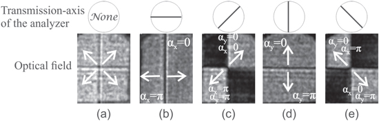
Figure 3. Irradiance of the experimental non-homogeneous vector field. (a) Without analyzer, and through an analyzer whose transmission axis is oriented at (b) σA = 0, (c) σA = π/4, (d) σA = π/2, and (e) σA = 3π/2 radians, respect to the x-axis.
Download figure:
Standard image High-resolution imageFinally, the amplitude filters were placed according to (3). The resulting optical field irradiance is shown in figure 4(a) while in figure 4(b) it is shown by the irradiance of the optical beam through the analyzer when it was oriented from 0° to 190° in steps of 10° or π/18 radians, the labels are indicated in degrees for better clarification. These figures demonstrate the conversion from a homogeneous linearly polarized beam into a radially polarized beam.

Figure 4. Radial vector field. Field irradiance (a) without analyzer and (b) through an analyzer oriented to several angles σA.
Download figure:
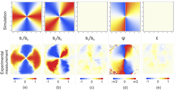
Standard image High-resolution imageTo quantify the polarization of the resultant beam, we performed a set of intensity measurements and calculated the Stokes parameters (S0 − S3) [41] at each point of the beam as figures 5(a)–(c) show. We derived the polarization ellipse parameters as  and
and  , where ψ is the local azimuthal angle, and
  is the ellipticity. This ellipse parameters are related with α and σ by
  and
and  . In figure 5(d) the experimental inclination map ψ is contrasted against the map of the azimuthal angle of the simulated beam. At the time, we found an average ellipticity of
  with a standard deviation of 0.102 rad, the simulated and experimental ellipticity map are shown in figure 5(e).
Figure 5. Polarization parameters distribution: simulation versus experimental measurements. (a)–(c) S1 to S3 normalized Stokes parameters of the resultant beam, (d) azimuthal angle and (e) ellipticity.
Download figure:
Standard image High-resolution image
4. Conclusions and remarks
In summary, in this paper, a simple and a practical experimental method was presented to convert a homogeneous linear polarized beam with TEM00 mode beam into a radial beam, which typically is interpreted as the sum of TEM01 and TEM10 modes. The polarization conversion was achieved by modulating the position and amplitude of two gratings in the input plane of a DACPI.
The main advantage compared to other interferometric techniques is the stability of the interferometric setup, and low cost of elements used. The polarization conversion method consisted of designing the gratings in which the desired phase-shifting correspond to the shifting position of each region of the space. Then filtering the first grating harmonic in the Fourier place. The theoretical model was validated by the experimental demonstration in figures 3–5. It is important to mention that one of the main disadvantages of the present method is the loss of beam power. Because of the DACPI, the optical field in the output plane is weighted by the constants c and d. Experimentally, the transmission efficiency between the input and output planes was measured to be 8.85%. However, we believe that it is possible to connect this idea of amplitude and phase modulation to another type of common-path interferometer that allows us to eliminate the use of at least one diffraction grating, improving the output power.
We emphasize that by the use of this technique it is possible to create a CVB by using gratings and amplitude filters printed in 'simple' materials as acetates. In this work, the generation of a radial beam was presented; however, other CVBs could be generated with this method, for example, an azimuthal beam. In that case, the gratings and amplitude filters of both orthogonal input optical fields would be interchanged. Actually, it would be possible to modulate the optical field to generate polarization states with different topological charges. With this method, we avoid the use of SLMs and specialized retarders. This idea could be very useful especially to the researchers or laboratories that are venturing into the use of cylindrical polarization that do not have the specialized devices that are commonly used. In the same way, this technique can also be used for educational purposes. This simple method achieved with optical elements of low cost allows its implementation in several applications where the cost is a very important limitation, or it is a factor for its commercialization.
Acknowledgments
This work was partially supported by Consejo Nacional de Ciencia y Tecnologia (CONACYT) under Grant 257853, by Vicerrectoria de Investigacion y Estudios de Posgrado (VIEP) of Benemerita Universidad Autonoma de Puebla (BUAP) under Grant 100425744-VIEP2019, and Direccion de Investigacion e Innovacion of Universidad de Montemorelos under Grant 2018-755.