


Abstract
The main emphasis of this article is to compare the heat transfer performance of two different nanofluids i.e. carboxy-methyl-cellulose (CMC) + water-based molybdenum dioxide (MoS2) nanofluid and kerosene oil-based molybdenum dioxide nanofluid during the fluid flow through a symmetric microchannel which is pumped by the mechanism of peristalsis and electroosmosis. The energy dissipated by Joule heating and viscous dissipation is also taken into account. An analysis of volumetric entropy generation is also conducted. Rabinowitsch fluid model is employed to characterize the shear-thinning behavior of CMC + water solution and Newtonian fluid properties of kerosene oil. The mathematical model for the problem is formulated by the Navier–Stokes, energy equation, and Buongiorno fluid model in combination with the Corcione model for thermal conductivity and viscosity of the nanofluid. Further, the Poisson–Boltzmann equation is utilized to compute the potential generated across the electric double layer. The homotopy perturbation technique is employed to compute the approximate solutions for temperature and nanoparticle volume fraction and exact solutions are obtained for velocity and the stream function. Salient features of the fluid flow are illustrated with the aid of graphical results. Contour plots for stream function are prepared for flow visualization. A comparison of heat transfer performance and entropy generation between both working fluids is presented. It is observed that aqueous solution modified by CMC and nanoparticles possess a higher heat transfer tendency and less entropy is generated in this case when compared with other nanofluid i.e. MoS2/kerosene oil nanofluid under the same physical conditions. It is further noted that fluid flow can be controlled by the strength of the applied electric field. Upon increasing electroosmotic parameters, there is a very minute rise in volumetric entropy generation in the case of MoS2/CMC + water nanofluid. However, there is a substantial rise in entropy generation for MoS2/kerosene oil nanofluid.
Export citation and abstract BibTeX RIS
Recommended by Dr Stefan Llewellyn Smith
. Nomenclature
| Symbols | Description | Unit |
|---|---|---|
| d | The radius of the pipe | m |

| Wavelength parameter | m |

| Wave amplitude | m |

| Radial and axial velocity component | m s−2 |

| The density of the nanofluid, base fluid, and nanoparticles | kg m−3 |

| Time parameter | s |

| Pressure field | N m−2 |

| Shear stress components | N m−2 |

| Local electric charge density | C m−3 |

| The axial electric field | kg m s−3 A−1 |

| Specific heat of the nanofluid, base fluid and nanoparticles respectively | J kg−1 K−1 |

| Temperature field | K |

| Brownian diffusion parameter | m2 s−1 |

| Concentration field | kg m−3 |

| Electrical conductivity of the nanofluid, base fluid and nanoparticles respectively | S m−1 |
 Ť
Ť
| Thermophoretic parameter | m2 s−1 |

| Nanoparticle volume fraction | [—] |

| Thermal conductivity of the nanofluid, base fluid, and nanoparticles respectively | W m−1 K−1 |

| The Boltzmann constant | J K−1 |

| The diameter of the base fluid molecule and nanoparticles respectively | nm |

| The freezing temperature of the base fluid | K |

| Dynamic viscosity | kg m−1 s−1 |

| Electric potential | V |

| The dielectric constant for vacuum | F m−1 |

| The relative permittivity of the fluid medium | [—] |
.

| The bulk concentration of ionic species | Kg m−3 |

| The local ionic density of cations and anions respectively | Kg m−3 |

| Charge of electron | C |
| z | Valence | [—] |

| Dimensionless pressure parameter | [—] |
| Re | Reynolds number | [—] |

| Helmholtz–Smoluchowski velocity | [—] |
| m | The Debye length parameter | [—] |

| The Eckert number | [—] |

| The pseudo-plasticity parameter | [—] |

| Amplitude ratio | [—] |

| Dimensionless stream function | [—] |
| Br | Brinkmann number | [—] |
| ΔT | Temperature difference parameter | [—] |

| The elastic tension parameter | [—] |

| The wall mass parameter | [—] |

| The wall damping parameter | [—] |

| Prandtl number | [—] |

| Dimensionless Brownian diffusion parameter | [—] |

| Dimensionless thermophoretic parameter | [—] |

| Thermal Biot number | [—] |

| The Joule heating parameter | [—] |

| Dimensionless zeta potential | [—] |

| Dimensionless volumetric flow rate | [—] |

| Dimensionless velocity components | [—] |
| θ | Dimensionless temperature | [—] |
| Φ | The dimensionless nanoparticle volume fraction | [—] |
1. Introduction
Thermal performances of the base fluids (water, engine oil, ethylene glycol, kerosene oil, carboxy-methyl-cellulose (CMC), methanol, and other heat transfer fluids) play a vital role in many thermal systems and, heating and cooling processes. However, the thermal conductivities of these base fluids are not sufficient for the better performance of various thermal systems. Nowadays, nanostructured material and carbon nanotubes have extensively been used for improving the thermal conductivity and other thermophysical properties of heat transfer fluids (Murshed et al 2009, Özerinç et al 2010, Solangi et al 2015, Gupta et al 2017). In most of the studies on the nanofluids, authors focused on the thermophysical properties of the nanofluids however the rheological properties of the nanofluids are equally important in dealing with the advancements of nanofluid dynamics. Considering the rheological importance of nanofluids, Hojjat et al (2011a, 2011b) have investigated the non-Newtonian nanofluids with the power-law model. They have prepared the non-Newtonian nanofluids using 0.5 wt%. An aqueous solution of CMC with the suspension of three types of nanoparticles terms as γ-Al2O3, TiO2, and CuO. They have concluded that the power-law index of nanofluids is less as compared to base fluids and it further diminishes with raising the nanoparticle volume fraction of the nanoparticles. However, the consistency indices of nanoparticles enhance with increasing the nanoparticle volume fraction. Inspired by the thermophysical and rheological properties of the CMC-based nanofluids, some theoretical and experimental investigations (Jia et al 2016, Saqib et al 2018a, 2018b, Al-Rashed et al 2019) on CMC-based nanofluids with various nanoparticles have recently been presented.
Kerosene oil is another heat transfer fluid that is widely used to prepare the nanofluids with the suspension of nanoparticles and is applicable in various thermal systems. The thermophysical and rheological behaviors of the kerosene-based nanofluids (Askari et al 2016) have been experimentally performed. An improvement in the convective heat transfer coefficient is noted as 66% at Reynolds number of 4553 and 0.3 wt% nanoparticle volume fraction. In the same patterns, some investigations on kerosene-based nanofluids (Yu et al 2010, Agarwal et al 2013, Arabpour et al 2018, Alkasasbeh et al 2019, Gul et al 2020) have recently been reported. Various types of inorganic nanoparticles (titanium dioxide, zinc oxide, magnesium oxide, gold, silver, etc) and organic nanoparticles (liposomes, dendrimers, carbon nanomaterials, and polymeric micelles) have been used to prepare the varieties of nanofluids. Molybdenum disulfide (MoS2) is another inorganic compound that can be used as nanoparticles with a unique feature that can reduce the friction coefficient and wear rate. An experimental work to examine the rheological and thermophysical properties of MoS2/oil-based nanofluids (Mousavi et al 2019) has been reported. It is observed that viscosity index has been increased by 5.39%, 6.71%, and 7.04% for 0.1%, 0.4%, and 0.7 wt% MoS2 nanoparticles respectively. Some other investigations (Gugulothu and Pasam 2019, Khan et al 2020a, Nadeem et al 2021) have also been added to examine the thermophysical properties with various base fluids and hybridized with other nanoparticles. Based on the better outcomes of the CMC-based nanofluids, kerosene-based nanofluids, and MoS2 nanoparticles, the present model is deliberated to examine the thermophysical and rheological effects on peristaltic pumping in the presence of electroosmosis.
Peristaltic pumping is an important mechanism of biomedical science which pumps the physiological and rheological fluids from one part to another part of the body/artificial systems without any contamination. A novel approach in order to combine the benefits of nanofluids and peristaltic pumping can make use in drug delivery systems (Tripathi and Bég 2014) and solar magneto-biomimetic nano pumps (Prakash et al 2019). With magnetohydrodynamics mechanisms, some peristaltic pumping models (Khan et al 2020b, Nadeem et al 2021b) with Newtonian nanofluids have been described. Viscous materials are defined based on Newton's law of viscosity. But, such materials do not represent realistic materials. Keeping this realistic role of rheological fluids, some mathematical models (Hussain et al 2019, Saleem et al 2021) on non-Newtonian nanofluids flow driven by the peristaltic pumping have been investigated. The effects of non-Newtonian parameters on pumping and flow characteristics have been analyzed.
The demands of research in the field of transportation and microelectronics, heating, and cooling processes have been changing due to the requirement of rapid outputs and cost-effectiveness. Due to challenging demands, microfluidics devices have been accomplishing great attention from researchers to fulfill the requirements. Microfluidics devices work on electroosmosis mechanisms. Electoosmosis is one of the significant phenomena, which means the relative motion of ions and electrolyte solutions under the effects of the applied electric field. This mechanism depends on the pH value and aqueous electrolyte. Due to net charges on the surface, an electric potential is generated which is known as zeta potential. With a combination of the nanofluids with electroosmosis mechanism, electroosmotic flows of the nanofluids in soft nanochannel (Zhao and Jian 2019), and in microfluidics channel (Ramesh et al 2019) have been studied. The effects of electric field and electric double layer (EDL) thickness have been computed. With add of peristaltic pumping, some interesting studies on nanofluid flow are driven by combined effects of peristaltic pumping, and electroosmosis has been reported (Prakash et al 2020, Akram et al 2020a, 2021) to extend the range of the applications. None of the studies have focused on the rheological effects on peristaltic pumping with electroosmosis mechanisms. Pointing out this gap of literature, most recently researchers have developed some models on non-Newtonian nanofluids (Prakash and Tripathi 2018, Jayavel et al 2019, Tanveer et al 2019, Akram et al 2020b) flow driven by the electroosmosis induced peristaltic pumping in which various types of rheological models such as pseudoplastic model (Jayavel et al 2019), Sutterby fluid model (Akram et al 2020b), Bingham model (Tanveer et al 2019) and Williamson fluid model (Prakash and Tripathi 2018) have been considered to analyze the rheological behaviors.
Nevertheless, entropy generation analysis has not been discussed in the above investigations, which is one of the mechanisms of thermodynamics introduced by Bejan. The performance of a thermodynamical system can be assessed by the entropy generation during the process. Entropy is basically the measurement of energy that is not available to do work or in other words, it is the amount of energy dissipated during the processing of a thermodynamical system and contributes to disorders of the system. The efficiency of the thermal devices can be improved by minimizing the entropy generated by viscous forces and the passage of the electric fields through the electrolyte solution. Various investigations are carried out by the researchers to inspect the entropy generation phenomenon. Entropy generation analysis is performed by Mehryan et al (2018) during the flow of ferromagnetic fluid through a square enclosure under the application of axial Lorentz force. An entropy generation analysis for blood flow through a multiple stenosis artery was investigated by Zidan et al (2021). Recently, another study for entropy generation analysis has been presented by Narla et al (2020) with electroosmosis, peristaltic pumping, and nanofluids. They have considered the curved channel to examine the curvature of the flow geometry. Furthermore, entropy generation analysis appears in some recent research papers such as analysis carried out by Hou et al (2021), Mekheimer et al (2021), Nadeem et al (2021b), and Rachid et al (2021).
Rabinowitsch fluid model is one of the pseudoplastic fluid models, which shows the shear thinning, shear thickening, and Newtonian behavior. In all the above investigations, none of them considered the Rabinowitsch fluid model. However, some of the authors have studied the peristaltic pumping of Rabinowitsch fluid (Sadaf and Nadeem 2017, Vaidya et al 2019) but electroosmosis mechanism and nanofluids have not been taken into considerations. It is worth developing a more generalized model to cover the (a) peristaltic pumping, (b) electroosmosis mechanism, (c) Rabinowitsch fluid model, (d) CMC + water based nanofluids, (e) kerosene-based nanofluids, (f) molybdenum disulfide (MoS2) nanoparticles, (g) symmetric microchannel, and (h) entropy generations in a single platform. The homotopy perturbation method (HPM) is employed to find out the approximated series solutions. In-house Mathematica code is employed to compute the graphical results. A depth discussion has been made for all results. The findings of the present model will serve in a wide range of applications in bio microfluidics, industrial engineering, and many cooling and heating systems. Moreover, they will also help in choosing a more suitable fluid for heat transfer applications.
2. Mathematical formulation
2.1. Flow regime
Here we examined the two-dimensional (2D) incompressible peristaltic pumping of nanofluids through a 2D symmetric microchannel. Two types of nanofluids are prepared by dispersing the spherical shaped molybdenum disulfide nanoparticles of average diameter 30 nm in two different types of base fluids i.e. kerosene oil, and CMC + water which is the solution of 0.3 wt% of CMC in water. Kerosene oil represents the Newtonian characteristics whereas CMC + water solution depicts the non-Newtonian shear thinning characteristics. The progressive sinusoidal wave of wavelength λ is propagated with constant speed c along the microchannel walls to engender the peristaltic propulsion. The peristaltic pumping is further mobilized by electroosmotic forces which are generated by applying the external electric source across the EDL. Cartesian coordinate system ( ,
,  ) is adopted to formulate the problem mathematically and the physical sketch of the symmetric microchannel is shown in figure 1 with
  being along the centerline and
  perpendicular to it. The mathematical form of the deforming microchannel walls is considered as:

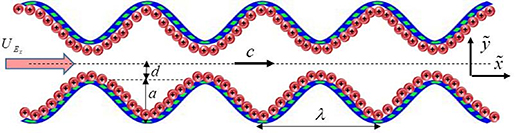
Figure 1. Schematic representation of the peristaltic pumping.
Download figure:
Standard image High-resolution imagewhere d is the half-width of the channel,  is the time and
  is the amplitude of the wave. Moreover,
  =
=  and
and  = −
= − show the position of the upper and the lower walls of the channel.
2.2. Governing equations and their scaling
In this investigation, Rabinowitsch fluid model is incorporated to specify the non-Newtonian aspects of CMC + water/MoS2 nanofluid as well as Newtonian properties of kerosene oil/MoS2 nanofluid by choosing a suitable value pseudo-plasticity parameter. The impact of the physical properties of particles and the base fluid is included through the Corcione model for thermal conductivity and viscosity of nanofluids, and the Buongiorno model for nanofluids is adopted to incorporate the Brownian and thermophoretic diffusion of nanoparticles in the fluid medium. It has been experimentally found that the solution of CMC + water with up to 6 wt% of CMC depicts the shear-thinning properties having the same thermophysical attributes as that of water. In this investigation, the solution of 0.3 wt% of CMC in water is considered. The electrostatic potential emerging due to applying an external electric field is modeled through linearized Poisson–Boltzmann ionic distribution. The additive aspect of Joule heating and viscous dissipation is also taken into consideration. The no-slip boundary conditions for velocity, convective boundary conditions for temperature, and condition of zero net mass flux at boundaries are enforced.
Subject to the above inferences, the momentum, energy, and concentration equations are derived as Akram et al (2020a), Shafey et al (2021):


where

Here  represents the velocity vector. The expression for the Rabinowitsch fluid model is given by:

In which  symbolizes the parameter of pseudo-plasticity and
  the effective dynamic viscosity of nanofluid. In the above relations,
  stands for pressure force,
  ,
,  and
and  are the extra stress components,
  is the effective density of nanofluid,
  is the thermal conductivity of nanofluid,
  and
and  are the specific heat capacity for nanofluids and solid particles respectively,
  and
and  are the parameters for thermophoresis and Brownian diffusion,
  is the effective electrical conductivity of nanofluids,
  is the electric body force,
  is the temperature and
  is the nanoparticle volume fraction.
The effective density and effective specific heat capacity defined by the general mixture rule are expressed as:


here, the subscript 'bf' stands for the base fluids and the subscript 's' designates the properties of solid nanoparticles.
The ratio for effective thermal conductivity and viscosity of nanofluids as predicted by Corcione is given as:

where  represents the nanoparticle volume fraction molybdenum disulfide nanoparticles,
  is the freezing temperature for base fluid,
  and
and  are the average diameter for nanoparticles and the molecule of the base fluid and
  is the Reynolds number for nanoparticles defined as:

in which  designates the Boltzmann constant. The electrical conductivity for nanofluid is calculated by Maxwell–Garnett model as:
The well-known Poisson equation is used to characterize the electric potential generated due to the mobility of excess of counterions in the vicinity of the EDL when an external source of electricity is applied as:

where  and
and  designate the relative permittivity for the base fluid and the permittivity of vacuum respectively and
  is the net electric charge number density with e being the charge of the electron, z is the net valency of ionic species and
  are the local ionic density of cations and anions respectively having bulk ionic concentration n0.
Introducing the dimensionless numbers to facilitate the non-dimensional analysis:


where Re, m, uhs, Nt, Ec, Br, S, Nb,  , E1, E2, E3, Pr,
  , and α portend the Reynolds number, Debye length parameter, electroosmotic velocity or Helmholtz–Smoluchowski velocity, thermophoretic parameter, the Eckert number, Brinkmann number, Joule heating parameter, the Brownian diffusion parameter, the dimensionless temperature, the elastic tension parameter, the wall mass parameter, the wall damping parameter, Prandtl number, the dimensionless nanoparticle concentration parameter, and the dimensionless pseudo-plasticity parameter respectively. For suitable values of the pseudo-plasticity parameter, Rabinowitsch fluid model represents dilatant (α < 0), Newtonian (α = 0), and pseudoplastic fluid (α > 0).
Using equation (15) into equations (2)–(7) and (14) and considering the assumption of creeping flow, i.e. the long wavelength and low Reynolds number approximations, the continuity equation is trivially justified and equations (3)–(7) and (14) are reduced to:


Introducing the Boltzmann equation for describing the local ionic density of each ionic species after inserting the expression for work done by the electric force on the ions,

and inserting it in equation (25) to obtain the Poisson–Boltzmann potential distribution, we get:

The Poisson–Boltzmann equation can be linearized for a small potential of up to 50–80 mV. In general, at room temperature and for a wide range of pH of the electrolyte solution, the standard value of generated potential is less than or equal to 25 mV. Therefore the approximation of low zeta potential is applicable for electroosmotic flow i.e.  and equation (23) is reduced to:

Enforcing the condition of the same potential generated at both walls as:

and integrating equation (24) for potential generated within the EDL which yields as:

The corresponding boundary conditions imposed along the microchannel walls in the dimensionless form can be written as:

where  represents the temperature Biot number.
The heat transfer rate at the wall is calculated as:

2.3. Entropy generation
The rate of volumetric entropy generation in the nanofluid flow produced by heat transfer, nanoparticles, electroosmosis, and fluid friction is given by:
The dimensionless entropy generation is the ratio between actual entropy and the characteristics rate of entropy generation  defined as:


where  and
and  are the dimensionless parameters defined in equation (15).
2.4. Solution methodology
Solving equation (16) directly subject to boundary condition given in equation (28) yields,

Inserting this relation in equation (20) and then solving it, by imposing boundary conditions described in equation (27), for the velocity field, we get the following expression for the velocity of the nanofluid
Integrating equation (34) subject to boundary condition Ψ = q/2 as y → h, we get
The nonlinear coupled equations (18) and (19) are executed by employing the homotopy perturbation technique subject to boundary conditions for temperature and nanoparticle volume fraction expressed in equation (28). The deformation relations for the considered problem about parameter qp are described as:

where the linear operator  is defined as
  . Here
  and
and  are the initial approximations for temperature and nanoparticle volume fraction respectively which are defined as:


Now expanding  and
and  in a series solution about small parameter q as:

Following the technique of HPM, the final solutions for temperature and nanoparticle volume fraction are obtained by setting qp→ 1 as:

And we get
3. Results and discussion
Physical understanding of the flow problem can be obtained by discussing the impact of various important parameters on the flow phenomenon. For this purpose graphical results for velocity, temperature, entropy generation, and heat transfer rate are prepared for both MoS2/CMC + water nanofluid and the MoS2/kerosene oil nanofluid subject to multiple values of the pertinent parameter. Further, the trapping phenomenon is analyzed by plotting the contours plots for stream function. The fraction of nanoparticles to be dispersed in both base fluids is chosen to be 0.06 vol%. The physical attributes of kerosene oil, CMC + water, and molybdenum disulfide nanoparticles calculated at an initial temperature of 298 K are listed in table 1. The Prandtl number for water and kerosene oil is calculated to be  and 22.8507 respectively using the thermophysical attributes given in table 1. Moreover, the dimensionless thermophoretic and Brownian diffusion parameters for MoS2/CMC + water nanofluid are found to be
  and
and  respectively and for MoS2/kerosene oil nanofluid they are
  and
and  respectively for initial nanoparticle volume fraction equal to 0.06.
Table 1. Thermophysical properties of CMC + water, kerosene, and MoS2 nanoparticles.
| Physical properties | MoS2 | Kerosene | CMC + water |
|---|---|---|---|
| Specific heat (C) | 397.21 J kg−1·K | 2090 J kg−1·K | 4179.6 J kg−1·K |
Density ( ) ) | 5060 kg m−3 | 783 kg m−3 | 997.1 kg m−3 |
Thermal conductivity 
| 904.4 W mK−1 | 0.15 W mK−1 | 0.613 W mK−1 |
| Particle diameter (d) | 30 nm |

| 0.385 nm |
Dynamic viscosity 
| — | 0.164 Pa s−1 | 8.9 Pa s−1 |
Electric conductivity 
| 2.09 × 10⁻⁴ S m−1 | 5 × 10⁻¹¹ S m−1 | 5.5 × 10⁻⁶ S m−1 |
3.1. Velocity profiles
Figures 2–5 are prepared to clarify the alterations in velocity profiles subject to development is electroosmotic velocity parameter, Debye length parameter, zeta potential, and wall elasticity parameters. The velocity profiles for both of the nanofluids are compared and it is found that under the same physical conditions, the velocity of MoS2/kerosene oil nanofluid is relatively lower than the velocity of MoS2/CMC + water. It is due to the shear-thinning aspect of the CMC + water solution which facilitates the motion of the fluid. The change in velocity profile for an increase in electroosmotic velocity is clarified in figure 2. From the definition of the electroosmotic velocity parameter, it is obvious that velocity produced by the phenomenon of electroosmosis is directly related to the strength of the electric field and negative values of this parameter correspond to the mobility of ions in the direction of the peristaltic wave. An increase in uhs in a negative direction physically implies the presence of a strong electric field which produces an enhancement in the velocity profile. It is evident from figure 3 that there is a substantial enhancement in the velocity for increment in the Debye length parameter. As there is an inverse relationship between the thickness of the EDL and the Debye length parameter m, a rise in m corresponds to a thinner EDL. The electric potential significantly enhances for a thin EDL which acts as the main driving force of the ions. Hence, electroosmotic velocity is regulated and an overall elevation in the velocity of the fluid is noticed. A similar enhancing response of velocity towards larger zeta potential is illustrated in figure 4. Figure 5 provides an insight into the extent of variation produced in velocity via larger wall elasticity parameters. As for the increase in the wall tension parameter, the speed of the peristaltic wave tends to grow therefore a substantial increment in velocity profile is observed. A rise in the wall mass parameter also boosts the fluid motion. However, an uplift in the wall damping parameter strengthens the viscous damping forces leading to a strong deceleration in the fluid velocity. Figure 6 reveals that a significant decline in the velocity of both nanofluids occurs when nanofluid are prepared with large fraction nanoparticles. Clearly, it is due to the higher viscosity of the inserted molybdenum dioxide nanoparticles.
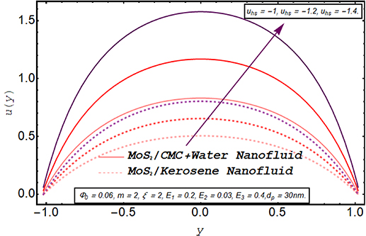
Figure 2. Axial velocity for electroosmotic velocity parameter.
Download figure:
Standard image High-resolution image
Figure 3. Axial velocity for the Debye length parameter.
Download figure:
Standard image High-resolution image
Figure 4. Axial velocity for zeta potential.
Download figure:
Standard image High-resolution image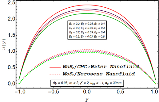
Figure 5. Axial velocity for wall parameters.
Download figure:
Standard image High-resolution image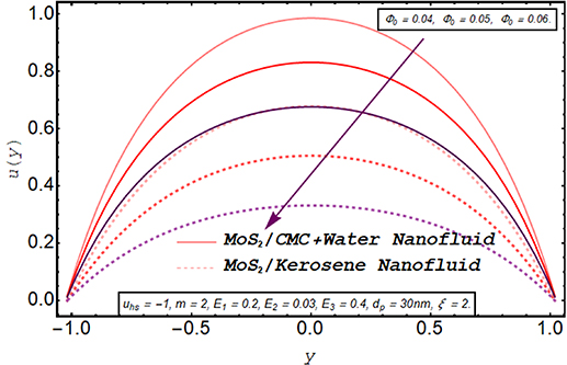
Figure 6. Axial velocity for nanoparticle volume fraction.
Download figure:
Standard image High-resolution image3.2. Trapping phenomenon
The streamline contours for the peristaltic transport in a microchannel are displayed in figures 7–12. The trapping phenomenon is observed for both types of nanofluids and it has been observed that fewer streamlines are circulated in the case of MoS2/kerosene oil nanofluid when compared with the streamline pattern of MoS2/CMC + water nanofluid. The trapping procedure is strongly retarded for an increase in the strength of the axial electric field and for a further increase in electroosmotic velocity, there is a substantial suppression in the size of the trapping bolus and the decrease in the number of circulating streamlines (see figures 7(a)–(c)). The trapping phenomenon for MoS2/kerosene oil nanofluid is similarly affected by the rise in the electroosmotic velocity parameter as shown in figures 8(a)–(c). The evolution in the circulatory flow pattern of the peristaltic flow regime for enhanced values of the Debye length parameter is inspected in figures 9(a)–(c) for MoS2/CMC + water nanofluid and in figures 10(a)–(c) for MoS2/kerosene oil nanofluid. A wider circular structure with a smaller inner bolus is observed for a smaller value of the Debye length parameter i.e. for a thick EDL for both nanofluids. However, for a gradual increase in values of m, there is an extension in the volume of the central circular structure and a decrease in the number of circulations is noticed. As for enhancement in both electroosmotic velocity and the Debye length parameter, fluid motion is accelerated and the fluid particles are forced to move rapidly along the straight paths producing a reduction in the rotatory flow pattern. Consequently, less number of streamline trapped bolus are observed. Streamline contours modification for variation in elastic wall properties are inspected through figures 11(a)–(c) and 12(a)–(c). It can further be observed that with growth in the wall tension parameter, the size of the central circulatory bolus shrinks. For increasing the wall mass parameter, an extension in the volume of the central zone is produced however straightening in the external streamlines also occurs. However, for modification in the wall damping parameter, a very minor alteration in streamline structure is noticed. Again for the larger wall tension parameter and wall mass parameter, the fluid velocity is augmented and fluid particles follow the laminar flow pattern. However, rising values of the wall damping parameter resist the motion of fluid therefore fluid particles are deflected to follow the rotatory path. Hence volume occupied by streamlines grows.
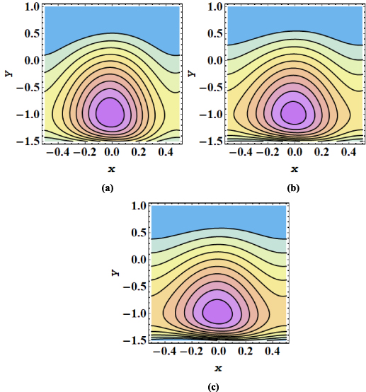
Figure 7. (a)–(c) Streamline patterns of MoS2/CMC + water nanofluid for (a) uhs = −1, (b) uhs = −1.5, and (c) uhs = −2.
Download figure:
Standard image High-resolution image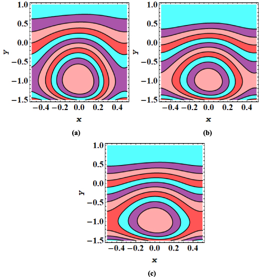
Figure 8. (a)–(c) Streamline patterns of MoS2/kerosene oil nanofluid for (a) uhs = −1, (b) uhs = −1.5, and (c) uhs = −2.
Download figure:
Standard image High-resolution image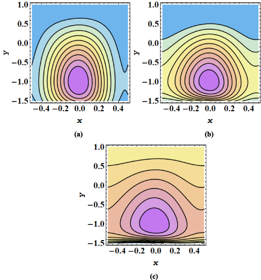
Figure 9. (a)–(c) Streamline patterns of MoS2/CMC +water nanofluid for (a) m = 1, (b) m = 2 and (c) m = 3.
Download figure:
Standard image High-resolution image
Figure 10. (a)–(c) Streamline patterns of MoS2/kerosene oil nanofluid for (a) m = 1, (b) m = 2 and (c) m = 3.
Download figure:
Standard image High-resolution image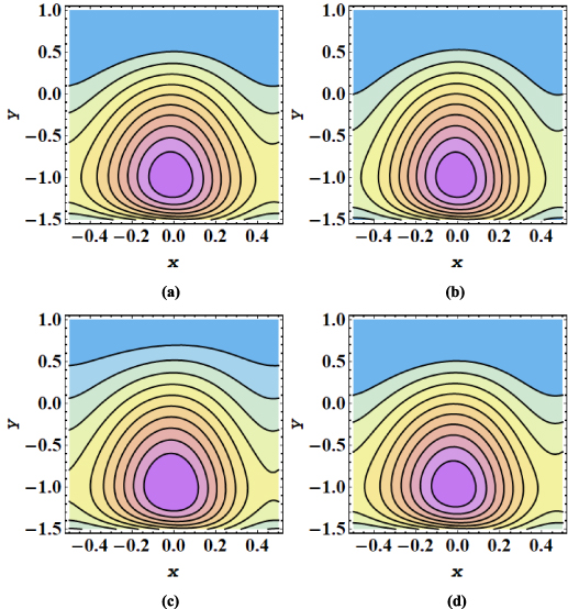
Figure 11. (a)–(d) Streamline patterns of MoS2/CMC + water nanofluid for (a) E1 = 0.2, E2 = 0.03, E2 = 0.4, (b) E1 = 0.4, E2 = 0.03, E2 = 0.4, (c) E1 = 0.2, E2 = 0.09, E2 = 0.4, and (d) E1 = 0.2, E2 = 0.03, E2 = 0.45.
Download figure:
Standard image High-resolution image
Figure 12. (a)–(d) Streamline patterns of MoS2/kerosene oil nanofluid for (a) E1 = 0.2, E2 = 0.03, E2 = 0.4, (b) E1 = 0.4, E2 = 0.03, E2 = 0.4, (c) E1 = 0.2, E2 = 0.09, E2 = 0.4, and (d) E1 = 0.2, E2 = 0.03, E2 = 0.45.
Download figure:
Standard image High-resolution image3.3. Temperature profiles
The evolution in axial temperature profile for Biot number, electroosmotic velocity parameter Debye length parameter, Joule heating parameter, and nanoparticle volume fraction is visualized in figures 13–17. A keen observation of these plots manifests that the temperature of kerosene oil nanofluid is comparatively larger than that of the temperature of CMC + water nanofluid. Due to the shear-thinning nature of CMC + water solution and less viscosity as compared to the viscosity of the kerosene oil, the acceleration of CMC + water nanofluid is notably higher than the speed of kerosene oil nanofluid. As a result, more cooling effect within the flow regime is produced by CMC + water nanofluid depicting a lesser temperature profile than kerosene oil nanofluid. Figure 13 elaborates on the alteration in the temperature of nanofluids via larger values Joule heating parameter. The temperature of the nanofluid is augmented when more electric energy is transformed into heat energy. It can be is visualized from figure 14 that there is a significant reduction in the temperature of both nanofluids as the Biot number is augmented. Biot number is directly linked with convective heat transfer. Increasing Biot number means that the thermal convection is boosted and the process of cooling occurs very rapidly. Consequently temperature within fluid medium drops. A consistent increment in the temperature profile is observed for enhancement in the electroosmotic velocity parameter (see figure 15). As increasing negative values of the electroosmotic parameter correspond to a rise in the strength of the aligned electric field which energizes the nanofluid particle. These energized particles contribute to raising the temperature of nanofluid. Furthermore, applying a strong electric field also boosts the joule heating phenomenon which is also a reason behind this increase in temperature. A substantial elevation in the temperature of the fluid for growing values of the Debye length parameter is demonstrated in figure 16. It is due to the higher potential generated across EDL which elevates the drag force produced by the rapid motion of ions on the fluid particles. The variation in the thermal profile of the fluid for inserting a larger fraction of nanoparticles is examined in figure 17. As expected, due to the growth in the conductive heat transfer, there is a reduction in the temperature of the nanofluid for a larger nanoparticle volume fraction. Consequently, the cooling effect of the working fluid is boosted.
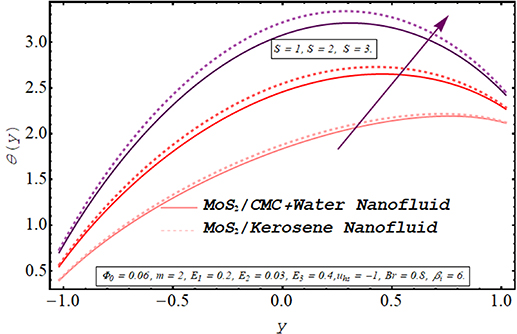
Figure 13. Temperature for the Joule heating parameter.
Download figure:
Standard image High-resolution image
Figure 14. Temperature for thermal Biot number.
Download figure:
Standard image High-resolution image
Figure 15. Temperature for electroosmotic velocity parameter.
Download figure:
Standard image High-resolution image
Figure 16. Temperature for the Debye length parameter.
Download figure:
Standard image High-resolution image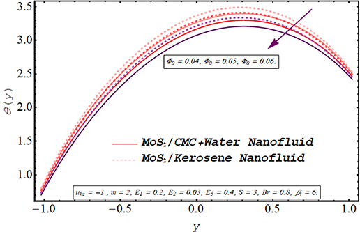
Figure 17. Temperature for nanoparticle volume fraction.
Download figure:
Standard image High-resolution image3.4. Heat transfer coefficient
The heat transfer characteristics for both nanofluids subject to alteration in diverse active parameters are analyzed in figures 18–21. The heat transfer tendency of both nanofluids i.e. MoS2/CMC + water nanofluid and MoS2/kerosene oil nanofluid is compared through graphical results. The heat transfer coefficient basically calculates the change in the temperature of the fluid on the flow regime. Evidently, the efficiency of MoS2/CMC + water in transferring the heat is higher than that of the MoS2/kerosene oil nanofluid. As mentioned earlier, the kerosene oil is more viscous than the CMC + water solution having a lower thermal conductivity than the thermal conductivity of CMC + water. Furthermore, under the same pumping power and applied forces, the motion of CMC + water is facilitated due to its shear-thinning aspects. All these properties of MoS2/CMC + water nanofluid are advantageous in raising its thermal efficiency. The evolution in the magnitude of the heat transfer coefficient for the multiple values of the Biot number is elaborated through figure 18. As enhancement in Biot number corresponds to the consistent growth in convective heat transfer, the cooling process is encouraged. As a result, the magnitude of the heat transfer coefficient increases. The alteration in the heat transfer coefficient for different values Joule heating parameter is delineated in figure 19. As the Joule heating parameter is connected with the strength of the axial electric field raised to power 2, increasing S physically means that a stronger electric source is connected. As a result, the phenomenon of electroosmosis is accelerated and the heat transfer rate rises. Rapid transmission of heat in response to a rise in the electroosmotic velocity parameter and the Debye length parameter is recorded through figures 20 and 21. Clearly, the pumping rate is increased by energizing the electroosmotic procedure which tends to raise the heat transfer due to convection. Consequently, the magnitude of the heat transfer coefficient rises.

Figure 18. Heat transfer coefficient for thermal Biot number.
Download figure:
Standard image High-resolution image
Figure 19. Heat transfer coefficient for the Joule heating parameter.
Download figure:
Standard image High-resolution image
Figure 20. Heat transfer coefficient for electroosmotic velocity parameter.
Download figure:
Standard image High-resolution image
Figure 21. Heat transfer coefficient for the Debye length parameter.
Download figure:
Standard image High-resolution image3.5. Entropy generation
Computing the amount of entropy generation is very important to get an insight into the efficiency of a working system. Higher the rate of generation of volumetric entropy, lower the efficiency of the system. Observation manifest that more entropy is generated by the flow of kerosene oil nanofluid however very less amount of energy is dissipated for CMC + water nanofluid. Figures 22–26 are prepared to visualize the alteration in the process of entropy generation for multiple values of the involved parameters. Decay in the amount of entropy generation is noticed for increasing values of the Biot number as observed through figure 22. As mentioned earlier Biot number is responsible for facilitating the transfer of heat due to convection producing a decline in the amount of entropy generation. An augmentation in entropy generation is noticed via increasing the Joule heating parameter through figure 23. As Joule heating is the amount of electric energy of ions utilized to overcome the resistance offered by the fluid medium to the passage of the electrons. A rise in the Joule heating parameter means that more resistance is experienced by ions which results in the enhancement of entropy generation. Insertion of more nanoparticles in both types of nanofluid increases their efficiency by enhancing their thermal conductance ability as evaluated through figure 24. A very minute rise in the entropy generation by MoS2/CMC + water nanofluid is observed at the center of the channel for larger values of both the electroosmotic velocity parameter and the Debye length parameter as seen through figures 25 and 26. However, a very significant elevation in entropy is produced in the case of MoS2/kerosene oil nanofluid.
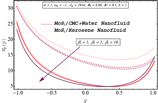
Figure 22. Entropy generation for Biot number.
Download figure:
Standard image High-resolution image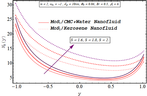
Figure 23. Entropy generation for the Joule heating parameter.
Download figure:
Standard image High-resolution image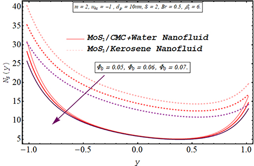
Figure 24. Entropy generation for the nanoparticle volume fraction.
Download figure:
Standard image High-resolution image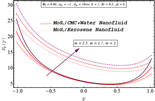
Figure 25. Entropy generation for the Debye length parameter.
Download figure:
Standard image High-resolution image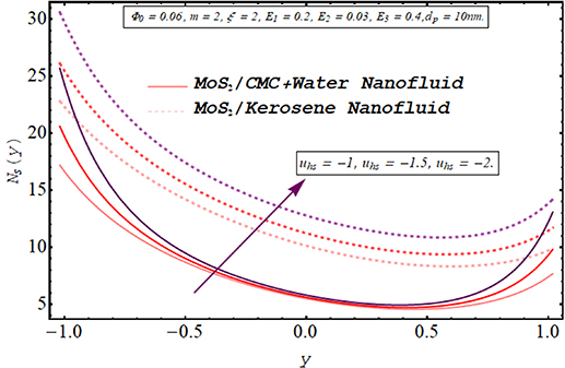
Figure 26. Entropy generation for the electroosmotic velocity parameter.
Download figure:
Standard image High-resolution image
4. Summary and conclusions
Here a comparative investigation is conducted to examine the heat transfer properties of two different types of nanofluids prepared with scattering molybdenum dioxide nanoparticles in kerosene oil and 0.3 wt% solutions of CMC + water. Various rheological characteristics are depicted by both types of nanofluids which are characterized by a single fluid model i.e. Rabinowitsch fluid model by using different values of the pseudo-plasticity parameter. Kerosene oil nanofluid exhibits the Newtonian characteristics where shear thinning aspects are represented by CMC + water-based nanofluid. Nanofluid flow is driven by electroosmosis as well as peristaltic pumping. The governing set of equations is reduced under the lubrication approach. The analytic expressions for velocity and the stream function are obtained directly. However nonlinear and coupled equations of energy and nanoparticle volume fraction are treated with the HPM. Furthermore, entropy generation during the fluid flow is also computed. It has been found that the heat transfer ability of CMC + water is higher than the thermal ability of kerosene oil. Moreover, entropy generated by the flow of kerosene oil nanofluid is much higher than in the case of CMC + water-based nanofluid. So, it can be concluded that MoS2/CMC + water is more suitable and efficient to be utilized in heat transfer devices and radiators. Additionally, the heat transfer rate is boosted by increasing the Biot number, electroosmotic velocity parameter, and the Debye length parameter. Further, fluid flow is controllable through the magnitude of the applied electric field. Analyses of the trapping phenomenon are also presented for both nanofluids. It has been found that the volume of the circulatory pattern is larger and the number of closes streamlines is lesser for kerosene oil nanofluid as compared with the trapping phenomenon of CMC + water based nanofluid. The findings of the present model can be utilized in developing various types of microfluidics pumping devices for use in microscale transport phenomena and especially in drug delivery systems.
Conflict of interest
On behalf of all authors, the corresponding author states that there is no conflict of interest.
Funding
This research did not receive any specific grant from funding agencies in the public, commercial, or not-for-profit sectors.