


Abstract
Dynamic and thermal characteristics of a turbulent and heated offset jet were numerically investigated using Ansys Fluent. The jet's heated bottom wall is mounted with a single square-section rib and characterized with constant heat flux. The flow velocity, at the nozzle exit, corresponds to a Re value of 39 000, besides the offset ratio is assumed to be fixed at 5. Nine different rib positions were tested in order to figure out which is the optimum one that enhances most the heat transfer. Detailed analysis of the development of the flow in addition to the convective heat transfer features is presented. The results showed that flow behavior changes significantly with the presence of the rib. Further, the heat transfer investigation revealed two optimum rib positions that guarantee the heat transfer amelioration.
Export citation and abstract BibTeX RIS
1. Introduction
Offset jet flows are considered as one of the most complicated flows, in terms of their dynamic and turbulent behaviors. Thus, they have been subjects of several numerical and experimental investigations, and still they are. As this particular type of flow is frequently found in several thermal and industrial systems, such as in the cooling and heating systems, the boiler's mixing process of the chambers of combustion, the evaporation process, in aircraft anti-icing systems and in several other applications, it seemed mandatory to investigate its thermal characteristics in order to ensure the optimization of the heat transfer.
In fact, the heat transfer enhancement is still also one of the most controversial problems that need to be solved in order to optimize the energy efficiencies and performances of thermal systems in many applications. Thus, for more than three decades, several scientific works have been conducted aiming the enhancement of the heat transfer, using wide variety of innovative techniques, among which we mention the deployment of ribs as roughness elements. This technique has been commonly used in practice in different applications such as refrigeration, cooling food and chemical industries... and it has proved its efficiency in improving the heat transfer. Hence, researchers nowadays still focus on the heat transfer amelioration in any present thermal application in order to reduce as maximum as possible heat losses with the insurance of an optimum enhancement of the heat transfers. Referring to this, the present research work aims to optimize the convective heat transfer in one particular flow application, which is Offset jet flow.
First, an offset jet is defined when the fluid is discharged from a nozzle, that is situated at a certain distance, h, from the horizontal plane and it has an offset ratio (OR) defined as the quotient of the offset distance by the nozzle width. Besides, it is characterized with the presence of a sub-atmospheric pressure region that promotes the deviation of the fluid from its initial direction towards the bottom wall. This is owing to the existence of a particular phenomenon called the 'Coanda' effect. The point at which the fluid attaches the wall is known as the reattachment point. This specific point is stagnant and characterized with maximum pressure value, figure 1(b). Further it delimits the first region, which is called the recirculation region, after which comes the impingement and the wall jet regions. In fact, due to the complicity of the offset jet flows, they are still extensively studied. With this intention, this work investigated not only the flow field characteristics but also the thermal behavior of a turbulent and two-dimensional offset jet. The investigated jet attaches a heated wall that is mounted with a square-section rib. Consequently, the effect of roughness element's presence on the flow and heat transfer behaviors will be examined.
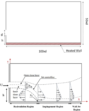
Figure 1. (a) Adopted geometry: 'no-rib case'. (b) Offset jet flow description.
Download figure:
Standard image High-resolution imageRegarding the deployment of ribs as turbulators that enhances the heat transfer, several scientific researches have been conducted. In this context, Lee and Abdel-Moneim (2001) studied numerically the heat transfer and the turbulent air flow behavior on a horizontal plate with two-dimensional transverse ribs with different pitch to rib's height ratios. This work has shown that the presence of ribs promotes a significant improvement in the heat transfer compared to a flat plate, also it predicted that the peaks of the local heat transfer coefficient coincide with the reattachment points downstream the ribs.
Similarly, Nakamura et al (2001) conducted an experimental investigation of thermal and hydrodynamic characteristics of a turbulent fully developed flow around a cubic obstacle located on a flat plate. Thereby, they predicted the average Nusselt numbers on each face of the cube as functions of Reynolds number for a Re < 2.104. Also, they managed to estimate the overall Nusselt number via this correlation: Nu = 0. 137.Re(0.68).
Furthermore, the experiments of Meinders et al (1999) has shown that the complex structure of the flow around a cube affects the local convective heat transfer. Which has been seen improved in the separation and reattachment zones. In contrast, in the recirculation zone the trapped vortex prevented the removal of the heat from the surface of the cube which caused a decline in the heat transfer coefficients.
Recently, Alfarwi et al (2017) based their experimental study on the hybridization of the ribs, which were deployed on the bottom surface of a rectangular duct of a turbulent fully developed air flow. In fact, they used three different geometries of ribs (semicircular, rectangular and hybrid). New correlations of Nusselt number, Darcy friction factor and efficiency index were obtained from this study. In addition, the configuration with hybrid ribs was found to give higher efficiency indices than the other cases ribs types.
As shown above, we may conclude that ribs have proved their efficiency when it comes to heat transfer enhancement. Therefore, it seemed important to investigate the ribs effect on the thermal behavior of a heated and turbulent offset jet. Among the very first studies on offset jet flows is Bourque and Newman's (1960) experimental investigation, in 1960. This work aimed to study the mean flow characteristics of an offset jet having different ORs. Throughout this study, the reattachment point positions were predicted separately for each OR. Further, Patankar et al (1977) solved numerically a three-dimensional turbulent jet flow field using the Reynolds Average Navier Stocks, RANS, method.
Moreover, an experimental investigation of a turbulent offset jet was conducted by Pelfrey and Liburdy (1986a) in order to examine the flow development behavior. A detailed description of the mean flow characteristics was provided, essentially in the recirculation region. These same authors, Pelfrey and Liburdy conducted a second experimental study (1986b), in which they investigated the flow's turbulence characteristics. This work's results proved the existence of a destabilizing and stabilizing effect of this flow, on the upper and lower sides respectively. In fact, the destabilizing characteristics intensifies the turbulence creation, that influences the root mean square values along the position of maximum jet velocity.
Additionally, Nasr and Lai (1997) investigated experimentally two parallel plane jets in the near field and a simple offset jet. Common flow characteristics were found for these two types of jets, for instance the presence of a recirculation region and the deflection phenomenon of the fluid towards the bottom wall. However, several dissimilarities were also reported, such as the fact that the recirculation region is considerably less elongated for two parallel jets compared to a simple offset jet flow.
Furthermore, in 1998 and throughout both numerical and experimental studies, Nasr and Lai (1998) confirmed that the enhancement of the two-dimensionality of the flow demands the use of side plates. The experimental results were used to judge which numerical turbulence model was the most adequate in modeling this two-dimensional offset jet. Ultimately, the Standard k- turbulence model proved its efficiency in predicting this flow. Moreover, it was found that the Reynolds number effect on the static pressure distribution when it exceeds 10 000.
Recently, several works of Baafour et al (Nyantekyi-Kwakye et al 2014, 2015, 2016), which are part of his thesis dissertation (Nyantekyi-Kwakye 2016), focused on the investigation of a three dimensional (3D) turbulent offset jet using the particle image velocimetry technique. In the first work (Nyantekyi-Kwakye et al 2014), a detailed analysis of the flow characteristics, essentially in the recirculation region, of a turbulent fully developed 3D offset jet was provided. Different OR were investigated. Consequently, it was reported that any increase of OR lead to an increase of the maximum streamwise mean velocity decay rate and influenced significantly the velocity and the turbulent kinetic energy (TKE) distributions within the recirculation region. Further, a two-point correlation analysis was performed to examine the flow behavior in details. This exam revealed the existence of large-scale structures, that seemed to get bigger as OR increased.
In addition, Baafour et al (Nyantekyi-Kwakye et al 2016)'s other work dealt with the examination of an offset jet flow over a surface mounted a square rib. This work aimed to investigate the rib position effect on the flow characteristics development. Among the results, it was reported that when the rib is located in the recirculation region, only the primary back-flow region, which is due to the fluid deflection, was noticed. However, when the rib was placed at the reattachment point or beyond, additional recirculation region appear that ameliorates the mixing process. Also, the mean reattachment point position moved further downstream when the rib position value increases.
The main target of the previously mentioned works was to understand the mean flow behavior on an offset jet, in terms of the velocity distributions and the turbulence features. Studying the thermal characteristics of this flow is equally important, as offset jets exist in several thermal industrial applications. In this regard, Holland and Liburdy (1990), studied experimentally a heated and turbulent offset jet attaching an adiabatic wall. Regarding the boundary conditions, constant nozzle exit temperatures and a Reynolds number of 15 000 were taken for different ORs. Through a comparison It was found that the heated flow reattachment point is indistinguishable from the unheated flow. There so, the buoyancy effect was neglected. Meanwhile, the temperature field measurements proved the dependence of the thermal behavior on the OR value, essentially near the wall region.
Another experimental study of a two-dimensional offset jet was conducted by Kim et al (1996). The fluid was ejected from a 20 mm width nozzle, the bottom wall is uniformly heated, the OR goes from 0 to20 and the investigated Reynolds numbers were in the range from 6500 to 39 000. Under these conditions, the flow's thermal and dynamic characteristics were examined, in order to determine the effect of each parameter and essentially the OR effect. The results showed that the reattachment point moves streamwise with the increase of the OR. Further, this work reported the existence of a secondary vortex, standing just at the left corner. In this region, the local Nusselt number presented an upward trend. Besides, it was found that the maximum Nusselt number coincide nearly with time-averaged reattachment point positions. Moreover, Kim et al (1996) correlated the local Nusselt number distribution to geometrical parameters through an empirical expression.
Recently, Gao et al (2015) examined the Reynolds number and the OR effects on the measurements of the convective heat transfer coefficient for a planar offset attaching jet. The results showed that the local heat transfer coefficient, from the wall to the jet, presented a peak that coincides with the reattachment point. Also, it was found that the heat transfer coefficient decreases with the offset distance, for a giving Reynolds number.
Hnaien et al (2017), conducted a numerical study on the heat transfer behavior of turbulent offset jet combined to a wall jet. Two different thermal boundary conditions at the bottom wall were tested: a constant wall heat flux and a constant wall temperature. This study revealed the efficiency of the standard k-ω turbulence model in the resolution of this particular flow. Besides, two parameters, Re and the bottom wall inclination, were examined in order to figure out their effects on the heat transfer process and to correlate them to several thermal characteristics, such as the average and local Nusselt number and heat flux. This study showed that the heat transfer was more intense for low inclination angles. Besides the convective heat transfer was enhanced with the increase of the Reynolds number.
More recently, Ajmi et al (2019, 2020) conducted numerical investigations of an oblique offset jet. The first work (Ajmi et al 2019) reported the effect of different parameters, Re, OR and the inclination angle, on the dynamic behavior of this particular flow. On the other hand, in (Ajmi et al 2020) they examined both dynamic and thermal behavior as function of the three previously mentioned parameters. Detailed analyses of the flow field, turbulent and heat transfer characteristics were shown. Additionally, different triple-parameters correlations governing Nu values in different flow regions were developed for the first time.
After the exposition of several scientific research that dealt with the deployment of ribs, as a heat transfer enhancement technique, and with offset jet flows it seemed interesting to blend these two field in one work. Also, it is true that the offset jets have been extensively studied throughout a long period. However, just a few works investigated the presence of obstacle in a turbulent offset jet. Owing to this fact, it seemed mandatory to investigate this particular flow with rib deployments and to see how it would behave under this additional geometrical condition. In fact, the majority of industrial applications of offset jets includes non-plane surfaces to which attaches the flow, for instance: air/fuel jets in combustion chambers and air jets for cooling electrical equipment.
Consequently, throughout this paper, a turbulent and two-dimensional offset jet is investigated. The jet impinges a heated surface, which is mounted a square-section rib. The scope of this present work is to optimize the heat transfer between the cold ejected fluid and the hot surface. There so, different rib positions will be tested in order to visualize their effect on the flow development and the convective heat transfer. Finding an optimum rib position is the ultimate purpose of this work. A schematic diagram of the investigated configuration is shown in figure 2.

Figure 2. Boundary conditions details.
Download figure:
Standard image High-resolution image2. Method
2.1. Adopted configuration
During this work, we inspired the investigated geometry from Kim et al's (1996) experimental work, represented in (figure 1). The air was ejected from a two-dimensional nozzle, having dimensions of 800 mm × 20 mm (L × d) which gives an aspect ratio, A = L/d, of 40 and proves the two-dimensionality criteria of the flow. Besides the lower wall is subjected to a constant heat flux, 1951 W m−2, and mounted with a rib, having a square section (20 mm × 20 mm). Hence, the chosen domain dimensions proved no effect on the flow development and behavior.
Figure 1 represents the 'no-rib' case, which is used to validate our numerical code, in terms of the mesh type and size and the turbulence model choices. h is defined as the offset distance and d as the nozzle width.
2.2. Hypothesis
The RANS equations are written and solved in the Cartesian (Ox, Oy) coordinate system, with the adoption of these following working hypothesis:
- The flow is considered turbulent and fully developed.
- The air is the working fluid.
- The heat flux is assumed to be constant all along the bottom wall.
- The flow is stationary and two-dimensional.
- The air is ejected in the longitudinal direction.
2.3. Governing equations
The averaged mass conservation, momentum and energy equations, of an incompressible fluid, are expressed in their general form in a Cartesian coordinate as follows:


Equation (2), presents an additional term that reflects the effect of turbulence: It is the Reynolds stress constraint. This constraint must be modeled in order to close equation (2). By exploiting the Boussinesq approximation, a relationship between the shear stress and the mean velocity gradient appears as follow:

Thus, for the closure of the whole equations system, four turbulence models, standard k-ω, SST k-ω, RNG k- and Realizable k- were tested. Only the SST k-ω turbulence model proved its accuracy in resolving this flow. A comparison test will be presented in the results section in order to highlight that the SST k-ω model presented the best results compared to the other models, (figure 4). Actually, the SST k-ω combines between the standard k- model in the near-wall region and the standard k-ω model in the far field region, which gives more consistent results and overcome the limits of each model used separately. In fact, to blend these two models, two blending function F1 and F2 were used. In this case the transport equations of k, the turbulent kinetic energy, and ω, the specific dissipation rate, are given as follows:


The generation of turbulence kinetic energy is modeled with the term  , while Gω represents the generation of ω.
  and
and  represent the effective diffusivity of k and ω, respectively, which are calculated as described below. Yk and Yω represent the dissipation of k and ω due to turbulence. Dω term represents the cross-diffusion term while Sk and Sω are the user-defined source terms.
Returning to the effective diffusivity, it is modeled as follows:


The SST turbulence model details are found in Ansys Fluent user guide (2013).
2.4. Grid distribution and boundary conditions
On the first hand, the boundary conditions, figure 2 gathers all the different used boundary conditions with their physical significations. As for the emission conditions, a uniform velocity profile was applied at the nozzle inlet, U0 = 28.47 m s−1, with a constant turbulence intensity of 0.01% and a Reynolds number of 39 000, (Kim et al 1996), which was calculated based on the nozzle width. Meanwhile, the turbulence dissipation rate, ω, was estimated basing on the hydraulic diameter as a length scale parameter. With regards heat flux, as it was assumed to be constant and applied uniformly on at the channel's base.
On the other hand, the choice of the mesh size and form is a mandatory phase to valid in order to guarantee a credible resolution of our problem's governing equation. As the geometry is not complicated, we adopted a quadratic non-uniform mesh. We ensured that the grid is enough fine in the vicinity of the jet nozzle, in the near rib-region and the heated bottom wall, and a quasi-loose elsewhere. Figure 3 represents a caption of the mesh distribution near the rib. As it is shown in figure 3, the mesh is well refined near the rib and gets coarser moving downstream and upstream.

Figure 3. (a) Mesh caption; (b) mesh around the rib.
Download figure:
Standard image High-resolution image3. Results and discussion
3.1. Validation phase
As the work was purely numerical, it was mandatory to validate the numerical CFD software we used, in terms of its reliability of the resolution of such flows. There so, comparisons between numerical results and experimental ones, of (Kim et al 1996), will be presented in this section.
The first step is to choose the adequate mesh type and size that gives an accurate resolution of the flow behavior. There so, figure 4 demonstrates the comparison between the numerical results of three different meshes against the experimental data of (Kim et al 1996), at three OR values. These meshes were assigned respectively as Mesh1, Mesh2 and Mesh3 each having 11 875, 33 600 and 52 332 non- uniform and quadratic cells. Refereeing to figure 4, we may see that Mesh1 presents huge error compared to the experimental values, especially for OR equal to 6.5 and 7. Meanwhile, Mesh2 and Mesh3 give approximately the same Nusselt pattern, that nearly coincides with the Nusselt experimental profile. There so, Mesh2 is adopted in the rest of the work, as it offers enough accurate resolution of this problem, and any increase of the mesh size would not have a significant amelioration effect on the predicted results. In fact, Mesh2 precision was found to be up to 97%.
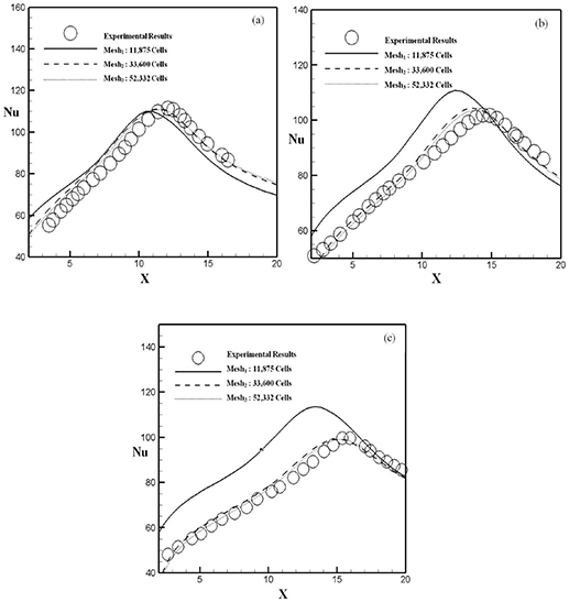
Figure 4. Boundary conditions details. Mesh sensitivity test; (a): OR = 5, (b): OR = 6.5, (C): OR = 7.5, Experimental results. Reprinted from [17], Copyright 2015, with permission from Elsevier.
Download figure:
Standard image High-resolution imageIn addition to the mesh size choice, knowing the most reliable turbulence model was equally important. In this context, four different models were tested. This second validation phase was conducted to prove the efficiency of one particular turbulence model in the resolution of such a flow. In fact, with the adoption of the same emission conditions of (Kim et al 1996)'s experimental work and for a constant OR, at 7,5, we tested four different turbulence models: RNG k-, Realizable k-, Standard k-ω and SST k-w.
On the first hand, figure 5 highlights the precision of the SST k-ω in the detecting of the local Nusselt values, at the bottom wall, compared to all the other three models. Actually, as it was previously mentioned, in the 'Governing Equation' section, this particular model blends between the Standard k-ω and the Standard k- turbulence models, which makes it more reliable. On the other hand, this figure demonstrates Fluent's capability to solve this problem, as the numerical results error does not even reach 3%. Basing on these results, the SST k-ω is used to conduct the rest of the simulations.

Figure 5. Turbulence model choice, Experimental results (Gao et al 2015). Reprinted from [17], Copyright 2015, with permission from Elsevier.
Download figure:
Standard image High-resolution imageOverall, the SST k-ω turbulence model and a non-uniform mesh, of 33 600 quadratic cells, will be used to solve numerically the dynamic and thermal behavior of this flow.
3.2. Mean flow structure
In this section, a detailed analysis of the rib position effect on the flow development and on the mean flow structures is presented. As it is previously mentioned, the investigated configuration is demonstrated in figure 3, in which stands a rectangular rib on the heated bottom wall. For all the numerical simulations, the OR was maintained at 5 while the Reynolds number was fixed at 39 000, similarly to Kim et al (1996) experimental work. However, the rib's position was the only varying parameter.
Actually, 9 different rib positions were tested and investigated. The rib position, Xrib, is expressed as follow:

Having xrib as the obstacle first edge position and xrp0 as the reattachment point for the no-rib case. In addition, the dimensionless reattachment point position, Xrp0, was found to be 11.3. Table 1 gathers all the tested cases.
Table 1. Rib positions.
| Case n° | 1 | 2 | 3 | 4 | 5 | 6 | 7 | 8 | 9 |
| Xrib | 0 | 0.25 | 0.5 | 0.75 | 1 | 1.25 | 1.5 | 1.75 | 2 |
In order to visualize the flow pattern for these different cases, the downstream velocity (U) contours and stream traces were plotted. First, figure 6 demonstrates the flow development for the four first cases. At a first sight, we may say that the rib presence changes significantly the dynamic behavior of this flow.

Figure 6. Velocity contours and stream traces; (a): Xrib = 0, (b): Xrib = 0.25, (c): Xrib = 0.5 (d): Xrib = 0.75; Red DOTS: Reattachment points; Grey DOTS: Xrp0.
Download figure:
Standard image High-resolution imageFor Xrib = 0, stand two different sized and counter-rotating vortices. The first one lies just above the top of the rib, having a counter-clockwise rotation direction. Meanwhile, throughout the rest of the recirculation region stands the main clockwise rotating vortex that extends to almost Xrp0, the same reattachment point as the 'non-rib' case.
However, for Xrib = 0.25, three vortices were found to be present. It is like that the obstacle divided the recirculation region into two regions with comparable sized counter-rotating vortices, that lie in the upstream and downstream rib areas. Further an additional horse-shoe vortex, the smallest one, stands on the top of the obstacle. It is important to mention that the final reattachment point position moves further downstream when Xrib = 0.25 and reaches a value of Xrp = 12.3, which makes the downstream vortex more elongated compared to the upstream one.
Figure 6(c) demonstrates a totally different behavior of the flow essentially in the recirculation region, for Xrib = 0.5. This figure shows the presence of two counter-rotating vortices, having different pattern. The first vortex occupies almost one third of the recirculation region, having a counter-clockwise rotation direction and lies from the nozzle-wall to the rib's upper surface with a high of around H/2. The second vortex is a double-centered, having a deflection point at the rib's right edge position. Even the huge effect of the rib presence, the reattachment point position returns to coincide, almost, at Xrp0. For this case, it was found that the negative velocity values and region are minimum compared to the previous cases.
Regarding Xrib = 0.75, the flow pattern changes again and presents three distinguishable vortices. The main one is situated between the nozzle wall and the first edge of the rib. This vortex is the most elongated and characterized with the most negative velocity values and with a counter- clockwise direction. Further the fluid attaches the upper edge of the rib at Xrp inferior to Xrp0. The other two vortices bounded the rib from both sides, left and right. The flow development downstream the rib is similar to a flow behavior facing a step. Hence the vortex attaches the heated wall at a position of Xrp = 11.1, which is slightly less than Xrp0. Figure 7 represents also the velocity contours and stream-traces corresponding to the rest of the rib location cases, Xrib in the range from 1 to 1.75. First for Xrib = 1 and Xrib = 1.25, the flow development behavior is similar to a flow facing step behavior, in which two distinguishable vortices upstream and downstream the rib is present. Actually, for these two cases, the fluid attaches the heated wall at the first facing edge of the rib. However, the recirculation region for Xrib = 1.25 is more elongated compared to Xrib = 1. Regarding the downstream vortices, they have almost the same dimensions.

Figure 7. Velocity contours and stream traces; (a): Xrib = 1, (b): Xrib = 1.25, (c): Xrib = 1.5 (d): Xrib = 1.75; Red DOTS: Reattachment points; Grey DOTS: Xrp0.
Download figure:
Standard image High-resolution imageRegarding the last two rib positions, the flow development is significantly different from the other cases. Hence, figures 7(c) and (d) highlight the existence of, considerably large, two co-rotating vortices. The first one stands in the recirculation region, having a reattachment length equal to Xrp0 which means that the rib presence has no longer effect on the development of the pre-attachment region. The second one extends from the upper rib edge to X = 30 and X = 37, respectively for Xrib = 1.5 and Xrib = 1.75, which gives dimensionless attachment lengths, Le, of 12 and 16 respectively. There so, we may say that Le increases the downstream movement of the rib when Xrib ⩾ 1. Because it was found to be 2 and 2.8 for Xrib = 1 and Xrib = 1.25, respectively.
3.3. Turbulence structures
In this section, a qualitative and detailed presentation of the turbulent kinetic energy for all the range of the rib positions is communicated in figures 8 and 9. The first four captions show the TKE distributions for Xrib going from 0 to 0.75. At a first sight, we see that the TKE contours change significantly with the variation of the rib position, we adopted the same scaling system for all the cases.
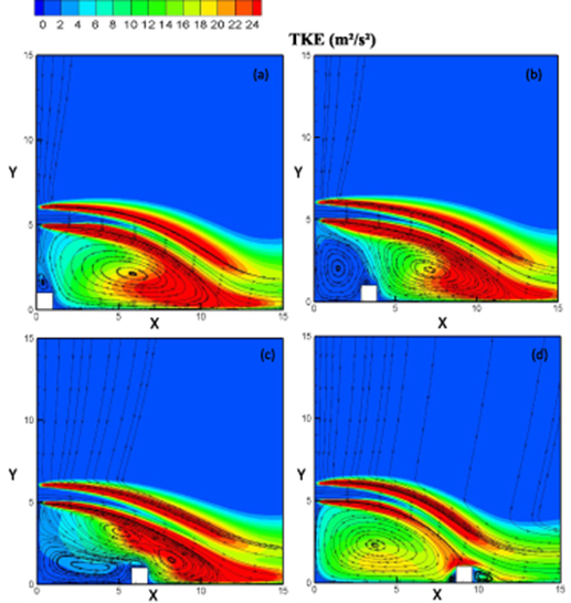
Figure 8. TKE contours and velocity stream traces; (a): Xrib = 0, (b): Xrib = 0.25, (c): Xrib = 0.5 (d): Xrib = 0.75.
Download figure:
Standard image High-resolution image
Figure 9. TKE contours and velocity stream traces; (a): Xrib = 1, (b): Xrib = 1.25, (c): Xrib = 1.5 (d): Xrib = 1.75.
Download figure:
Standard image High-resolution imageFigures 8(a)–(c) represent qualitatively almost the same phenomenon and distributions. In fact, for these cases, the upper and lower shear layers correspond to high TKE, which is predictable because of the presence of important friction forces that bound the potential core. Further, the counter-clockwise rotating vortices are characterized with the lowest TKE, unlike the main vortex, which is resulted from the fluid recirculation, that is characterized with higher TKE that increases in the downstream direction till the reattachment point. From which, it gets on decreasing.
However, for Xrib = 0.75, the maximum TKE appear to coincide with the rib position because the fluid attaches the wall just at the left upper limit of the rib. Elsewhere, in the recirculation region a progressive increase of TKE is seemed, which is contrary its behavior starting from the attachment position of the downstream rib vortex, that presents a sudden reduce in the TKE due to the fluid blocking.
Hence, figure 9 represents the TKE contours for the rest of the examined cases. The first two captions show nearly the same TKE distribution, that gets in increasing throughout the recirculation region till the reattachment point, from which it returns to decline due to the presence of the downstream rib vortex.
Meanwhile, figures 9(c) and (d) demonstrate the rib presence effect on the TKE's cartography when it is placed in the impingement region. All along the recirculation region the same phenomenon was seen, compared to figures 9(a) and (b). However, downstream the rib the minimum TKE's values' area gets elongated
Examining the mean flow structures and the TKE distributions can be related to the heat transfer behavior of this particular flow. So, we may relate the thermal characteristics ultimately to the dynamic features and expressions of the flow. Hence, after passing the first phase that deals with the overall flow hydrodynamic response, an investigation of the heat exchange phenomenon comes after in the next sections.
3.4. Heat transfer characteristics
The main purpose of this present work is the optimization of the convective heat transfer of a turbulent offset jet, with the use of a rib mounted on the heated-bottom wall. There so, 9 different rib positions were tested in order to figure out the optimum one, in terms of the amelioration of the heat exchange between the heated wall and the cold fluid. Hence, a detailed thermal analysis is presented, in this section, throughout the exploration of the local Nusselt number, Nux, paces and the temperature contours.
As a first step, the local Nu distributions are presented in figures 10–12, from which comparisons of the heat transfer performance are demonstrated for all the range of Xrib. In fact, the Nux were plotted against the 'no rib' case Nux, to see if the used Xrib enhances the heat transfer or do not. These figures illustrate how the Nu paces change significantly with the variation of Xrib. Actually, it is obviously seen that for each three successive rib positions the Nu pace presents a different shape. Regarding the temperature contours, the same scaling system is adopted for all the captions.
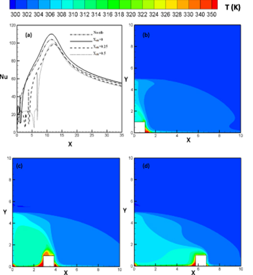
Figure 10. (a) Local Nusselt distributions, (b)–(d) temperature contours for Xrib = 0, Xrib = 0.25 and Xrib = 0.5.
Download figure:
Standard image High-resolution imageFirst, for Xrib between 0 and 0.5, figure 10(a) shows that the local distributions of Nu, calculated on the heated bottom wall, reflect almost a common shape with the no-rib case Nu pace, essentially in the post-reattachment region and they peak nearly at the same position, which is found to be the reattachment point position where stands the largest TKE value, figure 8, that intensifies the heat transfer phenomenon. Despite this similarity, a noticeable difference is detected near the rib area, where Nu was found to increase slightly and reach a certain local peak, from which it drops till a local minimum that corresponds to the first facing edge. In fact, at both left and right sides of the rib, different Nu values were detected that correspond to different temperatures presented in figures 10(b)–(d). This fact is owing to the near-rib vortices that prevent hot fluid, at the wall lowest limit, from exchanging heat with the colder fluid by blocking it. So, every increase of Nu, in figure 10(a), is equivalent to a decrease of the superficial detected temperature in figures 10(b)–(d).
Moreover, figure 10(a) highlights that only Xrib = 0, provides a slight enhancement in the heat transfer coefficient. Consequently, when a rib is placed at Xrib = 0.25 or Xrib = 0.5, the convective heat transfer gets less intensified and this is owing to the existence of considerably large counter- clockwise rotating vortices, in the recirculation region, which blocks the hot fluid from communicating with the colder fluid. However, throughout the rest of the recirculation region, Nu increases in the downstream direction till the reattachment point, from which it changes the variation trend.
On the other hand, for 0.75 < Xrib < 1.25, the Nu distributions, in figure 11(a), have shown a dramatic change compared to the no-rib case, in terms of their variation trends. For all these cases the flow attaches the wall around the rib positions, Xrib, as it was described above. Overall, from the nozzle wall up to Xrib, Nu presents an upward trend that decreases in intensity with the downstream movement of the rib. After that, Nu decreases, due to the presence of a small vortex standing just upstream the rib, which reduces the amount of the exchanged heat flux to a local minimum situated at the lowest part of the first facing edge. However, on the same edge appear different values of Nu, that correspond to different temperature values in figures 11(b)–(d), including the global maximum value, as the flow attaches the wall around Xrib with a greater TKE that enhances the heat transfer phenomenon. All along the rib's upper and right edges, Nu declines significantly and hit a local minimum value and then it returns to rise once again up to the attachment point of the rib's downstream vortex. In fact, when the fluid passed the rib, it is like the behavior of an offset jet flow, which explains this behavior. Finally, in the impingement and wall jet region the heat transfer gets in decreasing in the (OX) direction.
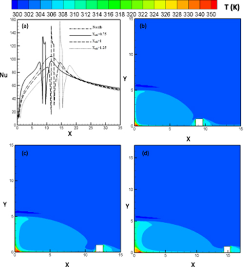
Figure 11. (a) Local Nusselt distributions, temperature contours: (b): Xrib=0.75, (c): Xrib=1, (d).
Download figure:
Standard image High-resolution imageRegarding now the effect of the rib presence, figure 11 provides all the information about the performance of each case separately. Starting from the nozzle wall to Xrib, only when Xrib = 0.75 the convective heat transfer is enhanced, meanwhile for the remaining cases the local Nu distributions were found to be underneath the local Nu distribution for the no-rib case, which is not the case in the downstream rib area. Furthermore, the global maximum convective heat transfer coefficient climbs with Xrib. In the impingement and wall jet regions, no considerable amelioration is noticed.
Concerning the last three positions, in which the rib is placed far away downstream the recirculation region, figure 12 represents similarly the local Nu distributions in addition to the temperature contours corresponding to investigated Xrib. Once again, the Nusselt patterns have remarkably changed, compared to the other Xrib and the no-rib case. However, the Nu variations seem to have the same paces, qualitatively, in all the range of Xrib between 1.25 and 2, in other words when the rib is located in the development region.
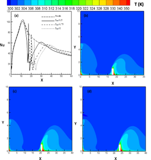
Figure 12. (a) Local Nusselt distribution, temperature contours: (b) Xrib = 1.5, (c) =1.75 (d): Xrib = 2.
Download figure:
Standard image High-resolution imageA similar behavior of all the local Nusselt distributions appears between the nozzle wall up to the reattachment points, which is owing to the rib's emplacement that has no effect on the flow development in the recirculation region, as described above. Furthermore, in this region, no heat transfer amelioration has resulted from the rib use. In fact, when the cold air passes the recirculation region, a dramatic fall of the Nu looms up having a slope that decreases in intensity with the downstream movement of the obstacle. This increase makes it up to the first rib facing edge, on which different Nu and temperature values were detected for the same reasons as the previous cases. Just after passing the rib, and all along the clockwise rotating downstream rib vortex, the heat transfer coefficient gets in increasing and peaks around the attachment point, Le, just as the behavior of a typical offset jet. Even though, according to the comparison with the no-rib case, facts have shown that this range of Xrib provides no heat transfer amelioration, with the exception of the attachment position at which the local Nu distributions were found to be slightly above the Nusselt (Nu) distribution for the no-rib case.
So far, the convective heat transfer has been found enhanced in some cases and in some local positions, there so a call to averaged and maximum parameters would be useful in order to judge which is the optimum rib position that offers the heights amelioration rate. Hence, averaged and maximum Nusselt numbers are question of comparison in this section. As for the maximum Nu, figure 13 demonstrates comparisons between the no-rib case and the other investigated cases. The examination of this characteristics would give information about the maximum exchanged convective heat transfer in each case and its location, see figure 14.
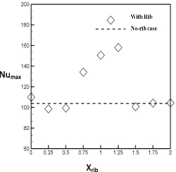
Figure 13. Maximum Nusselt values.
Download figure:
Standard image High-resolution image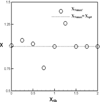
Figure 14. Maximum Nu values positions.
Download figure:
Standard image High-resolution imageThe maximum Nusselt value, in other words the heat transfer coefficient h, is found to be enhanced considerably for Xrib = 0.75, Xrib = 1 and Xrib = 1.25. Moreover, this amelioration rises with the downstream movement of the rib and gets 29%, 45% and 52% of the maximum no-rib case coefficient respectively. The determination of the position of these maximum values is equally important. That is why the dimensionless Numax positions, XNumax' = XNumax/Xrp0, were plotted against the rib position in figure 14. This figure highlights the fact that Numax appears around Xrp0, except for Xrib = 0.75 and Xrib = 1.25, where Numax position coincides with Xrib. In fact, these locations are characterized with the maximum TKE that intensifies the heat transfer and makes it maximum.
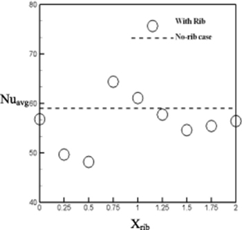
However, in order to get the appropriate choice of which Xrib gives the best heat transfer, the averaged heat transfer performance was examined. Therefore, figure 15 reveals comparisons between the averaged Nu values obtained for each case. Obviously, only the fourth and the fifth Xrib guaranteed a heat transfer enhancement with just above 9% and around 4%, respectively, compared to the averaged heat transfer coefficient of the no-rib case.
Figure 15. Averaged Nusselt values.
Download figure:
Standard image High-resolution image
Accordingly, the adequate choice of the optimum Xrib depends on the application's aim. If the target is the get a maximum local heat transfer, then Xrib = 1.25 would be the appropriate choice as it provides the maximum heat transfer coefficient. Otherwise, Xrib = 0.75 would be the chosen rib position as it offers the optimal overall averaged convective heat transfer performance.
4. Conclusion
This present work investigates the flow field development and the heat transfer characteristics of a two-dimensional and turbulent fully developed offset jet. The bottom is mounted a square-section rib and subjected to a constant heat flux. The rib position was varied in order to figure out which position assures the best heat exchange between the cold fluid and the hot wall. The flow velocity, at the nozzle exit, corresponded to a Re of 39 000, besides the OR was assumed to be fixed at 5. Nine different rib positions were tested.
Referring to the flow field distribution, the TKE and the velocity contours and stream-traces, this work revealed how significantly the flow development had changed with the presence of the rib. The main noticeable structures are the appearance of additional vortices related to the impingement of the fluid on the rib edges. In fact, the creation of this vortices enhances the mixing process near the bottom wall.
As for the heat transfer interest, it was found that in some cases the rib is not favorable to enhance the heat transfer, especially when it is placed in the first part of the recirculation region, Xrib ⩽ 0.5, and away from the reattachment point, Xrib ⩾ 1.5. However, for the remaining three rib position the maximum heat transfer coefficient amelioration is guaranteed with 29%, 45% and 52, for Xrib of 0.75, 1 and 1.25 respectively. Regarding the averaged values only Xrib of 0.75 and Xrib of 1 ensures the optimization of the averaged convective heat transfer. So, determining the optimum rib positions, that offer the possibility to enhance the heat transfer, is achieved. However, it still remained to study other parameters effects and relationships to the optimization of the heat transfer in such particular flow.
Acknowledgments
This research has been funded by Scientific Research Deanship at University of Ha'il—Saudi Arabia through project number RG-191225.