
Abstract
Despite the increasing incidence of kidney-related diseases, we are still far from understanding the underlying mechanisms of these diseases and their progression. This lack of understanding is partly because of a poor replication of the diseases in vitro, limited to planar culture. Advancing towards three-dimensional models, hereby we propose coaxial printing to obtain microfibers containing a helical hollow microchannel. These recapitulate the architecture of the proximal tubule (PT), an important nephron segment often affected in kidney disorders. A stable gelatin/alginate-based ink was formulated to allow printability while maintaining structural properties. Fine-tuning of the composition, printing temperature and extrusion rate allowed for optimal ink viscosity that led to coiling of the microfiber's inner channel. The printed microfibers exhibited prolonged structural stability (42 days) and cytocompatibility in culture. Healthy conditionally immortalized PT epithelial cells and a knockout cell model for cystinosis (CTNS-/-) were seeded to mimic two genotypes of PT. Upon culturing for 14 days, engineered PT showed homogenous cytoskeleton organization as indicated by staining for filamentous actin, barrier-formation and polarization with apical marker α-tubulin and basolateral marker Na+/K+-ATPase. Cell viability was slightly decreased upon prolonged culturing for 14 days, which was more pronounced in CTNS-/- microfibers. Finally, CTNS-/- cells showed reduced apical transport activity in the microfibers compared to healthy PT epithelial cells when looking at breast cancer resistance protein and multidrug resistance-associated protein 4. Engineered PT incorporated in a custom-designed microfluidic chip allowed to assess leak-tightness of the epithelium, which appeared less tight in CTNS-/- PT compared to healthy PT, in agreement with its in vivo phenotype. While we are still on the verge of patient-oriented medicine, this system holds great promise for further research in establishing advanced in vitro disease models.
Export citation and abstract BibTeX RIS

Original content from this work may be used under the terms of the Creative Commons Attribution 4.0 license. Any further distribution of this work must maintain attribution to the author(s) and the title of the work, journal citation and DOI.
1. Introduction
With over 10% of the global population suffering from chronic kidney disease (CKD), kidney failure is a silent epidemic [1]. Within the kidney, the proximal tubule (PT) has been identified as a major target of injury and progression of CKD [2, 3]. Hence, gaining insights into the PT's pathological mechanisms is essential for the development of effective therapies. While traditional in vitro two-dimensional (2D) and in vivo animal models have been of great use, it is well-appreciated that these models only limitedly recapitulate human PT pathology. The growth of the kidney tissue engineering (TE) field brings forward pioneering alternatives to circumvent the limitations of traditional models, including absence of microenvironmental triggers and species-specific differences [4, 5]. Combining biomaterials and patient-derived cells, models of phenotypic relevance can be created while avoiding the loss of cell signature markers as a result of the planar culture [6].
In recent years, gene-editing has provided researchers with the tools for fast and secure generation of mutation-specific diseased cells, advancing towards personalized medicine [8]. CRISPR/Cas9 (clustered regularly interspaced short palindromic repeats/ CRISPR-associated protein 9) has been used on human conditionally immortalized PT epithelial cells (ciPTEC) to generate a nephropathic cell line in which the first exons of the CTNS gene are deleted (CTNS-/- ) [9]. Mutations in this gene result in nephropathic cystinosis, a chronic condition in which lysosomal accumulation of cystine leads to loss of PT integrity (figure 1(A)). Furthermore, it has been demonstrated that a 3D membrane-based model of ciPTEC CTNS-/- recapitulated better the nephropathic phenotype at a molecular, structural, and functional PT level compared to 2D cell cultures [10]. This observation highlights the importance of using a biomimetic microenvironment to recapitulate kidney functions.
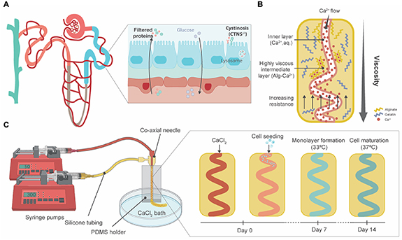
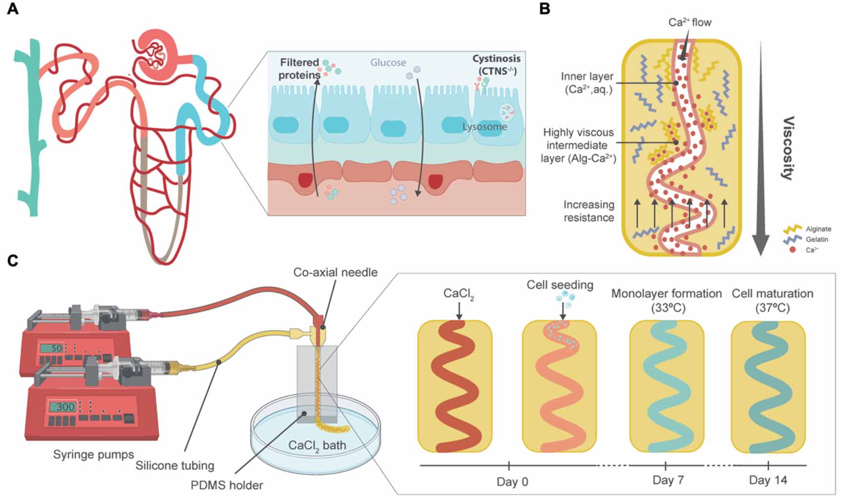
Figure 1. Graphical abstract. (A) The PT (blue) is the second segment of the nephron. In healthy circumstances, proteins are filtered from the bloodstream to the PT lumen (in blue) and amino acids and glucose are reabsorbed. Nephropathic cystinosis (CTNS-/- ) is a CKD condition in which a mutation of the CTNS gene leads to a loss of function of cystinosin, a lysosomal transporter. Hence, cystine accumulates in the lysosome, causing severe damage to the kidneys with a loss of amino acids and glucose in urine. (B) Ca2+ ions instantly crosslink with alginate, forming metal ion coordination bonds that increase the viscosity of the gel in the intermediate layer. The change of the viscosity combined with the increasing resistance from printing device walls allows the channel to coil. Adapted from [7]. (C) Schematics on the printing process and microfiber formation, seeding and maturation. After forming the inner channel via CaCl2 perfusion, PT epithelial cells were seeded. Upon culturing at 33 °C, the conditionally immortalized cells grew to form a monolayer. At 37 °C, these cells started to differentiate until full maturation within 7 days.
Download figure:
Standard image High-resolution imageKidney TE focuses on replicating the tissue microenvironment to understand and guide cell-cell and cell-extracellular matrix (ECM) interactions. Biocompatible hydrogels have received great attention because of their similarities to the ECM [11]. Moreover, their polymeric nature makes them easily tailorable to the mechanobiological properties of the ECM composition and compatible with three-dimensional (3D) (bio)printing techniques to create structures that resemble the PT [6, 12–14]. For PT-(bio)printing, the hydrogel biomaterials must meet specific criteria contingent on the printing modality. Extrusion (bio)printing in particular requires precursors that stabilize rapidly from a non-viscous stage [15]. Therefore, gelatin and alginate solutions prevail as favorable candidates since aqueous gelatin solutions respond rapidly to thermal variations and dissolved alginate to divalent ions such as Ca2+ [16]. Others have used the swift chemical crosslinking of alginate to create microfibers with coiled channels [7, 17]. Relying on a rapid viscosity change of the (bio)ink, a helicoidal lumen is formed within an extruded microfiber (figure 1(B)). Several 3D (bio)printing alternatives have been proposed, including sacrificial 3D printing to establish a perfusable PT and its adjacent capillary, a layer-by-layer construct focused on the interface between kidney epithelium and vascular endothelium and core–sheath microfluidic printing and self-organization for co-culture of epithelium and endothelium [6, 12–14]. Homan's thorough study proved enhanced tubular polarization markers (basolaterally expressed Na+/K+-ATPase and cilia at the apical membrane) and functionality (characterized by albumin uptake and megalin expression) as a result of a 3D convoluted microenvironment when compared to the 2D analogues [6]. Microfluidics-based core–shell extrusion has been proposed by Addario et al, to assemble PT constructs containing endothelial and epithelial cells [12]. Relying on PTEC migration, a straight hollow filament surrounded by endothelial cells was formed. Overall, the recent literature recognizes the urgent need for a 3D convoluted, and perfusable model of the PT and highlights its potential for pharmacological research. Yet, the architecture of the proposed models is not fully recapitulating the PT as relevant diameters and convolution seem to be elusive and mutually exclusive. Sacrificial printing allows for tubular diameters down to 150 µm according to the authors, yet quantitative results and assays were carried out for larger lumens (400 µm) [6]. Conventional microfluidic core–sheath extrusion achieves smaller channels (∼200 µm in diameter) but lacks convolution. The specific object of this study was to investigate the potential of one-step coaxial printing to achieve both convoluted architecture and a small diameter. Moreover, the beforementioned works were carried out with healthy epithelial cells. As of yet, phenotypically diseased cells have not been included. Thus, the suitability of (bio)printing for diseased PT models remains unassessed [6, 13].
Here, we hypothesized that a coaxial printing system can produce convoluted microfibers that mimic PT physiology, suitable for hosting healthy and cystinotic PTEC lines (figure 1(C)). We assessed the viability of the model during proliferation and differentiation of the cells. Cellular organization within the microfiber, monolayer integrity and polarization were evaluated by means of immunostaining. Finally, as a hallmark of PT function, transporter activity was studied for two important apical efflux pumps: breast cancer resistance protein (BCRP) and multidrug resistance protein 4 (MRP4).
2. Materials and methods
2.1. Cell culture
CiPTEC (MTA number A16-0147) were obtained from Cell4Pharma (Nijmegen, The Netherlands) and developed as described [18]. Briefly, PT cells obtained from urine from healthy volunteers (in compliance with the guidelines of the Radboud Institutional Review Board) were transfected with a temperature sensitive mutant U19tsA58 of SV40 large T antigen (SV40T) and the essential catalytic subunit of human telomerase. Two types of human ciPTEC were used in this study. The healthy control ciPTEC, also referred to in this paper as ciPTEC 14.4, and the cystinotic ciPTEC labeled as ciPTEC CTNS-/- . CiPTEC CTNS-/- is an isogenic cell line derived from ciPTEC 14.4 and generated using CRISPR-Cas9 [9], which harbors a biallelic mutation in exon 4 of the CTNS gene.
CiPTEC were cultured at 33 °C and 5% (v/v) CO2 up to 90% confluency to maintain a cell proliferation state. For maturation, ciPTEC were transferred to 37 °C for at least 5 days prior to experimental readout. CiPTEC were cultured in T175 culture flasks (Greiner Bio-One, Alphen aan den Rijn, The Netherlands), using Dulbecco's Modified Eagle Medium/Nutrient Mixture F-12 (DMEM/F-12) without phenol red (Gibco, Thermo Fisher Scientific, Paisley, UK), supplemented with 5 μg ml−1 of insulin, 5 μg ml−1 of transferrin, 5 μg ml−1 of selenium, 35 ng ml−1 of hydrocortisone, 10 ng ml−1 of epidermal growth factor, 40 pg ml−1 of tri-iodothyronine (Sigma-Aldrich, Saint Louis, MO, USA), 10% fetal bovine serum (FBS) (v/v, Greiner Bio-One, Alphen aan den Rijn, The Netherlands), and 1% penicillin/streptomycin (v/v, Gibco, Thermo Fisher Scientific, Paisley, UK).
2.2. Biomaterial ink
The formulation of the biomaterial ink was optimized to 1% alginic acid sodium salt from brown algae (w/v, Sigma-Aldrich, Saint Louis, MO, USA) and 8% gelatin (w/v, 300 g Bloom Type A, Sigma-Aldrich, Saint Louis, MO, USA) in MilliQ water. Crosslinking solution was prepared with 2% calcium chloride (CaCl2, w/v, Sigma-Aldrich, Saint Louis, MO, USA) in MilliQ water, which was filter sterilized. To visualize the formation of the hollow channels within the microfiber, the crosslinking solution was mixed with filter-sterilized food dye. Crosslinking of the microfibers was achieved by adding 2% microbial transglutaminase (w/v, mTG, MooGlue, Modernist Pantry, Eliot, ME, USA) to the cell culture medium for a minimum of 4 h. All components used were handled in a flow hood and filter sterilized to prevent contamination.
2.3. Wet weight measurements
Biomaterial ink blocks (n = 12) consisting of 1% (w/v) alginate and 8% (w/v) gelatin were assessed for long-term stability using a degradation assay. The biomaterial ink was crosslinked by a 2% (w/v) mTG solution for 4 h in 37 °C. Instant crosslinking of the alginate in the constructs was further obtained using 2% (w/v) CaCl2 solution. The samples (5 mm in length, 5 mm in width, and 1 mm in height) were cultured in DMEM/F-12 % + 0.02% (w/v) disodium pyrophosphate (Sigma-Aldrich, Saint Louis, MO, USA) at 37 °C and 5% (v/v) CO2 with medium refreshed every 2–3 days. Over a period of 4 weeks, the wet weights of the samples were measured at predefined time points and compared to the initial wet weights of the corresponding samples (t = 0).
2.4. Hydrogel permeability
Permeability of the used biomaterial ink was measured by the diffusion rate of inulin-fluorescein isothiocyanate (inulin-FITC, Sigma-Aldrich, Saint Louis, MO, USA) over a layer of the hydrogel using a Transwell® system (0.4 μm pore, Corning, NY, USA). The Transwell® inserts were washed with warm Hank's balanced salt solution (HBSS, Gibco, Thermo Fisher Scientific, Paisley, UK) buffer before being coated with pre-heated ink containing 1% (w/v) alginate and 8% (w/v) gelatin and deposited in different volumes to obtain a range of diameters (100, 200, 400 and 800 μm). The ink was crosslinked with 2% (w/v) CaCl2 for 1 h at room temperature whereafter it was removed and incubated with a 2% mTG (w/v) solution overnight at 37 °C. The basolateral compartment was exposed to 25 μg ml−1 of inulin-FITC in phosphate-buffered saline (PBS, Lonza, Basel, Switzerland) for 1 h at 37 °C and 5% (v/v) CO2. To measure the values of migrated inulin-FITC over the biomaterial ink layer, fluorescence of the apical compartment (100 μl per sample) was detected by a plate reader at excitation wavelength of 475 nm and emission wavelength of 530 nm. A calibration curve was included to relate the excitation and emission values to the associated concentration values. The measured values of migrated inulin-FITC over an empty Transwell® were used as the maximum value (100% leakage).
2.5. Printing device
The printing set-up consisted of (a) two syringe pumps, (b) a tailored printing device, (c) silicone tubing and (d) a CaCl2 bath. The printing device consisted of a polydimethylsiloxane (PDMS, SYLGARD™ 184 Silicone Elastomer, Dow, Midland, MI, USA) block that held a coaxial multi-layered nozzle while printing, allowing the extrusion of the hollow microfiber directly into the CaCl2 bath (12 mm Petri Dish Corning, NY, USA) (supplementary figure 1). The coaxial nozzle consisted of one 30 G needle that created the hollow channel and two 18 G needles, one to align the core and sheath and the second one to feed the biomaterial ink. The set-up was easy to use and clean, not easily clogged, reusable and autoclavable. Before use, the printing device, connectors, and tubing were autoclaved. The syringe pumps were cleaned with ethanol and air-dried in the flow hood.
2.6. Fabrication of and cell culture in microfibers
For the fabrication of microfibers, syringes were connected to pumps using 50 and 300 μl min−1 as settings for the core and sheath flows, respectively. The microfluidic device was connected to syringes containing the crosslinking solution (2% (w/v) CaCl2) and prewarmed ink (∼50 °C). Once the hollow microfiber was formed, ciPTEC were seeded immediately after at a concentration of 1 × 10⁷ cells ml−1 and a flow rate of 50 µl min−1 up until the entire construct contained cells. From a practical standpoint, when the transparent cell suspension is perfused, it replaces the dyed calcium chloride inside the lumen of the microfiber, which can be easily discern upon bare-eye inspection of the fiber. Next, the seeded tubes were sliced into <5 cm pieces and transferred to the wells of six-well plates by carefully handling them with tweezers. The samples were further crosslinked overnight at 33 °C and 5% (v/v) CO2 by adding 2% (w/v) mTG solution in the culture medium. The seeded tubes were incubated for 7 days at 33 °C and 5% (v/v) CO2 and then transferred to 37 °C and 5% (v/v) CO2 for, at least, five additional days.
2.7. Parameter influence on microfiber morphology
Flow rate and formulation of the ink are known factors that influence the morphology of the microchannel. To test the effects of experimental parameters on microfiber formation, the biomaterial ink composition was altered in the range of 0.5%–1.25% (w/v) for the alginate concentration and 4%–10% (w/v) for the gelatin concentration. These experiments were performed under a range of core flow (30–80 μl min−1) while the sheath flow was kept constant (300 μl min−1) to evaluate the influence of the core flow on the morphology of the microchannels in the microfibers.
The consistency of the results for this optimized protocol for microfiber fabrication was analyzed by measuring the inner and outer diameters of the produced microfibers (n = 3). The samples of each experiment were imaged at >15 different spots of the microfiber and 5 measurements per image were quantified using ImageJ (National Institutes of Health, Bethesda, MD, USA).
2.8. Diameter assay
To analyze the swelling and shrinking behavior of the microfibers over time, microfibers (1% (w/v) alginate and 8% (w/v) gelatin) were cultured over a period of 4 weeks in an incubator at 37 °C and 5% (v/v) CO2) in DMEM-F12 and 0.02% (w/v) disodium pyrophosphate, with medium refreshed every 2–3 days. Multiple images (⩾15) of the microfiber were taken at each time point and each image was measured at five places to ensure a representative measurement for each timepoint. Images were taken using a Nikon Eclipse Ti microscope (Nikon, Tokyo, Japan). The inner and outer diameters of the microfibers were measured over a period of 4 weeks, using ImageJ, and compared to the initial inner and outer diameters (t = 0).
2.9. Cell viability
To assess the viability of cells in the microfibers, calcein-acetoxymethyl-ester (calcein-AM, Invitrogen, Thermo Fisher Scientific, Carlsbad, CA, USA) and ethidium homodimer-1 (EthD-1, Invitrogen, Thermo Fisher Scientific, Carlsbad, CA, USA) staining was carried out on days 1, 3, 7 and 14 after printing. Cell culture media was removed from the samples and samples were rinsed twice with HBSS after which they were submerged in calcein-AM (2 μM in HBSS) and EthD-1 (4 μM in HBSS). Calcein-AM is hydrolyzed in living cells by esterase resulting in the fluorescent calcein that visualizes living cells. EthD-1 can visualize dead cells by staining the DNA as cell death causes cell membrane permeability allowing the dye to enter the cells. The samples were incubated at 37 °C, 5% (v/v) CO2 in the dark for 30 min followed by two quick rinses with HBSS. The visualization of the viable and dead cells was obtained using a confocal Leica TCS SP8 X microscope (Leica, Wetzlar, Germany) with fluorescent light at emission wavelengths of 490 nm and 535 nm for calcein-AM and EthD-1, respectively. Images were analyzed using ImageJ software Cell Counter plugin; cell viability is expressed as the percentage of number of live cells to total number of cells.
2.10. Immunocytochemistry
Microfibers with ciPTEC embedded were fixed for 30 min with 4% (v/v) paraformaldehyde (Pierce™, Thermo Fisher Scientific, Carlsbad, CA, USA) in PBS and permeabilized with 0.3% (v/v) triton X-100 (Sigma-Aldrich, Saint Louis, MO, USA) in PBS for 30 min at room temperature. Subsequently, the cells were exposed to the blocking buffer consisting of 2% (v/v) FBS, 0.5% (w/v) bovine serum albumin (Sigma-Aldrich, Saint Louis, MO, USA) and 0.1% (v/v) Tween-20 (Sigma-Aldrich, Saint Louis, MO, USA) in PBS for 60 min at RT. antibodies were diluted in the blocking buffer. Primary and secondary antibodies were incubated on a shaker overnight at 4 °C. A list of primary and secondary antibodies and their dilutions can be found in supplementary table 1. Immunofluorescence was examined using confocal microscopy and software Leica Application Suite X. Images were analyzed using ImageJ. Images were converted to eight-bit, Z-projections were made, and the same threshold was applied for every image. Actin filament directionality was quantified using the directionality functionality and Fourier components analyses.
2.11. Membrane transporter activity measurements
For functionality testing of various transporters (MRP4, BCRP), microfibers with ciPTEC encapsulated were cultured up to confluency at 33 °C 5% (v/v) CO2 and allowed to mature at 37 °C for 1 week. The samples were incubated for 15 min at 37 °C with 1 µM of non-fluorescent calcein-AM in HBSS, in which viable cells enzymatically converted calcein-AM to fluorescent calcein. To validate functionality of MRP4 and BCRP (excretion of calcein), incubation was done in presence or absence of MK571 (5 µM; Sigma-Aldrich, Saint Louis, MO, USA) and KO143 (5 µM, Sigma-Aldrich, Saint Louis, MO, USA) inhibitors of MRP4 and BCRP. The NucRed™ Live 647 ReadyProbes™ Reagent (Invitrogen, Thermo Fisher Scientific, Carlsbad, CA, USA) was added as a nuclear marker to be able to normalize for the number of cells. Samples that were incubated in presence of the inhibitors were pre-incubated with the inhibitors alone for 15 min. After incubation with calcein-AM (with or without inhibitors) the samples were washed with ice-cold HBSS, and images were taken using confocal microscopy. Images were analyzed using ImageJ. Images were converted to SUM Z-stacks and 'Area', 'Mean gray value' and 'Integrated density' were measured for microfiber regions of interest (ROI). Background fluorescence was corrected for microfiber ROI area and subtracted (protocol adapted from [19]). The resulting mean fluorescence intensity was then divided over the number of cells, counted manually with the ImageJ Cell Counter plugin.
2.12. Real time (RT)-qPCR of mRNA expressions
Gene expression analysis was performed by RT-qPCR (quantitative polymerase chain reaction) on ciPTEC after growing in the microfiber at 33 °C until confluency and 7 days at 37 °C. To obtain enough mRNA for a reliable gene expression measurement, up to 30 cm of cell layer confluent microfiber from the same printing batch was pooled. The samples were stored for at least 30 min at –80 °C and mechanically homogenized with vortex before mRNA was isolated using a RNeasy mini kit (Qiagen, Hilden, Germany) following the manufacturer's protocol. cDNA was prepared using 100 ng of sample RNA templates using the iScript1 cDNA Synthesis Kit (Bio-Rad Laboratories Inc., Hercules, CA, USA). For BCRP (ABCG2) and MRP4 (ABCC4) RT-qPCR was performed using Taqman Universal PCR Master Mix and Taqman Gene Expression assay (Applied Biosystems, Thermo Fisher Scientific, Carlsbad, CA, USA) for ABCG2 (Hs01053790_m1), ABCC4 (Hs00988721_m1) and reference gene RPS13 (Hs01011487_g1). Relative gene expression levels were calculated as fold changes using the 2−ΔΔCt method. All reactions were carried out with equivalent dilutions of each cDNA sample.
2.13. Perfusable chip system and inulin-FITC leakage assay
A custom-made chip was designed with Autodesk Fusion 360 software to connect the microfibers to a perfusion system after their maturation. The chip consisted of an open square with lateral channels in which 18 G syringe elbow needles are inserted (supplementary figure 2). The design was prepared for digital light processing 3D printing and printed with an EnvisionTEC Perfactory 3 Mini Multi Lens 3D printer (PIC 100 resin). The chips were post-processed via sonication (5 min, 2 times, 100% ethanol) and flashed (3000 times, EnvisionTEC, Dearborn, MI, USA). Microfibers were manipulated through the lateral chip channels and endings were inserted in the hollow lumen of the 18 G syringe needle. The syringe needles were pushed inside the chip lateral channels, forming a tight seal. A perfusable setup was created by connecting a syringe pump to tubing (PFA, 0.020" ID, IDEX Health & Science, Sigma-Aldrich, Saint Louis, MO, USA) via a luer lock, and connecting the tubing to the syringe needles via elastic tubing (1.6 mm of ID, Tygon, VWR, Amsterdam, The Netherlands). The water tightness of the system was tested assessing liquid leakage in the attaching points by perfusing food dyed MilliQ at 25 µl min−1 for 15 min.
To quantify the tightness of the cell monolayer, inulin-FITC solution (0.1 mg ml−1 in HBSS, Sigma-Aldrich, Saint Louis, MO, USA) was perfused through the microfiber lumen at 25 µl min−1 for 15 min using a syringe pump (Terumo, Tokyo, Japan). Empty and ciPTEC-containing microfibers were filmed with a fluorescence microscope with a green filter Nikon Ts2-FL microscope (Nikon, Tokyo, Japan). Images were taken at the moment of perfusion, after 5 min, and after 15 min perfusion. For quantification, images were also taken 10 s before and after previously mentioned timepoints. In ImageJ 'Integrated density' was measured for each whole image and a background intensity (>T0) was subtracted.
2.14. Statistical analyses
Unless specified otherwise, three microfibers per condition were used in three independent experiments. ImageJ (National Institutes of Health, Bethesda, MD, USA) was used for image analysis and quantification. Statistical analysis was performed in GraphPad PRISM 8 (GraphPad Software Inc., La Jolla, CA, USA), using unpaired t-tests and two-way ANOVA with Tukey's or Sídák's post-hoc test for multiple comparison analysis, where appropriate. Differences were considered significant with a p-value of p < 0.05. ∗ indicates p < 0.05, ∗∗p < 0.01, ∗∗∗p < 0.001 and ∗∗∗∗p < 0.0001. Results are shown as the mean ± standard error of the mean (SEM) of at least three replicates.
3. Results
3.1. The printing system reveals robust printing of perfusable coiled microfibers
A co-axial microfluidic device has been previously presented for the fabrication of microfibers with geometrically complex channels within a range of 20–300 μm [7]. The generation of the coiling microchannels during printing can be ascribed to the instant formation of calcium-alginate bonds that cause the hydrogel to acquire a higher viscosity while printing. By regulating the rates of these fluids (5 < Qsheath/Qcore < 10), the increase in viscosity around the core fluid will cause it to start spiraling (figure 1). The generation and characteristics of this helical channel within the microfiber can be managed by the control of the flow rate ratio of the fluids [7]. However, since unmodified alginate lacks cell-favorable bioactive elements and cells are unable to interact with the alginate matrix due to its hydrophilic nature, gelatin was included to improve cytocompatibility.
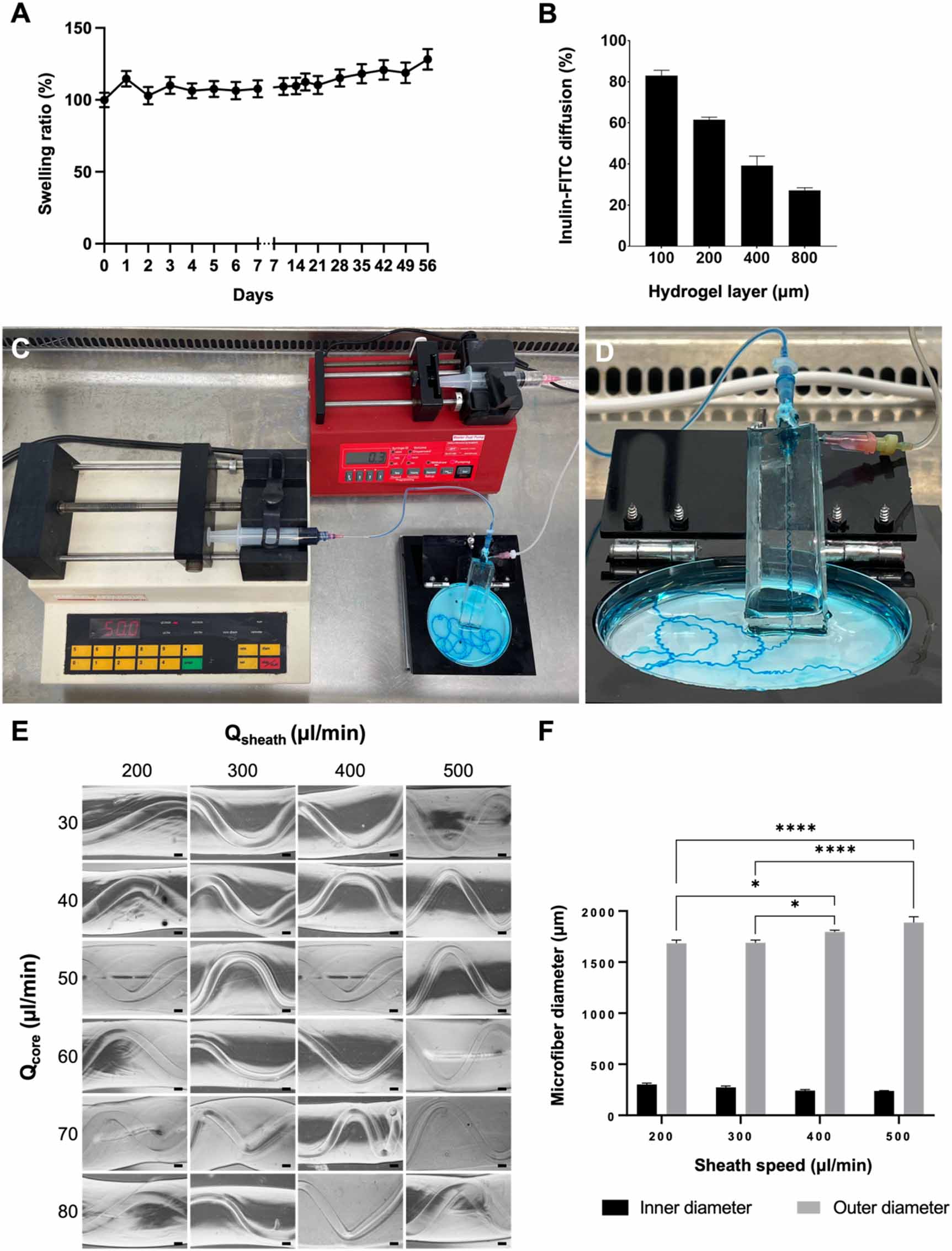
Biomaterial ink stabilization is proposed in two phases: a rapid ionic crosslinking process for alginate with Ca2+ and a prolonged enzymatic crosslinking of gelatin with mTG [20]. For the potential use of the microfibers in long-term culture, physical stability is of major importance. This stability was assessed in terms of changes in wet weight. Wet weight measured over the period of a month increased for the biomaterial ink blocks with 21% (±5%, p = 0.0001, unpaired t-test) in comparison to the initial weight at t = 0 (W0) in a gradual way (figure 2(A)). Additionally, the composition of the microfibers must allow the diffusion of nutrients, oxygen, and protein-bound toxins. To mimic reabsorption of solutes in the PT, a permeability assay was performed. Figure 2(B) shows an inversely proportional correlation between diffusion of inulin-FITC and thickness of the biomaterial ink in a time span of 60 min. The relative diffusion rates compared to the 100% control (empty Transwell®) were measured for hydrogel layers with a thickness of 100 μm (82.9 ± 2.65%), 200 μm (61.5 ± 1.3%), 400 μm (39.3 ± 4.5%) and 800 μm (27.1 ± 1.3%).

Figure 2. Biomaterial ink properties, printing system and printed microfibers. (A) Wet weight changes over a period of 42 days is presented as swelling ratio (%) compared to its initial wet weight (100%) on day 0. Overall minor gradual increase in weight was observed (data are presented as mean ± SEM of 12 experiments). (B) Quantification of diffusion of inulin-FITC over a hydrogel layer during 60 min compared to control (diffusion over empty Transwell® insert) showed an inversely proportional relation (mean ± SEM of two experiments). (C) Sterile printing setup inside the flow hood. Two syringe pumps extrude the sheath biomaterial ink (300 µl min−1) and the CaCl2 core (50 µl min−1 ). (D) Close up of the printing device consisting of the coaxial needles, silicon holder and petri dish. (E) Different sheath (Qsheath) and core (Qcore) rates were tested for the biomaterial ink formulation, but no trend was observed. (F) Quantification of inner and outer microfiber diameters showed a gradual increase of the outer diameter proportional to the sheath speed. No differences were found for the width of the inner channels (two-way ANOVA with Tukey's post-hoc test. Data are presented as mean ± SEM of 18 experiments). *p-value < 0.05, ****p-value < 0.0001. Scale bars: 200 µm.
Download figure:
Standard image High-resolution imageSimultaneously, the printing system was established. Figures 2(C) and (D) show the robust and sterilizable printing system for the fabrication of coiled and perfusable microfibers. All elements were compatible with decontamination strategies, either by air drying with ethanol 70% in the flow hood, UV light exposure for 20 min (syringe pumps, coaxial nozzles) or in a regular autoclave cycle (tubing, PDMS holder). Moreover, our system allows continuous printing, and was only limited by the size of the syringes containing the ink and the crosslinker solution.
Different core and sheath flows (Qcore, Qsheath), in combination with several alginate and gelatin proportions in the biomaterial ink were tested to assess their influence on the structure of the microfibers. A coiling nature was observed throughout the images and no trend was observed in the morphology of the microfibers due to the increase of gelatin or alginate concentration (supplementary figure 3). Accordingly, intermediate values of gelatin (8% w/v) and alginate (1% w/v) were chosen for the microfiber compositions. Additionally, the study of core and sheath flows showed no trend regarding the coiling of the inner microchannel (figure 2(E) and supplementary figure 4). However, there was a significant increase in the outer diameter of the microfibers corresponding to higher sheath feeding rates (figure 2(F)). The compromise between permeability and coiling set the core and sheath flows at 50 µl min−1 and 300 µl min−1, respectively, allowing the robust printing of perfusable microchannels with inner diameters of approximately 250 µm (figure 2(F)).
3.2. Engineered microfibers are stable over an extended test period of 42 days
Integrity of the bioengineered microfibers was examined at different time points: after printing (figure 3(A)), after seeding (figure 3(B)), and after culture for 14 days without and with ciPTEC (figures 3(C) and (D), respectively). The fibers remained firm, and were able to withstand manual handling from the printing setup to a common culture plate. Neither the seeding process nor the culture of cells for 14 days (including refreshing of the culture medium) affected the dimensions of the inner channels (figure 3(E)). Moreover, the bioengineered microfibers showed physical stability with an open lumen in long-term culture (42 days). Microfibers and the channels embedded within showed a minor reduction in diameter over a period of 1 month in the inner diameter (5% ± 1%, p < 0.0001), but not in the outer diameter (1% ± 1%, p = 0.4432), compared to the initial day (100%, t = 0) (figure 3(F)). Both inner and outer diameters showed no sudden changes during a period of 42 days.

Figure 3. Microfiber stability over time and biocompatibility with PT cells. (A)–(D) Bright-field microscopy showing the hollow channel immediately after printing (A), after seeding (B), cultured for 14 days without cells (C), and cultured for 14 days with ciPTEC forming a monolayer (D). Due to the coiling and because of gravity and vestigial flows after the printing, the cells tended to accumulate in the lower regions of the microfiber (B). However, as they proliferate, they eventually covered the lumen to form a tight monolayer. E) Microfiber inner diameter did not change by the presence of cells, whereas the outer diameter slightly decreased during the culture period (two-way ANOVA with Sídák's multiple comparison test. Data are presented as mean ± SEM of three microfibers after printing, six microfibers without cells, and eight microfibers with cells). The bioengineered PT microfibers were stable over an extended test period of 42 days, with a minor and fluctuating reduction of the inner diameter (unpaired t-test). Data are presented as mean ± SEM of three microfibers, each measured ⩽75 times) (F). ****p-value < 0.0001. Scale bars: 200 µm.
Download figure:
Standard image High-resolution image3.3. Convoluted CTNS-/- tubules are less viable upon prolonged culturing
The ciPTEC 14.4 line used for this work has shown to stably express the PT phenotype over a very high number of passages and when grown as kidney tubules on a fiber [10, 21, 22]. Further, the cystinotic cell line (ciPTEC CTNS-/- ) showed lysosomal cystine accumulation, increased autophagy and vesicle trafficking deterioration, the impairment of several metabolic pathways, and disruption of the epithelial monolayer tightness as compared to control kidney tubules [10]. These features are representative of the nephropathic phenotype. We here evaluated the cytocompatibility of the convoluted microfibers by performing live/dead staining for both cell lines (figure 4(A)). The results show that cell viability was high within the first week of culture, with significant differences between the cell types for days 1 (p = 0.0020), 3 (p = 0.0224), and 14 (p = 0.0284) (figure 4(B)). Upon prolonged culturing a decline in viability was observed, which was more pronounced in ciPTEC CTNS-/- .
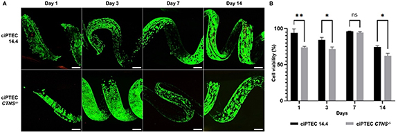
Figure 4. Microfiber biocompatibility with PT cells. (A) Live/Dead staining (calcein-AM/EthD-2) of ciPTEC 14.4 and ciPTEC CTNS-/- . (B) Cell viability (%) over time (number of days) obtained from A. (Two-way ANOVA with Sídák's multiple comparison test. Data are presented as mean ± SEM of 2 experiments for day 7, and 3 experiments for all other days). *p-value < 0.05, **p-value < 0.01. Scale bars: 200 µm.
Download figure:
Standard image High-resolution image3.4. Both ciPTEC 14.4 and CTNS-/- form organized and polarized monolayers in the microfibers
Next, the organization of the cell monolayer was evaluated by immunofluorescence staining and quantification of the intracellular F-actin filaments. Both ciPTEC lines were able to attach and grow for 14 days with phalloidin covering the lumens of the microfibers entirely (figures 5(A), (C) and supplementary figure 5). The cytoskeleton appeared aligned circumferentially to the channel for both cell lines, with comparable cell directionality for ciPTEC 14.4 and ciPTEC CTNS-/- (figures 5(B) and (D)). Furthermore, the cell polarization was assessed by the basolateral expressions of Na+/K+-ATPase and apical α-tubulin. Both ciPTEC lines exhibited positive immunostainings for the polarization markers, confirming the establishment of confluent epithelial monolayer and a response to basal-apical guidance (figures 5(E) and (F)).

Figure 5. Cell organization and polarization in the PT microfibers. (A) Microfibers were stained using phalloidin to show the organization of F-actin filaments in ciPTEC 14.4 (A) and CTNS-/- (C). Both models present an undisrupted cell monolayer covering the open lumen (see orthogonal sections). In blue: 4',6-diamidino-2-phenylindole (DAPI) (nuclei staining), in green: phalloidin (binds to actin filaments). (B), (D) Directionality analysis performed for at least four replicates. (E), (F) After maturation of 7 days the control (E) and cystinotic ciPTEC (F) form an organized 3D structure including primary cilia (α-tubulin staining). In blue: DAPI (nuclei staining), in red: Na+/K+-ATPase, in green: α-tubulin staining. Scale bars: 200 μm, unless indicated differently.
Download figure:
Standard image High-resolution image3.5. Healthy and cystinotic ciPTEC form tight monolayers in coaxially printed microfibers
Tight sealing of our engineered chip was confirmed by perfusing colored MilliQ water through a microfiber not containing cells (supplementary movie 1). It has been previously demonstrated that CTNS-/- cells grown on hollow fiber membranes form a less tight monolayer in comparison to a healthy control [10]. Here, we evaluated cell monolayer tightness by means of an inulin-FITC leakage assay. For this, microfibers with ciPTEC 14.4, ciPTEC CTNS-/- , and without cells were inserted in our custom designed chip and perfused with inulin-FITC at a rate of 25 µl min−1 for 15 min and visualized with an inverted microscope. In the empty (cell-free) microfiber, inulin-FITC diffused from the channel into the ink formulation from the start of perfusion (figure 6(A)), whereas in the microfibers with ciPTEC 14.4 the dye was retained in the channel (figures 6(B) and (D)), confirming a tight barrier formation. In the ciPTEC CTNS-/- channel the dye diffused significantly further into the ink than either the empty (p < 0.0001) or ciPTEC 14.4 (p < 0.0001) microfiber, confirming ciPTEC CTNS-/- are incapable of forming a leakage-tight barrier (figures 6(C) and (D)).

Figure 6. Renal barrier function in the microfiber chip tested by means of inulin-FITC. (A)–(C) Microfibers without cells (A), with ciPTEC 14.4 (B) and with ciPTEC CTNS-/- (C). Immunofluorescent images were captured after 0, 5 and 15 min of inulin-FITC perfusion. Dotted line in each image indicates the area measured for t = 0. (D) Fluorescence intensity at t = 5 and 15 min. A significant difference was found between the two timepoints for each condition, as well as between the different microfibers (two-way ANOVA with Sídák's post-hoc test. Data are presented as mean ± SEM of three measurements). ***p-value < 0.0005, ****p-value < 0.0001. Scale bars: 500 µm.
Download figure:
Standard image High-resolution image3.6. Engineered CTNS-/- tubules show reduced apical transport activities
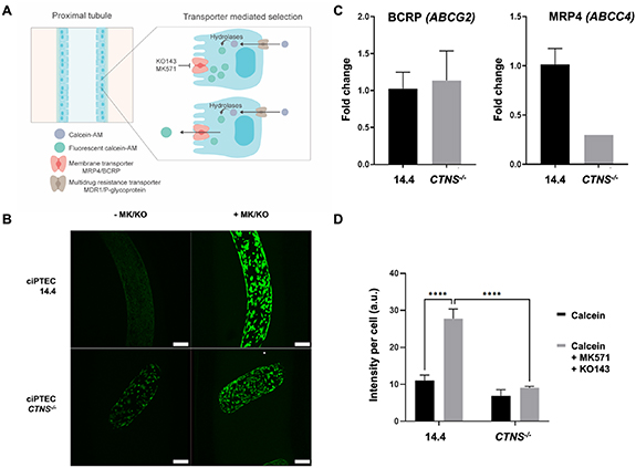
CTNS-/- is characterized by generalized dysfunction of the apical proximal tubular influx transporters (so-called renal Fanconi syndrome), developed during infancy, and gradually progressing towards end-stage kidney disease in the first decade of life in the majority of patients that are not treated with the cystine-depleting drug cysteamine [23, 24]. In the present study, we investigated whether the proximal tubular efflux transporters BCRP and MRP4 are affected in cystinosis. For this, we used calcein-AM that diffuses into live cells and is hydrolyzed into the fluorescent calcein, which can be actively secreted by the efflux pumps (figure 7(A)) [25]. Figure 7(B) shows representative images of the ciPTEC present in the channel of a microfiber exposed to calcein-AM with or without inhibitors for BCRP and MRP4 (MK571 and KO143). Upon addition of the inhibitors, an increase in intracellular fluorescence was observed (figure 7(B), right panels) demonstrative of the activities of both membrane transporters. Evaluation of the transporter gene expressions revealed no differences in ABCG2 between the two cell lines but a reduced expression of ABCC4 (figure 7(C)). Semi-quantification of the fluorescent images resulted in a 2.5-fold increase in signal after efflux pump inhibition in ciPTEC 14.4 whereas in ciPTEC CTNS-/- this increase was only 1.3-fold, suggesting reduced transporter activities in these cystinotic cells (figure 7(D)).
Figure 7. Engineered cystinotic tubules show reduced apical transport activities. (A) The non-fluorescent calcein-AM enters the ciPTEC cytoplasm via diffusion and is expelled via the Multidrug resistance transporter/P-glycoprotein. Upon inhibition of the apical membrane transporter MRP4/BCRP the accumulating calcein-AM is converted to the fluorescent calcein through intracellular hydrolases. The inhibitors MK571 and KO143 (MK/KO) prevented the intracellular fluorescent calcein from being transported extracellularly, which otherwise would be mediated by the membrane transporters BCRP and MRP4. (B) Representative images of PT exposed to calcein-AM with and without inhibitors to visualize the membrane transporter activities. (C) Relative ABCG2 and ABCC4 mRNA expressions of ciPTEC 14.4 and CTNS-/- cultured in microfibers. (D) Semi-quantification of the intracellular fluorescence intensities with MK571/KO143 inhibitors revealed in ciPTEC 14.4 a significant increase in intracellular fluorescent calcein compared to cells in the absence of inhibitors. This increase was not seen in ciPTEC CTNS-/- (two-way ANOVA with Tukey's post-hoc test. Data presented as mean ± SEM of at least n = 4 experiments). ****p-value < 0.0001. Scale bars: 200 μm.
Download figure:
Standard image High-resolution image
4. Discussion
The PT is a tube-like microfluidic structure in which curvature of the substrate plays a critical role in influencing PT cell polarization [26]. Accordingly, developing PT models should revolve around mimicking the same working principle. Previous reports support 3D (bio)printing as a suitable technique for generating tube-like structures, often accompanied by endothelial cells that account for a rudimentary microvasculature [6, 27]. Yet, these proposed models mainly resembled the straight region of the PT, simpler to fabricate with the currently available biofabrication methods. We hypothesized that co-axial printing is a suitable technique for generating microfibers to model the convoluted PT microenvironment, combining biomaterials and cells into a 3D design representing architectural complexity of the native tissue. Accordingly, we developed an innovative printing system for helical microfiber fabrication which closely mimics the convoluted PT microenvironment and allows for cell proliferation and maturation. By using a biomaterial ink consisting of alginate and gelatin, crosslinked by CaCl2 and mTG, the microfibers are stable over a long period of time. We demonstrated that they can be used to study healthy and diseased PT by looking at cell viability and transepithelial transport, as both ciPTEC 14.4 and CNTS-/- formed tight and polarized monolayers in the microfibers.
Previous approaches for helical coaxial printing used a glass capillary to create the microfibers or manual insertion of a needle within the channel to perfuse the channels with a cell suspension [7, 17]. However, these methods appeared laborious, material consuming and limited the microfiber to contain one microchannel only and one cell type. This approach was not a suitable seeding option for our system as the diameter of the microchannel within the microfibers was too small and convoluted in shape to manually insert the needle without perforating the fiber. Others have proposed the use of syringes and glass capillaries to attach fibers to a perfusion system with vacuum, but the limitations were similar: labor-intensive and not straight-forward [28]. Here, the glass was substituted by a PDMS holder and a coaxial needle, allowing the automatization of the system using syringe pumps both for the channel formation and cell seeding. We achieved a one-step method for microfiber fabrication and cell seeding, by perfusing the cell suspension through the channels directly after the fabrication of the fiber. PDMS is a widely used polymer in the field of microfluidics, due to its favorable mechanical properties, cytocompatibility, moldability, gas permeability, and optical clarity. Nevertheless, PDMS has limited capacities for high-throughput manufacturing and is known for resorption of small hydrophobic molecules [29]. However, the advantages of this PDMS microfluidic printing device further include its fast production time, the ability to reuse and autoclave the material, and ease to handle compared to glass capillaries. Using this device, we obtained robust fabrication of microfibers with specific parameters optimized for PT engineering.
Besides a robust and sterilizable manufacturing system, the formulation of a cytocompatible and stable biomaterial ink is key for the fabrication of the coiled microfibers. Alginate has been proposed earlier for microfiber fabrication, due to its rapid physical crosslinking when exposed to Ca2+ [7, 17]. Nevertheless, alginate in its unmodified form fails to support cell adhesion and cell proliferation [30]. Hence, it is often combined with gelatin, a derivative from collagen which is a main component of connective tissues [6, 13, 31–37]. Gelatin supports cell adhesion as it retains many functional groups identified by cells and it can be stabilized in the long-term via enzyme-induced chemical crosslinking. We showed that the biomaterial ink remained stable over 42 days, enabling long-term cultures. Moreover, we characterized and defined the diffusion limit of the hydrogel via inulin-FITC measurements. As expected, thickness restricted diffusion. When studying the microfiber diameter, our results indicated a gradual increase of the outer fiber diameter directly proportional to higher sheath rates. Thick hydrogels might jeopardize the passive diffusion of nutrients towards the inner channels, while permeability for nutrients, oxygen and solutes are critical for cell viability and modeling PT. In previous reports on perfusable coiled microfibers, the properties of the helix (amplitude, helix pitch) were tunable and responded to flow rates [7, 17]. However, we did not observe a major difference in the coils' features for either feeding rates or ink compositions with regards to relative percentages of alginate and gelatin. While the reason remains unclear, the previously reported coiled microfibers used only alginate, whereas we introduced a second polymer to improve cytocompatibility. Changes in the rheological properties when mixing gelatin and alginate have been identified and might be responsible for the observed phenomenon [38].
The incorporation of cells in a precise manner is essential to generating a monolayer in the channels and this was achieved in a one-step process, where the cells could be incorporated in the system immediately after the channel formation. Cells from both healthy and cystinotic ciPTEC lines were able to adhere and proliferate in the helical microchannels, with high viability over the first week of culture but a slight decrease over time that was more pronounced for the CTNS-/- model. An explanation for this decrease in viability is that the natural turnover of dead cells (EtHd-1, red fluorescence) that detached from the microfiber accumulated in the lumen, because there was no active perfusion of the microfiber during the culture period. Another explanation might be a lack of oxygen supply that is quite common in thick hydrogels and leads to cell necrosis, which could be prevented by having a perfusable or a vascularized set-up [39].
The correct function of a bioengineered PT relies on the establishment of a tight and cohesive barrier-forming monolayer responsible for vectorial transport [40]. The F-actin staining of the microfibers showed a homogeneous monolayer for both healthy and CTNS-/- ciPTEC, advocating for coiled microfibers as a 3D model of the PT. A recent study using the same cell lines in a 3D microenvironment showed monolayer dysregulation with differences in the cell orientation in the CTNS-/- knockout model compared to healthy cells [10]. Inconsistencies between this and a previous study can be attributed to the 3D models applied, that is, microPES type TF10 hollow fiber capillary membrane versus hybrid hydrogel material in this study, but also the distribution of the cells within the structures, i.e. convex versus concave surfaces, with ciPTEC exhibiting a preference for concave over convex surfaces [26, 41, 42].
In the coaxially printed constructs, both cell lines were able to mature and polarize with a basolateral localization of Na+/K+-ATPase and α-tubulin at the apical side of the cells, which is crucial for performing key PT functions like transepithelial transport. In cystinosis, a generalized dysfunction of the PT is observed, which is characterized by the presence of, among others, polyuria, phosphaturia, glycosuria and proteinuria, also termed as renal Fanconi syndrome [23, 24]. Our inulin-FITC leakage confirmed this by showing significantly higher leakage in the CNTS-/- group compared to the healthy cells in the microfiber, which shows a dysfunction of the monolayer tightness. Remarkably, inulin-FITC leakage in the CTNS-/– seeded microfibers was higher than empty microfibers. A possible explanation could be that due to the accumulation of intra-lysosomal cystine, lysosomal acidification occurs. Indeed, renal acidosis is the most common symptom in CTNS-/- patients [43], which impacts directly the pH environment. Local pH alterations can induce destabilization and degradation of the microfiber gel, leading to an increased inulin-FITC leakage.
The cystine-induced injury of proximal tubular cells leads to altered ATP metabolism, altered glutathione metabolism, and apoptotic cell death and affects apically expressed transporters. However, it was previously shown that P-glycoprotein (ABCB1), an ATP-dependent efflux pump, may not be affected in cystinosis, despite a renal Fanconi-like phenotype in knockout mice [44, 45]. We evaluated two other apically expressed ATP-dependent efflux pumps, namely BCRP (ABCG2) and MRP4 (ABCC4), and demonstrated their functional presence in the engineered healthy PT microfibers, and impaired function in the CTNS-/- PT model. The reduced transport activity can likely be attributed to diminished MRP4 function as its gene expression was found to be 3-fold downregulated whereas ABCG2 expression was not affected in the CTNS-/- knockout model. Dysregulation of MRP4 in CTNS-/- has not been reported earlier, although a decreased transporter expression was found in other diseases, including endotoxemia and prostate cancer, and polymorphisms in ABCC4 may lead to hyperuricemia [46–49].
In this paper, we demonstrate how coiled microfiber channels favorably model the healthy and cystinotic PT. The next step would be to create a vascularized PT model by introducing endothelial cells to the system. Early attempts of vascularized PT models open a new venue to further study healthy and diseased PT function, crosstalk between epithelial and endothelial cells and solute transport across lumens [13]. Pilot experiments using our printing set-up show the feasibility of creating two channels within a single microfiber, allowing for both epithelial and endothelial cell compartments (supplementary figure 6). Because of the high cell-affinity of the hydrogel precursor, supporting tubular cells such as fibroblasts or immune cells can potentially be included in the present model by, for instance, direct seeding on top of the microfiber. Future studies are aimed to propose a more compete PT model, which entails advancing the printing, seeding and perfusion techniques, and ensuring different cell-lines seeded in separate channels. Fluid shear stress is known to be important for enhancement of cell functionality and cell morphology, which in the future could be studied in a perfusable set-up as proposed in supplementary movie 1 [6, 50–52]. Additionally, recent progress in differentiation methods for PTEC and endothelial cells from induced pluripotent stem cells enable the creation of personalized models [53–55].
5. Conclusions
Our coaxial printing system allows the robust and straightforward fabrication of coiled perfusable microfibers, which replicate the kidney proximal convoluted tubules. The microfibers offer a complex microenvironment in which the cells exhibit mature markers, such as functional transporters and polarized monolayers. Moreover, this model has proven to support healthy and cystinotic PT cell lines and allows for mechanistically studying tubulopathies. Furthermore, with the future aim to incorporate two separate channels with different cell types, a more sophisticated method that enables independent perfusion is needed. By including patient-derived cells of various diseases, this model could offer a broad platform for personalized medicine in the PT. Finally, with the possibility to perfuse the microfibers, we are paving the way for assessment of metabolite transport and drug testing, making this model one step closer to a structurally relevant PT model.
Acknowledgment
The authors would like to gratefully thank Koen Westphal for the training provided for the confocal microscopy.
Data availability statement
The data that support the findings of this study are available upon reasonable request from the authors.
Funding
This work was supported by funding from The Dutch Kidney Foundation (17PHD16, A M G and 18KVP01, A M G, C S, Y S Z), the Hofvijverkring Visiting Scientist Program (Y S Z, A M G, C S), the Materials Driven Regeneration Young Talent Grant (A M G, C S), H2020 WIDESPREAD-05-2018-TWINNING Remodel (S M M; R M), the IMAGEN project which is co-funded by the PPP Allowance made available by Health∼Holland, Top Sector Life Sciencezs & Health, to stimulate public–private partnerships (IMplementation of Advancements in GENetic Kidney Disease, LSHM20009; E S G, R M), Utrecht Institute for Pharmaceutical Sciences (M G V) and Brigham Research Institute (Y S Z).
Ethical statement
The study was approved by an institutional (Radboudumc) ethics board. Informed consent wasobtained from all human donors and the collection of these samples was approved by the committeeon research involving human subjects (Commissie Mensgebonden Onderzoek) of the Radboudumc. Research was conducted in accordance with the principles embodied in the Declaration of Helsinki andin accordance with local statutory requirements.
Supplementary data (0.5 MB PDF)
Supplementary data (4.1 MB MP4)