
Abstract
Neuroblastoma is an extracranial solid tumor which develops in early childhood and still has a poor prognosis. One strategy to increase cure rates is the identification of patient-specific drug responses in tissue models that mimic the interaction between patient cancer cells and tumor environment. We therefore developed a perfused and micro-vascularized tumor-environment model that is directly bioprinted into custom-manufactured fluidic chips. A gelatin-methacrylate/fibrin-based matrix containing multiple cell types mimics the tumor-microenvironment that promotes spontaneous micro-vessel formation by embedded endothelial cells. We demonstrate that both, adipocyte- and iPSC-derived mesenchymal stem cells can guide this process. Bioprinted channels are coated with endothelial cells post printing to form a dense vessel—tissue barrier. The tissue model thereby mimics structure and function of human soft tissue with endothelial cell-coated larger vessels for perfusion and micro-vessel networks within the hydrogel-matrix. Patient-derived neuroblastoma spheroids are added to the matrix during the printing process and grown for more than two weeks. We demonstrate that micro-vessels are attracted by and grow into tumor spheroids and that neuroblastoma cells invade the tumor-environment as soon as the spheroids disrupt. In summary, we describe the first bioprinted, micro-vascularized neuroblastoma—tumor-environment model directly printed into fluidic chips and a novel medium-throughput biofabrication platform suitable for studying tumor angiogenesis and metastasis in precision medicine approaches in future.
Export citation and abstract BibTeX RIS

Original content from this work may be used under the terms of the Creative Commons Attribution 4.0 license. Any further distribution of this work must maintain attribution to the author(s) and the title of the work, journal citation and DOI.
1. Introduction
Modeling the tumor-environment holds tremendous potential to better understand the mechanisms how solid tumors communicate with neighboring, non-transformed cells and how they manipulate surrounding tissue to optimize growth conditions, vascularization and nutrient/oxygen transport. The tumor-environment plays a crucial role in cancer development and in the resistance to therapeutic drugs or immune therapy. Due to individual gene expression patterns and mutations, the mode of interaction between tumor cells and tissue environment differs between tumor types and patients. Cancer-specific in vitro models that mimic the tumor environment can be personalized with patient-derived cells to rebuild the individual tumor—micro-environment in vitro. Such personalized tumor-tissue models may serve as drug-testing platforms to identify and optimize individual therapy regimens or provide novel insights into the signaling between specific cancer types and their microenvironment. This is also true for childhood malignancies such as neuroblastoma tumors that derive from primitive neuronal cells of the autonomous nerve system and usually develop in early childhood. Depending on age and genetic abnormalities, children with high-stage neuroblastoma tumors still face a rather poor prognosis with up to 40% lethality despite chemo- and radio-therapy [1]. Therefore, there is a significant need to develop patient-tailored therapies by identifying those drugs that provide optimal benefit at minimal side effects. Precision medicine approaches based on patient-derived cancer cells and complex soft tissue equivalents will significantly improve the chances of these young patients.
A major challenge in developing an appropriated tumor-microenvironment is to trigger vessel formation and tumor-vascularization. Significant progress has been achieved in generating functional, perfusable vasculature in soft 3D hydrogels by combining endothelial cells with mesenchymal stem cells (MSCs) which are critical for perivascular support and stabilization of newly formed vessels [2–6].
The tumor microenvironment can be optimized by choosing suitable hydrogel components and cell types that are present also in native tissue within a structured 3D bioprinted tissue model (reviewed in [7, 8]). Natural polymers such as collagen and fibrin were applied for 3D hydrogels due to their high resemblance of physiological extracellular matrix (ECM) composition, favorable adhesion motives for cell attachment and angiogenesis promoting features [2, 3, 9, 10]. The major drawback of those natural materials is their poor mechanical stability und durability during long-term cultivation [11, 12]. Functionalized gelatin-methacrylate (GelMA), as a semi-natural polymer, provides advantageous hydrogel properties including tunable mechanical stability, intact adhesion motives, protease degradation sites and fast cross-linking features [3, 9, 13].
In contrast to classical 2D cultures and static tube formation assays on Matrigel®, microfluidic models implement physiological flow shear stress levels and interstitial flow, which significantly affects angiogenesis and vascularization in normal and malignant tissue [14–17]. Standard procedures for microfluidic chips manufacturing include soft photolithography procedures with synthetic polymer materials like polydimethylsiloxane [18] or polystyrene [19]. This generates chips with standardized and pre-defined channel geometries that are loaded with cells or cell-laden hydrogels [16]. However, models with such simplified channels lack the complexity of physiological, branched and interconnected micro-vessel networks and capillary geometries, which are spontaneously formed by cells in natural hydrogels [20]. Additionally, the size of microfluidic chips limits the potential for tumor model systems as nutrient and oxygen limitations in the core of solid tumors can only be addressed in tissue surrogates in millimeters thickness. 3D bioprinting, on the other hand, allows the assembly of, multilayered, structured and several millimeters thick hydrogels that much better resemble natural human tissue than most microfluidic devices. Via extrusion-based bioprinting, hollow structures are generated with sacrificial substances (e.g. Pluronic F127) and micro-jetting is used for cell-friendly, contact-free printing of low-viscosity cell-laden hydrogels [4, 21]. The main obstacle of current 3D-bioprinted models is a standardized and easy-to-use platform technology for parallelized long-term culture at physiologic flow conditions in a perfusion system.
In this work, we combined 3D bioprinting and fluidic chip technology to generate a complex vascularized tumor-on-a-chip model for mid-throughput applications. The developed platform combines the standardized production and easy handling of fluidic chips with the complexity of a millimeter-thick, human, vascularized soft tissue equivalent. Vessel networks spontaneously formed in the matrix were combined with endothelial cell coated conduits to design a vascularized tumor-microenvironment for studying tumor angiogenesis and metastasis. Mesenchymal-like stem cells differentiated from induced pluripotent stem (iPS) cells promoted vessel formation thus opening new avenues for patient-derived, vascularized tissue models and precision medicine applications in future.
2. Results
2.1. 3D bioprinted tumor microenvironment in laser-manufactured fluidic chips
As chip-material for our '3D bioprinting-on-a-chip platform' we use polymethylmethacrylate (PMMA). PMMA sheets are laser-engraved to achieve channel structures and specific surface patterning on macroscopic and microscopic level using an industry-standard laser engraving system (Epilog Laser, Cameo, Munich). PMMA chips are bonded to glass slides using a biocompatible adhesive tape (ARcare 90106NB, Adhesive Research Inc., Pennsylvania, USA). High-throughput laser engraving allows straightforward production of standardized PMMA slides that serve as hard shells for bioprinted tissue equivalents (figure 1). Cell-laden hydrogel is then printed into the chamber(s) of the chip with contactless micro-jet printing in a 3D Discovery BioSafety bioprinter (RegenHu, Villaz-Saint-Pierre, Switzerland). Tissues in 12 chips are fabricated in one run with approximately 3 min printing time per chip (supplemental movie M1). For the generation of hollow channels within the soft tissue, the fugitive thermo-sensitive support material Pluronic F-127 was extrusion printed in a way that channel structures through the tissue are directly connected to the laser-engraved channels on the chip. Pluronic F-127 liquefies when lowering the temperature below 15 °C. After full polymerization and shifting to lower temperatures, the liquefied support material is evacuated leaving hollow channels (figures 1(c) and (d)).
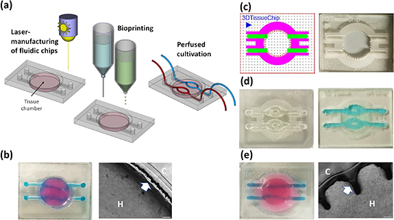
Figure 1. Bioprinting of soft-tissues into laser-engraved fluidic chips. Fluidic chips of diverse designs are produced by laser-engraving and cutting of acryl sheets with an adhesive tape on the bottom side. Acryl sheets are bonded to glass slides and serve as platforms for the assembly of 3D bioprinted tissue. Into the central chamber, tissue is printed layer-by-layer using microjetting, fugitive support material for channel structures is added by micro-dispensing. Printed tissues are grown and differentiated either at static or perfused cultivation conditions (a). In primary designs, tissue contracts during maturation, leading to detachment from walls (arrow) and disruption of perfusion channels (b). Chips are designed in CorelDraw Graphics Suite software with colors representing different cutting and engraving modes. Red lines are cut, green, blue and magenta areas are engraved at different settings with an epilog laser engraving system (c). 3D bioprinted tissue chip before the removal of the sacrificial structure material Pluronic F-127 ((d), left) and after perfusion of hollow channels with blue-colored PBS ((d), right). Modified wall and surface structure improve tissue—acryl adhesion, prevent interruption of perfusion channels and detachment from walls ((e), H = hydrogel, C = chip).
Download figure:
Standard image High-resolution imageFirst generations of chips contained channels on the PMMA bottom side, connectors on both sides of the chip and a central round cavity for the bioprinted tissue (figure 1(b)). These chips required more handling as the inlets to the 'tissue chamber' needed to be manually closed with drops of Pluronic F-127 before printing to prevent biomatrix blocking them during the printing process. However, with these chips we observed two difficulties: In some cases, medium diffused between hydrogel and glass, which detached the bioprinted tissue from the glass bottom. More importantly, upon longer culture (>2 weeks) the tissue frequently detached also from the walls of the chamber, which interrupted perfusion through channels and caused leakage (figure 1(b), right). This results from cell-mediated contraction forces in the developing tissue, which causes shrinkage of the tissue equivalent. We therefore developed a chip design, where PMMA chips are engraved from top at varying parameters (as visualized by different coloring in the print file (figure 1(c), left)) to achieve different depths and surface modifications. As chips do not need to be turned upside-down during engraving, this streamlines the manufacturing procedure and increases the precision of the engraving/cutting process. Inlets and supply channels are engraved at high laser intensity to achieve deep cavities in the PMMA and the camber-wall is cut with a ridged surface (one design example shown in figure 1(b)) to efficiently anchor the tissue to the PMMA chip. Surface areas of the chip were engraved around the central chamber and along the supply channels. For this patterning, the ratio between laser-pulse frequency and engraving speed was adjusted in a way that the laser generated a rough, burling-like surface for improved hydrogel anchoring to the PMMA.
To manufacture multi-layered tissue in these chips, a thin layer of bioink is printed first into the central chamber using microjet heads followed by UV-crosslinking. After polymerization, channel geometries are drawn with 35% Pluronic F-127 using a direct-dispensing print head and the areas in between and above the Pluronic-strands are then printed layer-by-layer via microjetting. Like in the central tissue chamber, Pluronic F127 strands in the supply channels are surrounded with bioink, thus building a tissue equivalent with living afferent and efferent supply vessels that are efficiently anchored to the PMMA. This also distributes forces that occur during tissue maturation and further prevents disruption of channels. After printing, the chips are exposed to violet light (5 mW cm−2) for 2 min to fully polymerize the bioinks. This improved chip design efficiently prevented detachment from walls and channel leakage after longer cultivation (figure 1(e)).
2.2. Optimization of 3D endothelial cell coating of perfusion channels
Hollow channels through a fibroblasts-containing tissue equivalent were filled and incubated with an acidic collagen type I solution (0.3 mg ml−1, Arthro Kinetics Biotechnology, Krems, Austria) for 1 h to coat the inner walls of the conduits with a thin layer of collagen. This pre-coating improves the cell adhesion of endothelial cells to the inner conduit wall (supplemental figure S1 available online at stacks.iop.org/BF/14/035002/mmedia). To generate an endothelial cell layer we used human umbilical vein cells (HUVEC) which were immortalized and fluorescent-labeled by infection with hTert- and EYFP-encoding retroviruses. Coating the conduit walls with endothelial cells by flipping the chips every 15 min upside-down resulted in an inhomogeneous cell distribution on the channel walls. Less endothelial cells adhered to the roof- and side-walls of the channels, as shown in confocal images in figure 2(b). We therefore developed a programmable, 3D-orbital shaker to improve and standardize the conduit wall-coating with collagen and endothelial cells (figure 2(a)). The tissue chips are fixed in a laser-manufactured acryl-platform magnetically anchored to the orbital shaker plate and are rotated along the x-axis with defined stops every 90° and slowly agitated along the y-axis. This allows the cells to adhere also to the side- and roof-walls and results in a uniform endothelial cell coating of perfusion channels (figure 2(b) and supplemental movie M2).

Figure 2. Endothelial cell coating of conduits to mimic blood-tissue barrier function. For optimized coating of inner channel linings we developed a programmable 3D orbital shaker that halts rotation at distinct positions for defined times to achieve optimized endothelial cell adhesion (a). Compared to manual flipping of the fluidic chips ((b), top panels), the inner surfaces of shaker-incubated tissues are homogenously coated with green fluorescent endothelial cells (HUVEC/hTERT-EYFP) as imaged by confocal microscopy ((b), bottom panels, scale bar 50 µm). Tissue chips with fibroblasts (HFF/hTERT-ECFP) in the hydrogel matrix and hollow channels with or without endothelial cells (HUVEC/hTERT-EYFP) were perfused with red fluorescent 70 kDa dextran rhodamine B conjugate (0.25 mg ml−1) to assess diffusion into the hydrogel matrix within 30 min (c). Left panels: fibroblast containing hydrogels with uncoated channels. Right panels: endothelial cell coating using orbital shaker procedure. Size marker 200 µm. Red fluorescence in the matrix after 30 min corresponds to the diffusion distance of dextran beads and thus to the endothelial barrier function. Graph shows comparison in red fluorescence between non-coated channels and channels covered with endothelial cells (d). Shown is the mean of three independent experiments. Statistical significance was assessed with student's t-test (**p < 0.01).
Download figure:
Standard image High-resolution imageTo test how the confluent endothelial cell layer affects vessel permeability, we injected a dextran-rhodamine B conjugate into the vessels and imaged the diffusion rate of the red-fluorescent dextran into the surrounding hydrogel by time laps fluorescence microscopy. In control chips without endothelial cells dextran markedly diffused into the hydrogel matrix within 30 min of incubation, whereas in channels coated with endothelial cells, the diffusion into the matrix was significantly reduced. In these channels, the margin of red fluorescent staining mostly lines up with the green fluorescent endothelial cell layer. The results demonstrate that the endothelial cells on the inner walls of the perfusion channels fulfill a barrier function similar to the endothelium in living organisms (figures 2(b) and (c)). Of note, endothelial cells only form an intact barrier, if the matrix of the tissue equivalent contains either fibroblasts or MSCs.
2.3. Spontaneous formation of micro-vessel networks
The diameter of the printing needle used for extruding the sacrificial support material is the limiting parameter for channel size and network complexity. When using a 27 G-needle the minimal diameter of the printed channels is approximately 200 µm. Dense, 3D microvascular structures below this resolution can be achieved either by photolithography or via triggering spontaneous self-organization of endothelial cells. Thereby, an interconnected micro-vessel network with an open lumen is formed which provides the tissue with nutrients and oxygen supply. Various hydrogel compositions were tested to increase endothelial cell viability and formation of micro-vessel networks. A base hydrogel of 5% GelMA was mixed with the additives alginate (5%), functionalized alginate-YISGR (5%), chitosan (1.25 mg ml−1 ), hyaluronic acid (2.5 mg ml−1 ), fibrinogen (2.5 mg ml−1) or fibronectin (0.25 mg ml−1) and was 3D bioprinted with 106 HUVEC/hTert-EYFP cells/ml (data not shown). The viability and vessel formation potential of endothelial cells within 3D bioprinted tissue constructs depends on the co-cultivation with fibroblasts or MSCs: HUVEC/hTert-EYFP cells 3D bioprinted in 5% GelMA and 2.5 mg ml−1 fibrinogen in a monoculture underwent cell death within 4 d (figure 3(a)). In contrast endothelial cells in a co-culture with primary adipose-tissue derived stem cells (ADSCs) in a ratio of 1:0.75 were viable 4 d after printing and began to form vessel networks at day 7 which matured into larger vessels on day 11 (figure 3(b)). Vessels formed by endothelial cells are stabilized by other cell types, most importantly by pericytes and smooth muscle cells. These additional cell types can either be directly supplemented [22] or differentiate at optimal conditions in situ from MSCs [23]. It is under debate, whether a subpopulation of MSCs represent pericyte-like cells [24]. The hydrogel composition of 5% GelMA and 2.5 mg ml−1 fibrinogen provided an ideal microenvironment to allow cell migration, differentiation and vascular remodeling. After 14 d of culture, the tissue on-a-chip model was still stable with intact, permeable channels. To assess maturity of the vessel networks we stained HUVEC cells cultured in 2D (figure 3(c)) or grown in bioprinted tissue sections for 12 d (figure 3(d)) with antibodies directed against human CD31 and human VE-cadherin. We observed specific staining at cell-to-cell contacts in 2D cultures and in 3D tissue equivalents suggesting that microvessels undergo maturation in bioprinted tissue. To assess the biocompatibility of the bioink formulation also for other types of endothelial cells we tested human dermal microvascular endothelial cells (HDMECs). As shown by confocal imaging and 3D reconstruction, also this type of endothelial cells forms 3D microvessel structures with apparent open lumen (supplemental figure S2).

Figure 3. Micro-vessel formation in bioprinted soft tissue on-a-chip. Endothelial cells (HUVEC/hTert-EYFP) were printed in monoculture (a) or in co-culture with adipose-tissue derived stem cells (ADSCs) (b) in a GelMA (5%)—fibrinogen (2.5 mg ml−1) hydrogel directly into the tissue chamber of the PMMA-glass chips and cultured for the times indicated. The expression of endothelial cell markers CD31 and VE-cadherin was analyzed in HUVEC cells cultured in eight-well μ-slides (Ibidi) with glass-bottom to confluence and fixed with ROTI®Histofix (c). Images were acquired using a Zeiss Apotome 0.2 system (scale bar 5 µm). Bioprinted tissue equivalents were cultured for 12 d, fixed, embedded in paraffin and sliced. EYFP-autofluorescence was blocked with Sudan Black B and sections were stained with anti-CD31 and anti-VE-cadherin. Nuclei were stained with Hoechst33342 (scale bar 20 µm). Cross-sections of vascularized tissue models fixed with 2.5% glutaraldehyde were imaged with a scanning electron microscope (SEM) after 14 d of cultivation (c), 27× and 150× magnification). Open pores within a channel structure are marked with white arrows (d), 150× and 450× magnification).
Download figure:
Standard image High-resolution imageCross sections of the vascularized tissue equivalent were imaged by scanning electron microscopy (SEM) to analyze channel architecture and the ultrastructure of the matrix (figure 3(e)). Open pores were observed within the channels which indicate an open lumen formation of the microvessel structures in the 3D bioprinted tissue channels (figure 3(f)). The matrix of vascularized tissue models after cultivation for 21 d was intensively remodeled in comparison to cell-free hydrogel constructs, which presented with smooth and uniform cross-sections (supplemental figure S3).
2.4. Effects of pro- and anti-angiogenic treatment on microvessel network in bioprinted tissue
Next, we investigated how the microvessel network responds to pro- and anti-angiogenic factors. For these experiments we used the angiogenic growth factor VEGF-165 (40 ng ml−1) and the anti-angiogenic drug bortezomib (5 nM), a reversible proteasome inhibitor with anti-angiogenic effects [25–27]. At a concentration of 5 nM, bortezomib did not impair the viability of endothelial cells in 3D tissue as visualized by fluorescence microscopy (figure 4(a) at day 5 and supplemental figure S4) and measured by resazurin cell viability assays (supplemental figure S7). A faster onset and more pronounced vessel formation was observed in tissue models cultured with VEGF165 compared to controls (figure 4(a)). Upon VEGF165 treatment, early vessels were formed already at day 5. A single dose with 5 nM bortezomib at day 2 (after printing) almost completely abrogated vessel formation at day 5, but did not permanently prevent micro-vascularization as small vessels were visible at day 8 and vessel networks formed at day 12 (figure 4(a)). Co-treatment with VEGF165 accelerated the recovery from bortezomib significantly.

Figure 4. Dynamic vessel network remodeling. Endothelial cells (HUVEC/hTert-EYFP) and ADSCs were printed in vessel-promoting bioink (5% GelMA, 2.5 mg ml−1 fibrinogen/factor XIII in EGM2 medium). Tissue chips were cultured up to 12 d in control medium (Ctr), with 40 ng ml−1 VEGF-165 (VEGF), with 5 nM bortezomib (Bort) or a combination of VEGF and bortezomib for 48 h starting from day 2 (a). Vessel structures and lengths were quantified with the Angiogenesis Analyzer plugin for ImageJ. A raw data (top) and processed example image (bottom) are shown (b). Detailed analyses for all images are provided as supplemental figure S5. Master segments are marked in yellow, branches in green, segments in magenta, isolated segments in blue and meshes in cyan. The mean of three tissues per condition of the total master segment length (left), total length (middle) and number of branches (right) is shown in (c). Statistical significance was assessed with student's t-test (*p < 0.05, **p < 0.01, ***p < 0.001). Scale bars are 200 µm.
Download figure:
Standard image High-resolution imageTo better quantify vessel formation, the interconnected total length (total master length) and total length of the formed vessels, segments and branches was analyzed and quantified with the Angiogenesis Analyzer plugin for ImageJ [28] (figure 4(b)). VEGF165 treatment significantly increases the total master segment length at day 5 and both, total master segment length and total length at day 8 compared to controls (figure 4(c) and supplemental figure S5). After 12 d, the vessel-supporting effect of VEGF was not evident anymore and similar total master segment length and total lengths were observed in controls and VEGF-treated tissues. The treatment with bortezomib significantly reduced the total master segment length at day 5, day 8 and day 12. The total length was inhibited at day 8 and day 12 by bortezomib treatment alone, but was not significantly different to controls when VEGF165 was combined with bortezomib (figure 4(c)). In tissues treated with bortezomib alone, microvessels appeared after 12 d, thus demonstrating that the ability of the tissue to form microvessel networks was not permanently hampered. This suggests that bortezomib at the used concentration does not eliminate endothelial cells or MSCs present in the bioprinted tissue.
2.5. Vessel network formation with iPS-derived MSC
As our main goal is to standardize and personalize bioprinted tissue-on-chips models for precision medicine applications involving immune cells in future, we next tested whether MSCs differentiated from iPS cells also promote spontaneous vessel formation in bioprinted tissue equivalents similar to primary ADSCs. In contrast to fibroblasts that are sufficient to keep endothelial cells in the matrix alive, but do not promote vessel formation (supplemental figure S6), MSCs apparently differentiate into vessel-associated cell types such as pericytes and smooth muscle cells that are essential for development and maintenance of microvessel structures. In this respect, it was also demonstrated before that in principle iPSCs can be differentiated into complex vascularized tissue consisting of multiple cell types [29]. We used a simpler protocol and differentiated iPSCs into an MSC-like population according to a protocol by Hynes et al [30]. The tri-lineage differentiation potential of the iPS-MSC population was compared to primary ADSCs of the same passage. Both iPS-MSC and ADSCs retained the functional differentiation potential to form adipocytes, osteoblasts and chondrocytes within 3 weeks of differentiation (figures 5(a) and (b)). Endothelial cells (HUVEC/hTERT-EYFP, 106 cells ml−1) were 3D bioprinted in a GelMA (5%)—fibrinogen/factor XIII (2.5 mg ml−1) hydrogel either alone or in a co-culture with ADSCs or iPS-MSCs (both at passage 15) at a ratio of 1:0.75. Whereas endothelial cells died in monoculture, in co-culture with ADSCs and iPS-MSCs vessels were formed (figure 5(c)). iPS-MSCs demonstrated a higher potential for interconnected vessel network formation than passage-matched ADSCs (figure 5(d)).

Figure 5. Vessel formation by ADSCs and iPS-MSCs. ADSCs (a) and iPS-MSCs (b) were differentiated into adipocytes (40×, size marker 20 µm), osteoblasts (10×, size marker 200 µm) and chondrocytes (10×, size marker 200 µm) within 3 weeks, respectively. Adipocytes were stained with a 0.3% oil-red-O dye, osteoblasts with a 0.2% alizarin red dye and were printed in vessel-promoting biomatrix as mono-culture or mixed with ADSCs (passage 15) or iPS-MSCs (passage 15) and cultured for 8 d (c)–(e). Live cell fluorescence images were taken at 5× magnification, size marker is 200 µm. Vessel structures and lengths were quantified with the Angiogenesis Analyzer plugin for ImageJ (processed images are in gray-scale). Master segments are marked in yellow, branches in green, segments in magenta, isolated segments in blue and meshes in cyan.
Download figure:
Standard image High-resolution image2.6. Neuroblastoma tumors embedded into a bioprinted tumorenvironment in fluidic chips
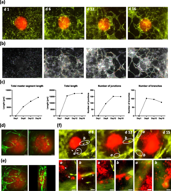
In a next step, we investigated how the bioprinted soft tissue interacts with neuroblastoma tumor spheroids that were embedded during the printing process. Recently, the Kurreck lab described a 3D bioprinted tumor model that combines a neuroblastoma cell line with a renal microenvironment for drug testing [31]. In our experiments, we generated spheroids from patient-derived high-stage neuroblastoma tumors (STA-NB15 cells) that were retrovirally infected to express red-fluorescent mCherry protein (NB15/mCherry). These cells were grown in a low-attachment V-bottom 96-well plate to form spheroids. Spheroids were resuspended in 10 µl collagen type I solution (3 mg ml−1) and transferred into the area between channels of bioprinted tissue chips during the printing process. Thereby, neuroblastoma tumors are embedded into vessel-promoting bioink, which serves as a 3D tumor-environment. Within 6 d of culture the endothelial cells formed a vessel network around the tumor which matured into larger vessels until day 12 and persisted until day 16 (figure 6(a)). As demonstrated by confocal microscopy, dense vessel structures not only formed outside the neuroblastoma spheroid but some sprouting vessels also invaded the spheroid (optical sections from top to bottom (figures 6(d)) and 3D model from confocal z-stack (figure 6(e) and supplemental movie M3). We observed two different fates of spheroids during post-printing culture: many spheroids did not significantly increase in size during two weeks of culture, although newly formed vessels grew towards and in part into these spheroids (figures 6(a) and (d)). This is similar to encapsulated, more benign tumors in patients. The second phenotype mimicked an early metastatic tumor, as red fluorescent tumor cells left the spheroid around day 8 and migrated in part along vessel structures (white arrows) into microvessel knots around the spheroid. In these tissues, the tumor lost its spheroid shape, grew and infiltrated the surrounding tissue (figure 6(f)).
Figure 6. Angiogenesis and tumor cell migration in neuroblastoma tumorenvironment. A red fluorescent neuroblastoma spheroid (NB15/mCherry) was embedded into the soft tissue between branched channels. Dense microvessel networks are formed around the spheroid by green fluorescent endothelial cells and persist for 16 d (a). Vessel networks were analyzed by the Angiogenesis Analyzer plugin for ImageJ (processed images are in gray-scale). Master segments are marked in yellow, branches in green, segments in magenta, isolated segments in blue and meshes in cyan (b). Quantitative analyses of segments and branching are shown in (c). Single optical planes acquired by spinning disk confocal microscopy (10× objective) of the vascularized spheroid on day 7 are shown from top to bottom in figure (d). A z-stack of confocal images was processed into a rotated 3D model (e). When spheroid integrity is lost (f), cells begin to migrate towards vessels between day 5 and day 8 (white arrows). At day 12 and day 15 significant vessel infiltration is visible and disrupted spheroids show increased growth compared to spheroids that maintain shape and structure (upper images, scale bar 200 µm). Specific areas (white cycles) are shown as magnified images ((f), lower panels, size marker 50 µm).
Download figure:
Standard image High-resolution image
It is not clear, which mechanism defines whether a spheroid remains spheroidic or if it enters into a metastatic phenotype—this is currently under investigation in our lab. In both phenotypes, however the neuroblastoma spheroids attracted microvessels from the surrounding soft tissue and mimicked mechanisms of tumor-angiogenesis and metastasis. Thus, this neuroblastoma model in fluidic chip devices represents a novel platform for studying the interplay between tumor tissue and its environment.
3. Discussion
In this project, we present a strategy to produce fluidic chips that contain bioprinted, perfused and micro-vascularized models for neuroblastoma tumors. Our main objective was to manufacture fluidic chip devices as well as tumor tissue models on a standardized, medium-throughput level for drug validation studies. Our acryl chips provide a stable shell for the bioprinted tissue and are designed for paralleled, perfused long-term culture—the perfused bioprinted tissue in the chip contains conduits and is two millimeters thick, thereby mimicking the conditions of native tissue much better than the usual micrometer-sized tissue layers in microfluidic chip. As most convenient strategy, we identified laser engraving/cutting to produce standardized acryl chips that are bonded to glass slides via a biocompatible adhesive tape. This minimizes 'hands-on' time, as higher numbers of specifically engraved chips are manufactured from a larger acryl sheet in one run. Further, laser engraving allows specific surface micro-patterning and circumvents more sophisticated etching and bonding techniques that are usually used for fluidic chip manufacturing. Thus, this methodology should be better accessible to many scientists. The main challenge of full-size 3D bioprinted tissue surrogates is to preserve stability of the hydrogel during cultivation and tissue maturation. Hydrogel contraction, ECM remodeling and matrix degradation must be considered when a bioink for a specific tissue is developed. When culturing bioprinted tissue in acryl chips for two to three weeks, we observed that due to contracting forces in the living tissue, the cell-containing hydrogel detached from walls, which in turn disrupted perfusion channels. This problem was solved by modifying the chip design to stably anchor the hydrogel during polymerization in the acryl shell (figure 1), which prevented detachment and rupture of the supply channels. Further strategies to improve the tissue-to-acryl interface, such as additional surface activation by plasma treatment, chemical activation and coating with ECM molecules are currently tested.
A major challenge in bioprinting is the development of an appropriate bioink that can be printed and polymerized without hampering the viability of embedded cells. The biomatrix has to provide appropriate cell adhesion motives for the different cell types embedded in the bioink, matrix metalloproteinase recognition sequences so that cells can degrade and remodel the matrix, rigidity and tensile strength to assure cell viability, migration and cell differentiation during post-printing tissue maturation (reviewed in [32, 33]). To identify a hydrogel composition that is of sufficient low viscosity to be printed via cell friendly micro-jet heads and on the other hand supports the survival of fibroblasts, endothelial cells and MSCs as well as promotes spontaneous vessel formation we tested a number of different gel compositions and media. A blend of fibrinogen/factor XIII and 5% GelMA in EGM2 medium containing EGF, bFGF, VEGF165 and other factors proved best in respect of printability and vessel formation (figure 3). Gelatin as a proteolytic degradation product of collagen has a tunable mechanical stability, provides motives for adhesion and proteolytic cleavage and, when methacylated, is efficiently polymerized in presence of the photo-crosslinker lithium phenyl(2.4.6-trimethylbenzoyl)phosphinate (LAP) by UVA and violet light [3]. This is essential for layer-by-layer fabrication of living tissue structures. Enzymatically cross-linked fibrinogen including factor XIII adds additional binding motives for endothelial cells and MSCs and promotes angiogenesis [34, 35]. For the construction and long-term cultivation of larger 3D tissue equivalents, solely fibrin-based hydrogels are too instable and short-lived [11]. Therefore, in combination with 5% GelMA, the mixture of fibrin and factor XIII alters the hydrogel stiffness and plasticity, which favors vessel formation and vascular remodeling.
The coating of tissue channels with endothelial cells also proved to be challenging, as endothelial cells did not efficiently adhere to untreated conduit walls. Pre-coating with 10 µg ml−1 fibronectin did not significantly improve adhesion of endothelial cells to this specific bioink (data not shown), whereas incubating the channels with 0.3 mg ml−1 collagen type I solution for 1 h achieved sufficient ECM surface coating. Apparently, partly denaturated collagen fibers polymerize when getting in contact with the matrix surface and form a thin layer on inner channel walls without clotting the channels. However, what remained was the problem of an inefficient cell adhesion to the channel side-walls and channel ceiling. Since manual upside-down flipping of the chips achieved only partial coverage (figure 2(b)) we developed a chip-holder for 12 chips and a specific orbital shaker that halts rotation at defined positions to allow cell adhesion (figure 2(a)). This procedure also demonstrates the advantage of the standardized tissue-on-chip model, as not only manufacturing and bioprinting, but also handling and paralleled post-printing treatments can be standardized.
Several groups investigated the relevance of MSCs from various sources (BM-MSC, ADSC) for the formation of functional vascular networks [2–6], which is especially relevant for mimicking the tissue environment of solid tumors [36, 37]. MSCs support micro-vessel formation by wrapping themselves around the newly formed endothelial cell tubes and differentiating into pericytes and vascular smooth muscle cells, as indicated by the expression of e.g. smooth muscle actin [2, 3, 6]. At least in our bioink the presence of MSCs (or fibroblasts) is also critical for the survival of endothelial cells (figure 3(a) and supplemental figure S6), suggesting that these additional cell types produce essential growth factors and/or ECM molecules which are not provided by the bioink. ADSCs are isolated from left over material from surgery and are in principle available in large amounts. However, there are disadvantages when using primary ADSCs such as variable differentiation potential and limited availability, which revealed to be a significant problem during corona pandemic. Since our goal is the development of patient-specific tumor tissue models that also include immune cells, we tested whether human iPSC-derived mesenchymal-like stem cells can replace ADSCs in terms of micro-vessel formation in bioprinted tissue. iPS-MSCs demonstrated a tri-lineage differentiation potential comparable to primary ADSCs (figures 5(a) and (b)) and promoted vessel formation even at a high passage (figure 5(c)). Thus, iPS-MSCs can serve as a standardized cell source to improve the reproducibility of the model and overcome drawbacks of primary ADSCs from different donors. Furthermore, they can be combined with iPS-derived endothelial cells [6], smooth muscle cells [38], fibroblasts [39] and immune cells [40, 41] to constitute fully patient-specific, complex tissue models for precision medicine applications.
Finally, we tested how patient-derived neuroblastoma tumor spheroids interact with this vascularized soft tissue equivalent and observed recruitment of micro-vessel networks and cases of early metastasis. Since the spheroids were transferred in denaturated collagen solution the collagen fibers slowly renaturate upon contact with the cell laden hydrogel. Thereby, a less rigid collagen matrix surrounds the tumor resembling native tumor microenvironment [42], which might promote endothelial vessel sprouting [43]. Solid spheroids of around 500 µm diameter likely contain hypoxic and nutrient deprived areas, which might trigger the release of pro-angiogenic factors. Consistent with this assumption, we observed significant growth of endothelial cell networks around and into the spheroids (figures 6(a) and (b)). Surprisingly, despite microvessel formation, spheroids that remained in a rounded shape did not grow markedly thereby mimicking a more benign tumor phenotype. In other spheroids, tumor cells left the spheroid and migrated towards clusters of endothelial cells already after few days thus spreading into the neighboring tissue and vessel structures (figure 6(f)). As the same patient-derived neuroblastoma cells show these different phenotypes it is not clear, whether a metastatic phenotype results from e.g. mechanical damage of the spheroid during embedding, tumor-intrinsic factors or slight differences in the composition of the tumor environment. Concerning the tumor environment it will be interesting to see, whether ADSCs from different donors modulate the decision between benign and metastatic phenotype, possibly also in an age- or gender-related manner. These questions are currently under investigation and underline the importance to standardize the cellular components of the bioprinted neuroblastoma-on-chip model by using e.g. iPSC-derived MSCs.
4. Conclusion
In the present paper, we describe a strategy to combine 3D bioprinted tissue models with fluidic chip devices to set up a platform for medium-throughput, high-content neuroblastoma tumor studies and drug validation. Laser-manufacturing of acryl chips minimizes the required manual steps during chip production and generates devices that serve as standardized receptacles for bioprinted tissue. Bioprinted tissue equivalents offer significant advantages over conventional microfluidics as tissue geometry, deposition of specific cell types, cytokines or ECM components are reproducible and larger tissue models can be generated that better resemble micro-environmental conditions of human tissue. Optimized chip design for improved tissue-anchorage during long-term culture, new procedures and tools for the coating of conduits with endothelial cells and a photo-cured stem-cell bioink that promotes spontaneous vessel formation in the matrix constitute a platform for studying tumor—tumor environment interaction. Patient-derived neuroblastoma spheroids efficiently attracted micro-vessels thus resembling in vitro tumor-angiogenesis, but also exhibited a metastatic phenotype and thereby raise new questions concerning the underlying mechanisms. The flexible chip-based design allows us also to combine different bioprinted organ models either on one chip or in one perfusion circuit to assess e.g. far distance metastasis into lung tissue or first-pass metabolism of liver tissue during drug treatment. Thus, the developed bioprinted tissue-on-chip platform offers large flexibility also for small research groups, will significantly advance in vitro drug discovery and contribute to the replacement of animal experiments in scientific research and drug validation.
5. Material and methods
5.1. Cell lines, culture conditions, and reagents
The HUVEC line, (ATCC® CRL-1730™) and HDMEC,(ATCC PCS-110-010™) were cultured with Ham's F-12 K (Kaighn's) medium (Thermo Fisher Scientific, Waltham, USA) supplemented with 30 µg ml−1 endothelial cell growth supplement (ECGS), and 100 µg ml−1 heparin. Human fibroblast cells (ATCC®, PCS-201-010) were cultured in DMEM, high glucose (Thermo Fisher Scientific, Waltham, USA). The neuroblastoma cell line STA-NB15 [44, 45] was cultured in RPMI1640 (Lonza, Basel, Switzerland). STA-NB15 cells were isolated from diagnostic left-over material at the St. Anna Children Hospital, Vienna, with written consent from patient's parents. All media contained 10% fetal bovine serum (GIBCO BRL, Paisley, UK), 100 U ml−1 penicillin, 100 mg ml−1 streptomycin and 2 mM L-glutamine (Lonza,Basel, Switzerland) at 5% CO2.
Primary ADSCs were isolated from adipose tissue from abdominoplasties at the Department of Plastic and Reconstructive Surgery, Medical University of Innbruck. The study was approved by the ethics commission with the reference number AN2014-0244. ADSCs were cultured up to passage number 15 in DMEM/F12 (Dulbecco's Modified Eagle Medium/Nutrient Mixture F-12, Thermo Fisher Scientific, Waltham, USA) supplemented with 2.5% FBS, 10 ng ml−1 rhEGF, 5 ng ml−1 rhFGF2 (ImmunoTools, Friesoythe, Germany) and 10 µg ml−1 insulin.
Human iPS cells were provided by the Helmholtz Center Munich, iPSC Core Facility, Neuherberg, Germany. The iPS cell lines HMGU#1 and HMGU#8 were cultured in StemMACS™ iPS-Brew XF (Miltenyi Biotec, Bergisch Gladbach, Germany). Cells were passaged 1:10 every 3–5 d with Accutase® solution and 10 µM ROCK inhibitor Y27632 (STEMCELL Technologies, Köln, Germany) for the first 24 h on Geltrex™ (Thermo Fisher Scientific, Waltham, USA) coated six-well tissue culture plates.
All cultures were routinely tested for mycoplasma contamination using the VenorR GeM-mycoplasma detection kit (Minerva Biolabs, Germany).
5.2. Expression vectors and genetically modified cell lines
Culture of PhoenixTM packaging cells for helper-free production of amphotropic retroviruses and retroviral infection was described previously [46–48]. The retroviral vector pLIB-mCherry-iresPuro was used to retrovirally infect NB15 cells (NB15/mCherry). The vector was created by cloning the mCherry coding sequence from pQCXIN-mCherry-Tubulin-iresNeo (donated by S Geley) into the EcoR1 and BamH1 sites of the retroviral vector pLIB-MCS2-iresPuro [45]. The retroviral vectors pLIB-hTert-CMVpuro, pLIB-ECFP-iresPuro [49], and pQCXIN-EYFP-iresNeo (donated by S, Geley) were used for the generation of HFF/hTert-ECFP and HUVEC/hTert-EYFP cells, respectively.
5.3. iPS-MSC differentiation and characterization
Differentiation of iPS cells (HMGU#1 and HMGU#8) into mesenchymal-like stem cells (iPS-MSC) was done according to the protocol of Hynes et al [30]. For differentiation, we used minimum essential medium eagle alpha modification supplemented with 10% FBS, 100 μM L-ascorbic acid phosphate, 1 mM sodium pyruvate (Thermo Fisher Scientific, Waltham, USA), 1x MEM NEAA (Thermo Fisher Scientific, Waltham, USA), 100 U ml−1 penicillin, 100 mg ml−1 streptomycin and 2 mM L-glutamine. 80% confluent iPS colonies in a six-well tissue culture plate were detached with 0.5 ml EDTA solution (Thermo Fisher Scientific, Waltham, USA) for 5 min at 37 °C. Cells were collected with 2 ml medium and centrifuged at 300 g for 3 min. The pellet was carefully re-suspended in 2 ml medium and transferred into gelatin-coated six-well plates at a ratio of 1:1. After 14 d of differentiation cells were collected with AccutaseTM solution and split in a ratio of 1:3 into 0.1% gelatin-coated tissue culture dishes. After the first passage, uncoated dishes were used for serial passaging. After five passages an MSC-like population was obtained and characterized by functional three lineage differentiation into adipocytes, osteoblasts and chondrocytes.
Adipocyte differentiation was performed with the StemPro® adipogenesis differentiation kit and osteoblast differentiation with the StemPro® osteogenesis differentiation kit (Thermo Fisher Scientific, Waltham, USA) according to manufacturer protocols. For adipogenesis 25 000 cells/well and for osteogenesis 10 000 cells/well of iPS-MSCs or primary ADSCs were seeded in triplicate in 96-well plates and cultured for 3 weeks with differentiation or control medium. Medium was changed every 3–4 d. Cells were fixed with ROTI®Histofix (Carl Roth, Karlsruhe, Germany) for 15 min at RT and washed with PBS. For adipocyte staining a stock solution of 0.5% oil-red-O (ORO) dye in 100% 2-propanol was diluted 3:2 with deionized H2O (dH2O) and sterile filtered via a 0.2 µm syringe filter. Cells were stained with ORO for 15 min at RT and washed with dH2O twice. 0.2% alizarin red dye was dissolved in dH2O and the pH was adjusted to 4.2. Osteoblasts were stained for 1 min at RT and washed five times with PBS. Chondrocyte differentiation was performed according to the protocol of Solchaga et al [50]. After three weeks of differentiation chondrocyte pellets were fixed with ROTI®Histofix (Carl Roth, Karlsruhe, Germany) for 30 min at RT and were embedded in HistoGelTM (Thermo Fisher Scientific, Waltham, USA). Samples were dehydrated in a graded ethanol series (50%, 70%, 90% and 100%, 5 min each) and then embedded in paraffin. 10 µm sections were de-paraffinized with ROTI®Histol (Carl Roth, Karlsruhe, Germany), rehydrated to water and stained with sterile-filtered 0.1% toluidine blue dye in dH20 for 2 min. Stained cells were imaged with a Zeiss Axiovert200M microscope (Zeiss, Oberkochen, Germany).
5.4. GelMA functionalization
GelMA functionalization was adapted from a protocol from Loessner et al [13]. Briefly, 30 g gelatin (gelatin from porcine skin, type A,) was dissolved in 300 ml dH2O at 50 °C. Eighteen grams methacrylate were added dropwise during constant stirring and gelatin was functionalized for 3 h at 50 °C in the dark. Then the solution was centrifuged for 5 min at 3.600 g at 25 °C. The supernatant was diluted 1:1 with pre-warmed dH2O and dialyzed with a MWCO 6–8.000 Spectra/PorTM dialysis membrane (Fisher Scientific U.K. Limited, Loughborough, UK) against water for 7 d with daily water exchange at 50 °C in the dark. The pH was adjusted to 7.4 with 1 M NaHCO3 and the GelMA solution was sterile filtered with a 0.4 µm aPES bottle top filter (Thermo Fisher Scientific, Waltham, USA). The GelMA solution was snap-frozen with liquid nitrogen, lyophilized and stored at −80 °C for long-term storage up to one year.
5.5. Chip manufacturing
Chips were laser cut from 2 mm PMMA (Laser Cutter Mini, Epilog Laser, Colorado, USA). The chip design shown in figure 1(b) was created with CorelDraw Graphics Suite software (Corel Corporation, Ottawa, Ontario, Canada). Different colors define cutting or engraving procedures (red lines: cutting; green, blue and magenta: engraving settings are summarized in table 1). The chips were bonded to glass coverslips (26 × 21 mm, Menzel, Thermo Fisher Scientific, Waltham, USA) with biocompatible adhesive tape (ARcare 90106NB, Adhesive Research Inc., Pennsylvania, USA) [51], sonicated for 20 min, boiled twice in dH2O for 5 min and sterilized in 70% ethanol overnight.
Table 1. Settings for laser cutter Mini Epilog Laser.
| Color code | Speed | Power | Frequency | Grid |
|---|---|---|---|---|
| Red | 15% | 60% | 5000 | No |
| Green | 10% | 100% | 5000 | Yes |
| Blue | 80% | 60% | 5000 | Yes |
| Magenta | 80% | 40% | 500 | Yes |
5.6. 3D bioprinting on-a-chip
5% (wt/vol) GelMA and 0.5% LAP were dissolved in 50% of the final volume in cell culture medium at 37 °C for 3 h. After dissolving, the hydrogel was further soaked overnight at 4 °C. Prior to printing, the hydrogel was incubated for 3 h at 37 °C. Fibrinogen and thrombin (TISSEEL, Baxter Healthcare GmbH, Vienna, Austria) were thawed at RT and diluted in sterile PBS with 40 µM CaCl2. Fibrinogen was added to the hydrogel to a final concentration of 2.5 mg ml−1. HUVEC/hTert-EYFP and primary ADSCs were added to the hydrogel to obtain 10 × 106 cells ml−1 and 7.5 × 10⁶ cells ml−1 respectively (Ratio 1:0.75). The cell-laden hydrogel was printed with a micro-jet printhead at a pressure of 20 kPa and a feed-rate of 15 mm s−1 directly into the chip (CF300H, 3D Discovery BioSafety, RegenHu, Villaz-Saint-Pierre, Switzerland). Each printed layer was cross-linked for 5 s with the integrated light curing system (365 nm, 360 mW). Channel structures were printed via direct-dispensing with the thermo-sensitive material Pluronic F-127. 3.5 g Pluronic F-127 dissolved in 10 ml sterile 0.9% NaCl at 4 °C overnight are printed with a 20 G, 1" needle (Gonano Dosiertechnik, Breitstetten, Austria) at 20 °C with 180 kPa pressure and 2 mm s−1 feed-rate. Neuroblastoma tumor spheroids (NB15/mCherry) were grown in a 96-well V-bottom microplate to a diameter of 400–500 µm and manually placed between the printed channels with 10 µl collagen type I solution (Arthro Kinetics Biotechnology, Krems an der Donau, Austria). Next, three layers of cell-laden hydrogel were printed on top of the channels. The chip and the inlets were covered with an additional layer of cell-free hydrogel (5% GelMa, 0.5% LAP) and finally cross-linked for 2 min with a custom-build LED array (390–400 nm, 6500 µW cm–2). The fibrinogen component in the hydrogel was cross-linked with 3 ml of a 2 U ml−1 thrombin solution at 37 °C for 20 min. The chips were cultured in 2.5 ml EGM2 medium (PromoCell, Heidelberg, Germany) at 37 °C, 5% CO2 in six-well plates with medium change every second day.
5.7. Live cell and confocal imaging
Images were collected with an Axiovert200M microscope equipped with filters for ECFP (Ex: BP436/20, Em: BP480/40), EYFP (Ex: BP500/20, Em: BP535/30) and mCherry/RFP (Ex: BP550/32Bl-HC, Em: LP590) and diverse objectives ranging from 63× oil to 5× (Zeiss, Oberkochen, Germany). Live confocal microscopy was done on an inverted microscope (Zeiss Observer.Z1; Zeiss, Oberkochen, Germany) in combination with a spinning disc confocal system (UltraVIEW VoX; Perkin Elmer, Waltham, MA, USA) with a 10× objective or an Operetta CLS High Content Analysis System (Perkin Elmer, Waltham, MA, USA) with a 20× objective. Image analyses were done with Axiovision Software (Zeiss, Oberkochen, Germany).
5.8. Immunofluorescence of cells and tissue
Cells were seeded into eight-well μ-slides with glass-bottom (Ibidi, Gräfelfing, Germany) coated with 0.1 mg ml−1 collagen (Corning, New York, USA) and cultured until confluence. Cells were fixed with 4% ROTI®Histofix (Carl Roth, Karlsruhe, Germany) for 15 min and permeabilized with 0.1% TritonX-100. After blocking with 2% bovine serum albumin and 1% fetal bovine serum, CD31-antibody (1:1600, Cell Signaling, Boston, MA, USA) or VE-cadherin antibody (1:200, LifeSpan BioSciences, Washington, USA) were added, incubated overnight and after a washing step detected with anti-mouse or anti-rabbit-AlexaFluor488 FITC-conjugated secondary antibody (1:1500, Invitrogen, Waltham, USA), respectively. Nuclei were stained with 100 nM Hoechst33342 dye (Sigma-Aldrich, St. Louis, USA).
3D bioprinted tissue was fixed with 4% ROTI®Histofix (Carl Roth, Karlsruhe, Germany) for 16 h. Samples were washed in PBS and dehydrated in a graded ethanol series (50%, 70%, 90% and 96%, 45 min each and 100% for 16 h). Samples were transferred to ROTI®Histol (Carl Roth, Karlsruhe, Germany) for 2 h and then embedded in paraffin. 8 µm sections were de-paraffinized with ROTI®Histol, rehydrated and washed in PBS. Antigens were unmasked by cooking the samples with 10 mM citrate buffer (pH6) in a microwave for 20 min. Slides were blocked and permeabilzed with 1% bovine serum albumin, 2% fetal bovine serum and 0.1% Triton X-100 for 45 min. Auto fluorescence was blocked with filtered 0.1% Sudan Black B/ 70% ethanol solution for 30 min. After washing with PBS, cells were incubated with CD31-antibody (1:200, Cell Signaling, Boston, MA, USA) or VE-cadherin antibody (1:100, LifeSpan BioSciences, Washington, USA), washed and incubated with anti-mouse or anti-rabbit-AlexaFluor488 FITC-conjugated secondary antibody (1:200, Invitrogen, Waltham, USA), respectively. Nuclei were stained with 100 nM Hoechst33342 dye (Sigma-Aldrich, St. Louis, USA) and embedded with fluorescence mounting medium (Dako North America, California, USA).
5.9. Channel coating
3D tissue chips were printed with 15 × 106 HFF/hTert-ECFP cells/ml in the cell-laden hydrogel as described before. After cultivation for 7 d channels were pre-coated with 0.3 mg ml−1 collagen type I (Arthro Kinetics Biotechnology, Krems an der Donau, Austria) in 20 mM acetic acid for 1 h at 37 °C with a custom-built orbital shaker. The channels were washed with PBS and coated with 30 µl HUVEC/hTert-EYFP cells (30×106 cells ml−1) in EGM2 medium for 90 min in the orbital shaker. The chips were cultured in EGM2 medium with medium change every second day. The barrier function was tested after 4 d by perfusion with 0.25 mg ml−1 70 kDa dextran-rhodamine B conjugate. Channels were filled with 30 µl dextran-rhodamin solution and the diffusion into the matrix was imaged in the following 30 min by fluorescence microscopy. The increase of fluorescence intensity in the matrix was quantified using Axiovision Software (Zeiss, Oberkochen, Germany) and expressed as a percentage compared to uncoated control chips.
5.10. Scanning electron microscopy
3D bioprinted tissue models were washed with PBS and fixated for 24 h at 4 °C in 3 ml of 2.5% glutaraldehyde. The models were dehydrated with a graded ethanol series (50%, 70%, 90% and 100%, 5 min each) and left to dry out for 1 h in a biosafety cabinet. The dried models were placed on aluminum pins and were sputtered with gold (Agar Sputter Coater, Agar Scientific Ltd, Stansted, GB, UK) for 1 min and analyzed by SEM (JSM-6010LV, JEOL GmbH, Freising, Germany).
5.11. Statistics and data analyses
Fluorescence images were processed in Fiji software, a distribution of ImageJ [52]. Total master length, branching and total length of vessel networks were quantified with the Angiogenesis Analyzer plugin for ImageJ [28]. Data were analyzed in GraphPad Prism 8 software. Standard deviation (SD) and Student's t-test (two-tailed, with criteria of significance: *p < 0.05; **p < 0.01, ***p < 0.001 and ****p < 0.0001) were calculated when applicable.
Acknowledgments
We thank V Jeller, N Kaiser and S Lobenwein for technically support and Dr S Geley for donating plasmids. For providing hiPS cell lines HMGU#1 and HMGU#8 we thank Dr M Drukker HMGU iPSC Core Facility, Helmholtz Zentrum München, Germany. We would also like to thank Arthro Kinetics Biotechnology GmbH for providing us medical-grade collagen. Funding was received from the Austrian Science Fund (I3089-B28 and FG15), the Austrian Research Promotion Agency (Bridge-1 880666), the 'Dr Johannes und Herta Tuba-Stiftung', the intramural funding program of the Medical University Innsbruck Project PTF 2020-1-4, the Federal Ministry Republic of Austria for Education, Science and Research (Project 'Replacement of animal experiments in science'), the 'Kinderkrebshilfe Tirol und Vorarlberg', and the 'Tirol-Kliniken GmbH'.
Data availability statement
All data that support the findings of this study are included within the article (and any supplementary files).
Author contributions
Study design and concept: J H, M J A, D N; data acquisition and analysis: D N, D W, P C, D H, M H, J H, M J A; drafting the manuscript: D N, J H, T M, M J A; Funding: J H, M J A; All authors read and approved the final manuscript.
Conflict of interest
There are no conflicts to declare.