
Abstract
Recent advances in additive manufacturing (AM) technologies provide tools to fabricate biological structures with complex three-dimensional (3D) organization. Deposition-based approaches have been exploited to manufacture multimaterial constructs. Stimulus-triggered approaches have been used to fabricate scaffolds with high resolution. Both features are useful to produce biomaterials that mimic the hierarchical organization of human tissues. Recently, multitechnology biofabrication approaches have been introduced that integrate benefits from different AM techniques to enable more complex materials design. However, few methods allow for tunable properties at both micro- and macro-scale in materials that are conducive for cell growth. To improve the organization of biofabricated constructs, we integrated direct ink writing (DIW) with digital light processing (DLP) to form multimaterial constructs with improved spatial control over final scaffold mechanics. Polymer–nanoparticle hydrogels were combined with methacryloyl gelatin (GelMA) to engineer dual inks that were compatible with both DIW and DLP. The shear-thinning and self-healing properties of the dual inks enabled extrusion-based 3D printing. The inclusion of GelMA provided a handle for spatiotemporal control of cross-linking with DLP. Exploiting this technique, complex multimaterial constructs were printed with defined mechanical reinforcement. In addition, the multitechnology approach was used to print live cells for biofabrication applications. Overall, the combination of DIW and DLP is a simple and efficient strategy to fabricate hierarchical biomaterials with user-defined control over material properties at both micro- and macro-scale.
Export citation and abstract BibTeX RIS

Original content from this work may be used under the terms of the Creative Commons Attribution 4.0 license. Any further distribution of this work must maintain attribution to the author(s) and the title of the work, journal citation and DOI.
1. Introduction
Additive manufacturing (AM) and biofabrication are increasingly leveraged in biomedical engineering to fabricate biological constructs with complex three-dimensional (3D) organization that mimic the structure and function of native tissues [1, 2]. 3D-printed constructs are applied as disease models to better understand pathology, as reproducible microtissues to screen or test new therapeutics, or directly as devices to repair or regenerate tissues [3–8]. Traditional approaches for AM of tissue constructs and biomedical devices can be grouped into two broad subcategories based on their mechanism of fabrication—deposition-based AM or stimulus-triggered AM [9–12]. Each approach provides specific advantages for the digital fabrication of complex biomaterials.
Deposition-based AM enables rapid production of multimaterial constructs [13]. Direct ink writing (DIW) is a common biofabrication technique that builds 3D objects by depositing one or multiple biomaterials at specific locations via robotic dispensing [1, 9, 10]. DIW often requires biomaterial inks with suitable rheology to enable low pressure extrusion and shape retention [14]. Hydrogel-based inks with shear-thinning and self-healing properties are used to reduce shear-stresses during extrusion and increase shape retention post-fabrication. Even with proper ink design, the inclusion of shear-sensitive components in the bioink, such as mammalian cells, constrains the smallest nozzle diameter (Ø ∼ 200–300 µm). Smaller diameter nozzles result in increased shear stress and compromised viability [15, 16]. Because of this constraint, the resolution of deposition-based biofabrication remains one of its main limitations.
Several stimulus-triggered AM technologies allow for biofabrication with micron-scale resolution [17–19]. In general, stimulus-triggered AM provides a stimulus (e.g. binder solution or focused light) at specific locations to solidify or cure a material reservoir (e.g. powder bed or photocurable resin) with spatiotemporal control [20–23]. Notably, digital assembly with light offers high spatial resolution (micron- or sub-micron-scale; diffraction limited) and temporal control over material curing [24]. For example, visible light was used as a cytocompatible stimulus to fabricate cell-laden, 3D objects with micron-scale resolution [25]. Further, photocurable resins can exhibit rapid cross-linking kinetics, allowing for high speed and continuous manufacturing [26–28]. However, a limited number of cytocompatible resins are available for light-based biofabrication in the presence of cells [5, 29]. In addition, it can be challenging to produce multimaterial constructs as a change in resin bath is required for each new material. As such, few examples have used light to bioprint multimaterial scaffolds with high resolution [30, 31].
As a whole, these AM technologies provide a range of printing resolutions and materials suitable to biofabricate tissue mimics or implants. However, few individual technologies enable patterning and control over material composition at both micro- and macro-scale. As both deposition-based and stimulus-triggered technologies provide distinct advantages (multimaterial constructs and high resolution, respectively), researchers have integrated different AM techniques for multitechnology biofabrication that address one or more limitations of a single technology approach [32]. For example, fused deposition modeling (FDM) was combined with digital light processing (DLP) to form hybrid tissue constructs [33]. To produce structurally reinforced, human-scale tissue constructs, FDM of thermoplastic support materials was combined with DIW of cell-laden hydrogels [34]. More recently, a hybrid 3D printer was introduced that integrated DIW for multimaterial printing with DLP for high resolution patterning to design composite materials, soft robots, and soft electronics [35]. In this work, disparate materials were used and processed independently based on the technology used for that part of the final construct, either DIW or DLP. Further, this approach was not demonstrated for biofabrication of 3D constructs with encapsulated cells. In general, hybrid AM approaches are promising as they can fabricate complex constructs with hierarchical material organization that ranges from the micron to meter scales [36]. However, these hybrid approaches have not been applied for hierarchical biofabrication of fully hydrogel-based biomaterials, which are the main class of materials used for biofabrication as they recapitulate critical features of the extracellular matrix. Further, these approaches did not enable simultaneous processing of individual bioinks for control over material properties at different length scales.
In this work, we present a facile approach to fabricate hierarchical biomaterials with controlled properties at both micro- and macro-scale. Our strategy integrated DIW to print multimaterial scaffolds with DLP to cure the deposited biomaterial and tailor the local mechanics of the printed construct with ∼100 µm resolution. The approach relied on the formulation of dual bioinks with shear-thinning and self-healing properties that enable subsequent photopolymerization. To prepare dual bioinks, we combined our univeral nanocarrier ink (UNI) platform [37], based on polymer–nanoparticle (PNP) hydrogels, with methacryloyl gelatin (GelMA). The rheological properties were amenable to printing, independent of the GelMA concentration, and the final mechanics of the structures were tailored and patterned (binary or grayscale images) via DLP, exploiting photopolymerization of GelMA. The freedom of design enabled by the combination of DIW and DLP allowed for 3D printing of hierarchical biomaterials with tunable mechanical reinforcement and cytocompatible environments for biofabrication.
2. Materials and methods
Hydroxypropylmethylcellulose (HPMC, Mn ∼ 700 k Da; Ref H3785); methacrylic anhydride (Ref 276 685); type A gelatin from porcine skin (Ref 9000-70-8); acryloxyethyl thiocarbamoyl rhodamine B (Ref 908 665); formaldehyde solution 4%, buffered, pH 6.9 (Ref 1004 968 350); 2,4,6-trimethylbenzoyl chloride (Ref 682 519); dimethyl phenylphosphonite (Ref 149 470); lithium bromide (Ref 213 225), poly(ethylene glycol) methyl ether (Ref 81 323); toluene (Ref 244 511); tin (II) 2-ethylhexanoate (Ref S3252); 4',6-diamidino-2-phenylindole dihydrochloride (DAPI, Ref D9542), and 3,6-dimethyl-1,4-dioxane-2,5-dione (Ref 303 143) were purchased from Sigma–Aldrich (Buchs, Switzerland). Minimal essential medium with alpha modification and nucleosides (Ref 22 571-020), penicillin–streptomycin (PS) (10 000 U ml−1; Ref 15 140-122), fetal bovine serum (FBS) (Ref 10 270 106), LIVE/DEAD Viability/Cytotoxicity kit (Ref L3224), and AlexaFluor 488 Phalloidin (Ref A12379) were purchased from ThermoFisher (Basel, Switzerland). Recombinant human FGF-basic (FGF-2, Ref 100-18B) was purchased from PeproTech (London, UK).
1H NMR spectra were acquired on a Bruker Avance III 400 (Bruker BioSpin GmbH). Chemical shifts were reported relative to the respective solvent peak.
2.1. GelMA synthesis
GelMA was synthesized following established protocols [ 38 ]. Type A gelatin (20 g) was dissolved in dH2O (150 ml) in a round bottom flask and stirred at 50 °C. Methacrylic anhydride (MA, 12 g) was added dropwise to the gelatin solution and the reaction proceeded for 1.5 h at 50 °C. The solution was transferred to 50 ml conical tubes and centrifuged at 3500 rcf for 5 min. The supernatant containing GelMA was decanted into a glass beaker (500 ml) and diluted 1:2 by volume with preheated (40 °C) dH2O. The solution was transferred to dialysis tubing (SnakeSkin TM dialysis tubing, 3.5 kDa MWCO; Ref 88 244, Thermo Scientific) and dialyzed against dH2O at 40 °C for 7 d. The dialysis water was changed twice daily. Later, the solution was diluted 1:10 by volume with preheated (40 °C) dH2O, sterilized over a 0.2 µm filter, frozen (−80 °C) overnight, and lyophilized for 5 d. 1H NMR (D2O) was used to quantify the degree of functionalization (∼70%) by calculating the ratio of the lysine methylene signals (δ = 2.8–3.0 ppm) of GelMA to the phenylalanine signal (δ = 7.1–7.4 ppm) of unmodified gelatin (figure S1 available online at stacks.iop.org/BF/13/044105/mmedia).
2.2. PEG-b-PLA synthesis and NP preparation
PEG-b-PLA was prepared via ring-opening polymerization with tin (II) 2-ethylhexanoate [Sn(Oct)2] as a catalyst using an adapted procedure from literature [39]. The polymerization reaction was performed in an inert and anhydrous environment. Poly(ethylene glycol) methyl ether (5 kDa; 3.5 g, 0.7 mmol) and 3,6-dimethyl-1,4-dioxane-2,5-dione (LA; 11.180 g, 77 mmol) were dissolved in degassed toluene (30 ml) in a three-neck round bottom flask at 100 °C. Upon addition of Sn(Oct)2 (0.32 ml, 0.9 mmol) to the PEG/LA/toluene mixture, the temperature was increased to 140 °C and the reaction proceeded for 6.5 h. Upon completion, the reaction was cooled to room temperature, and the solution was recovered by precipitation from cold diethyl ether, recollected by filtration, and dried under vacuum for 2 d. PEG-b-PLA (7 mg) dissolved in CDCL3 (700 µl) was used for 1H NMR analysis. The molecular weight of the PLA chain was determined by comparing integration values of the CH and CH3 peaks of the PLA repeat units (1.5 ppm and 5.2 ppm, respectively) to the terminal CH3 peak of the PEG chain (3.58 ppm) (figure S2).
PEG-b-PLA nanoparticles (NPs) were prepared via nanoprecipitation as described [40]. In brief, 140 mg of PEG-b-PLA were dissolved in 2.5 ml of acetone and precipitated dropwise in a stirring solution of milliQ H2O (10 ml). The acetone was removed overnight by evaporation, and the NPs were recovered via filtration (Amicon filter, 30 kDa MWCO) at 4500 rcf for 70 min. The filtered NPs (figure S3) were collected and resuspended in PBS at a final concentration of 20 wt% and stored at 4 °C until further use.
2.3. LAP synthesis
Lithium phenyl-2,4,6-trimethylbenzoylphosphinate (LAP) was synthesized as described [41, 42]. In brief, 2,4,6-trimethylbenzoyl chloride (3.2 g, 0.018 mol) was added slowly to dimethyl phenylphosphonite (3 g, 0.018 mol) under argon and stirring at room temperature. The reaction proceeded for 18 h. A solution of lithium bromide (6.1 g, 0.072 mol) in 2-butanone (100 ml) was added to the reaction mixture. To induce product precipitation, the reaction was heated to 50 °C for 10 min and then cooled to room temperature. The solution was filtered to recover the precipitate, washed 3× with 2-butanone (100 ml), and dried under vacuum. Product quality was confirmed via 1H NMR (400 MHz, D2O): δ 7.75 (m, 2 H), 7.59 (m, 1 H), 7.49 (m, 2 H), 6.91 (s, 2 H), 2.26 (s, 3 H), 2.05 (s, 6 H) (figure S4).
2.4. PNP–GelMA hydrogel preparation
UNI–GelMA-5 (HPMC 1 wt%, PEG-b-PLA NPs 15 wt%, GelMA 5 wt%, and LAP 0.1 wt%) and UNI–GelMA-10 (HPMC 1 wt%, PEG-b-PLA NPs 15 wt%, GelMA 10 wt%, and LAP 0.1 wt%) hydrogels were prepared by first dissolving HPMC in PBS at the desired concentration and equilibrating in a syringe overnight (25 °C). GelMA, LAP, and NP solution were loaded at the desired concentrations into a second syringe and kept at 37 °C until further use. Before mixing, the two syringes were centrifuged to remove residual bubbles entrapped in the solution. The syringes were connected by a female-to-female luer lock adapter (Cellink, Sweden) and gently mixed together for 5 min and kept at 37 °C until further use.
2.5. Rheological measurements
Rheological measurements were performed using a strain-controlled shear rheometer (MCR 502; Anton-Paar, Zofingen, Switzerland) equipped with a Peltier stage. A 25 mm cone–plate geometry with a 2° truncation angle was used for all experiments, unless otherwise noted. The experiments were performed at 37 °C and silicone oil was used to isolate the sample during the test to prevent drying.
To investigate the viscoelastic properties of the prepared materials, dynamic oscillatory strain amplitude sweep measurements were performed at a constant angular frequency, ω = 10 rad s−1, and the strain amplitude, γ, was increased from 0.1% to 1000%. Dynamic oscillatory frequency sweep measurements were performed at a γ = 0.3% and the angular frequency, ω, was decreased from 100 to 0.01 rad s−1 (figure S5). Rotational shear rate measurements were performed with initial shear rate dγ/dt = 0.1 s−1 and final shear rate dγ/dt = 100 s−1. The measured viscosity, η, was fit in the linear range (dγ/dt from 1 to 100 s−1) to the power-law model: η = KPL (dγ/dt)n −1 to investigate the shear-thinning index, n, and consistency index, KPL, at different shear rates (table S1). To measure the self-healing properties of the hydrogel inks, dynamic oscillatory time sweep tests were designed with seven intervals of alternating low strain (γ = 0.3%, ω = 10 rad s−1) and high strain (γ = 1000% or 100% for UNI formulation or UNI–GelMA formulations respectively, ω = 10 rad s−1).
An 8 mm plate–plate geometry with 0.5 mm gap size was used for dynamic oscillatory time sweep measurements (γ = 0.3%, ω = 10 rad s−1) to characterize the cross-linking kinetics of UNI–GelMA. The samples were irradiated (λ = 405 nm, I = 10 mW cm−2) after 60 s oscillation to induce photopolymerization of the GelMA (figure S6).
All rheological measurements were performed at least in triplicate (n ⩾ 3).
2.6. DIW and bioprinting
A pneumatic-driven 3D printer (BioX, Cellink) was used for the 3D printing (DIW) experiments. For all tests, 3 ml cartridges mounted with straight nozzles (22 G, Ø = 410 µm) were used with a heated printhead (37 °C). The printing parameters were set for homogeneous flow for both UNI–GelMA-5 (30–35 kPa, 4 mm s−1) and UNI–GelMA-10 (55–65 kPa, 4 mm s−1). The G-code used to print the 3D rectangular structures for the cell encapsulation experiments was written manually. The 3D models of the ETH logo and the meniscus were designed using NX Siemens CAD software and the G-code was generated with BioX internal software.
2.7. DLP
For photopatterning of the constructs, we used a 0.47' digital micromirror device DLP® E4750LC (EKB Technologies Ltd, Israel) with a 405 nm LED light source and 96 mm × 54 mm image size at 118 mm working distance. Based on the display settings (1920 × 1080 micromirrors) and working distance, the pixel size in the printed construct was 50 µm × 50 µm. The grayscale images of Albert Einstein and Marie Skłodowska Curie were downloaded from the internet (https://de.cleanpng.com/png-9069gn/ and https://de.cleanpng.com/png-w8s164/, respectively). The photopatterning geometries were designed in Affinity Publisher and exported as PNG. The DLP device was connected to a portable computer and controlled through a Windows®-based GUI tool (DLP® Pico Display and Light Control EVM, TX Instruments) to display the pattern on the printing plate. The light intensity at the surface of the construct was controlled to be 10 mW cm−2.
2.8. Tensile tests
To test the potential of tailoring the mechanical properties using photopatterning, uniaxial tensile tests were performed on constructs fabricated with UNI–GelMA-10. To eliminate any effect of the extrusion process on the final mechanical properties, the material was molded into rectangular shaped test-pieces (width × length × thickness: 5 mm × 30 mm × 1 mm). Distinct cross-linking times were combined with different pattern geometries to fabricate composite materials. Uniaxial tests were performed as previously described [43]. Briefly, test-pieces were clamped to two axes of a custom-built tensile testing setup (MTS Systems, USA) and elongated at a nominal displacement rate of 0.02 mm s−1. All tensile tests were performed at room temperature with samples immersed in a 0.15 M NaCl bath. From top-view images of the deforming samples, the local in-plane principal stretches λ1 and λ2 were extracted using a custom-written optical flow tracking algorithm [44]. The nominal stress was calculated as P = F/(WH), where F is the measured force, W is the reference width measured from the top-view images during testing, and H is the gel thickness obtained from images of the sample cross-section. The elastic modulus, E, and the Poisson's ratio, v, in the range of small strains were calculated by linear regression of the P − λ1 and λ2 − λ1 curves, respectively, i.e. P = E(λ1 − 1) and (λ2 − 1) = −v(λ1 − 1), using data up to 2% linear strain. Statistical analysis was performed between the matrix condition and the reinforced structures using two-sample t-tests (p < 0.05).
2.9. Cell culture and bioprinting
Human bone marrow‐derived stromal cells (hMSCs) were isolated from bone marrow aspirates of healthy donors obtained during orthopaedic procedures with informed consent and in accordance with the local ethical committee (University Hospital Basel; Prof Kummer; approval date 26 March 2007, Ref Number 78/07). Cells were cultured at 37 °C in a 5% CO2 incubator in minimal essential medium with alpha modification and nucleosides (MEMα) supplemented with FBS (10%) and PS (100 U ml−1). Cells were passaged before reaching 90% confluency and the medium was changed every 2 and 3 d. hMSCs (P7) were added to either UNI–GelMA-5 or UNI–GelMA-10 at a 1:9 ratio to reach a final concentration of 2 × 10⁶ cells ml−1 and gently mixed using a spatula. The mixture was loaded into a preheated (37 °C) 3 ml cartridge mounted with a conical nozzle (Ø = 410 µm).
Bilayer (layer height, 250 µm) rectangular samples (15 mm × 7 mm) were printed with UNI–GelMA-5 using 19–22 kPa pressure at 4 mm s−1 using a pneumatic-driven 3D printer (BioX, Cellink) on a pre-warmed Sigmacote‐coated glass slide. The DLP setup (λ = 405 nm light, I = 10 mW cm−2) was used to photopolymerize the scaffolds. Three conditions were tested for samples prepared with photopatterning-enhanced DIW: (a) uniform partial cross-linking (homogeneous exposure for 10 s); (b) uniform complete cross-linking (homogeneous exposure for 30 s); and (c) stepwise composite cross-linking (homogenous exposure for 10 s followed by patterned exposure for 20 s). Two control conditions were used for nonprinted scaffolds, in which samples were casted between two Sigmacote‐coated glass slides (sample thickness = 0.5 mm). These samples were gelled using (a) uniform partial cross-linking (homogeneous exposure for 10 s) and (b) uniform complete cross-linking (homogeneous exposure for 30 s). All samples were placed in cell culture medium (supplemented with 10% FBS, 1% PS, and 5 ng ml−1 FGF-2) and incubated (37 °C, 5% CO2) until further analysis. The medium was refreshed 15 min after bioprinting or encapsulation, and then once every two days for the duration of culture.
As a representative biological structure, we 3D printed a meniscus using our biofabrication approach. The meniscus construct was printed with UNI–GelMA-10 using 30–35 kPa at 4 mm s−1 and photopatterned (λ = 405 nm light, I = 10 mW cm−2). Three conditions were tested for samples prepared with photopatterning-enhanced DIW: (a) uniform partial cross-linking (homogeneous exposure for 10 s); (b) uniform complete cross-linking (homogeneous exposure for 60 s); and (c) stepwise composite cross-linking (homogeneous exposure for 10 s followed by patterned exposure for 50 s). Two control conditions were used for nonprinted scaffolds, in which samples were casted between two Sigmacote‐coated glass slides (sample thickness = 0.5 mm). These samples were gelled using (a) uniform partial cross-linking (homogeneous exposure for 10 s) and (b) uniform complete cross-linking (homogeneous exposure for 60 s).
Cell viability was analyzed via membrane integrity at days 0, 1, 2 and 5 after encapsulation. A LIVE/DEAD Viability/Cytotoxicity kit (ThermoFisher) was used according to the manufacturer's instruction. In brief, the samples were washed 2× in PBS for 2 min, followed by incubation (37 °C, 5% CO2) in live/dead solution for 1 h. Before imaging (EVOS M5000, ThermoFisher), the samples were washed 3× with PBS for 2 min. Statistical comparison between the samples and at different time points was performed using one-way analysis of variance with Bonferroni comparison of means (p = 0.05). The Shapiro–Wilk test failed to reject the null hypothesis that the sample population was normally distributed (p > 0.05).
Cell morphology was analyzed at days 0 and 5. AlexaFluor 488 Phalloidin (ThermoFisher) and DAPI (Sigma–Aldrich) were used according to the manufacturers' protocols. In brief, the samples were washed 2× in PBS for 2 min followed by overnight fixation in 4% paraformaldehyde solution (4 °C). After fixation, the samples were washed 3× with PBS for 2 min, incubated in the staining solution for 1 h, and again washed 3× with PBS for 2 min before imaging with confocal microscopy (LSM 780, Zeiss).
3. Results and discussion
3.1. Hydrogel formulation for combined DIW and DLP
In this work, we combined DIW and DLP to fabricate scaffolds with hierarchical control over biomaterial composition and mechanical properties (figure 1). This approach required dual bioinks that allowed for both DIW and DLP in a single material. For DIW, an ink with a high viscosity at low shear rate as well as shear-thinning and self-healing properties was necessary to prevent cell sedimentation, to enable flow, and to provide sufficient shape retention for 3D printing [14]. In addition, shear-thinning inks reduce the shear-stress experienced by cells near the nozzle wall, which can improve cell viability [45–47]. In the case of the sequential process used with our multitechnology printing approach, efficient self-healing was needed to preserve the printed shape until further post-curing. For photopatterning via DLP, the ink should enable light-based changes in mechanical properties through the inclusion of reactive groups, e.g. (meth)acrylates, and a photoinitiator [20, 24]. For patterning in the presence of cells, the polymerization conditions should be cytocompatible. Finally, to provide a conducive environment for cell growth, the ink should include cell-binding motifs, such as the RGD peptide sequence, to facilitate cell–material interactions [38].
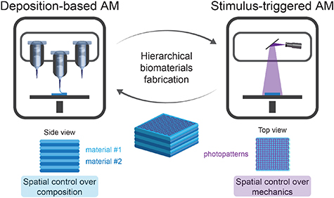
Figure 1. Overview of the multitechnology biofabrication approach that combined DIW (deposition-based AM) with DLP (stimulus-triggered AM) to produce hierarchical biomaterials with multiple materials and photopatterned reinforcement.
Download figure:
Standard image High-resolution imageBased on these design constraints, we formulated dual bioinks by combining our previously developed UNI platform with GelMA. The UNI platform is composed of a PNP hydrogel, in which interactions between HPMC and PEG-b-PLA NPs form a transient physical network with suitable rheological properties for DIW [37]. Previously, the UNI platform was combined with different secondary polymers (e.g. collagen, methacrylated hyaluronic acid, PEG diacrylate, and alginate) to formulate functional and post-curable bioinks with shear-thinning and self-healing properties. In this project, we used GelMA as the secondary polymer (UNI–GelMA) as it is conducive to cell growth and facilitates photopolymerization. Gelatin is a denatured form of collagen that contains cell binding domains, including RGD [48]. The functionalization of gelatin with methacryloyl moieties has been exploited broadly to synthesize photo-curable biomaterials for tissue engineering and bioprinting [24, 49, 50]. We included LAP as the photoinitiator as it can be activated upon exposure to visible light (λ = 405 nm) and is commonly used for cell encapsulation [42].
Formulating GelMA with our PNP-based rheological carrier fluid (UNI platform) generated a dual bioink suitable for DIW and DLP within a single material. Alternative approaches can be used to tailor the viscoelastic properties of GelMA beyond our UNI platform, potentially increasing the spectrum of bioinks compatible with this multitechnology printing approach [51–53].
3.2. Rheological characterization of the dual bioink
The base formulation of the UNI platform consisted of HPMC (1 wt%) and PEG-b-PLA NPs (15 wt%; figure S3). To generate dual bioinks, GelMA was added to the base UNI formulation at either 5 wt% (UNI–GelMA-5) or 10 wt% (UNI–GelMA-10). All photocurable formulations contained LAP (0.1 wt%) as a photoinitiator. Shear rheometry was used to characterize the viscoelastic properties of the different biomaterial ink formulations. GelMA alone (10 wt%; GelMA-10) exhibited liquid-like behavior (G'' > G') at 37 °C, indicating that without a carrier ink this GelMA formulation was not suitable for DIW. In contrast, the UNI formulation displayed solid-like properties (G' > G'') over the whole frequency range tested (figure S5), indicating the formation of a transient physical network based on the formation of a PNP hydrogel (figure 2(a)) [37, 47, 54, 55]. Combining GelMA (5 wt% and 10 wt%) with the UNI platform generated inks that retained solid-like properties; the storage moduli of the inks increased with GelMA concentration (G'UNI = 34.4 ± 1.4 Pa, G'UNI–GelMA-5 = 265.5 ± 50.4 Pa, and G'UNI–GelMA-10 = 939.7 ± 129.9 Pa at ω = 1 rad s−1).
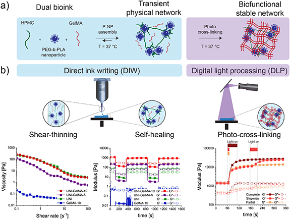
Figure 2. Design and mechanical properties of the dual bioinks. (a) Schematic overview of the dual bioink formulation composed of HPMC, PEG-b-PLA NPs, and GelMA. Once the three components were mixed together, PNP interactions formed a transient physical network at 37 °C. The incorporation of GelMA allowed for further stabilization via photo-cross-linking to tune the mechanical properties of the construct. (b) Rheological characterization of the ink formulations at 37 °C. Left: shear rate ramp (dγ/dt = 0.1–100 s−1) for GelMA-10, UNI, UNI–GelMA-5, and UNI–GelMA-10. The UNI formulations with and without GelMA demonstrated a decrease in viscosity with increasing shear rate (shear-thinning). Middle: step strain measurements for GelMA-10, UNI, UNI–GelMA-5, and UNI–GelMA-10 with alternating intervals at low (γ = 0.3%, ω = 10 rad s−1) and high shear strain amplitude (γ = 100% or 1000% for UNI–GelMA or UNI respectively, ω = 10 rad s−1). The UNI formulations exhibited rapid and reproducible recovery of solid-like properties (G' > G''; self-healing). Right: dynamic oscillatory time sweep measurements (γ = 0.3%, ω = 10 rad s−1) of UNI–GelMA-10 to characterize cross-linking kinetics upon irradiation (λ = 405 nm, I = 10 mW cm−2). Three different time intervals of light exposure were investigated: (1) complete cross-linking was obtained through photopolymerization (light on) for 60 s; (2) partial cross-linking was obtained through photopolymerization (light on) for 10 s; and (3) stepwise cross-linking was obtained through a first interval of photopolymerization (light on) for 10 s, an interval of 120 s without photopolymerization (light off), and a further photopolymerization (light on) interval for 50 s.
Download figure:
Standard image High-resolution imageIn order to use the UNI–GelMA inks for extrusion-based printing, we investigated the shear-thinning and self-healing properties of the dual bioinks. Similar shear-thinning properties were observed for the different formulations (nUNI = 0.31 ± 0.01, nUNI–GelMA-5 = 0.35 ± 0.09, and nUNI–GelMA-10 = 0.18 ± 0.07; figure 2(b)). In addition, each of the dual bioinks exhibited rapid self-healing during step strain measurements. Thus, the combination of the UNI platform with GelMA provided dual bioinks with shear-thinning and self-healing properties suitable for DIW, which were not observed for GelMA alone at 37 °C.
In addition to having rheological properties for DIW, we also demonstrated the ability for the dual bioinks to undergo secondary photo-cross-linking to replicate the process of photopatterning with DLP. We investigated the cross-linking kinetics of UNI–GelMA-5 and UNI–GelMA-10 upon exposure to visible light (λ = 405 nm, I = 10 mW cm−2) for varying time intervals. Photopolymerization of both dual bioinks induced a rapid increase in mechanical properties, which then slowed with increasing exposure time (figure 2(b); figure S6). Based on the kinetics of the photopolymerization, we defined exposure times for partial cross-linking, tpartial = 10 s, and complete cross-linking, tcomplete = 30 s or 60 s for UNI–GelMA-5 and UNI–GelMA-10, respectively. The storage moduli of both formulations increased after partial cross-linking (G'UNI-GelMA-5,partial = 3.2 ± 0.4 kPa and G'UNI-GelMA-10,partial = 15.6 ± 3.6 kPa). The moduli continued increasing with additional light exposure until the time of complete cross-linking, beyond which no relevant change in the modulus was observed. We also applied a stepwise photopolymerization, in which the samples were partially cross-linked (tpartial = 10 s) and after 2 min of equilibration (light turned off), the cross-linking reaction was continued for an additional 20 s or 50 s, in order to reach complete cross-linking of UNI–GelMA-5 (tstepwise = 10 s + 20 s) and UNI–GelMA-10 (tstepwise = 10 s + 50 s), respectively. No differences in mechanical properties were observed between stepwise and complete cross-linking (G'UNI-GelMA-5,stepwise = 4.5 ± 0.3 kPa, G'UNI-GelMA-5,complete = 4.4 ± 1.0 kPa, and G'UNI-GelMA-10,stepwise = 29.1 ± 7.3 kPa, G'UNI-GelMA-10,complete = 26.8 ± 3.2 kPa).
Overall, these results demonstrated that light exposure could be used to tailor the mechanical properties of the dual bioinks and that the sequence of cross-linking did not affect the final modulus of the material. In addition, a tunable tpartial could be used to modulate the local mechanical properties in the material by varying exposure time and a short tcomplete was beneficial to reduce the total fabrication time for our multitechnology approach.
3.3. Fabrication of hierarchical biomaterials via photopatterning-enhanced DIW
In order to fabricate 3D hierarchical biomaterials with defined properties at both micro- and macro- scale, we coupled a pneumatic-driven 3D printer for DIW with a digital micromirror device for DLP (figure S7). Using this approach, we printed different biomaterial inks sequentially to control their spatial organization (figure 3(a)). We then used DLP to control the micro-scale mechanics of the construct by projecting photopatterns onto the printed material. We manufactured a stainless steel plate adapter to ensure alignment and orientation of the printed construct during transfer from the 3D printer to the DLP (figure S8).
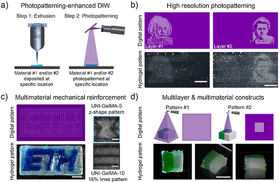
Figure 3. Hierarchical biomaterials via photopatterning-enhanced DIW. (a) Schematic representation of the multitechnology printing approach. The 1st step consisted of depositing (DIW) one or multiple layers of the scaffold by controlling the composition and the spatial location of different biomaterial inks. In the 2nd step, the layer was photopolymerized (DLP; λ = 405 nm, I = 10 mW cm−2) with defined patterns and time of cross-linking. This process was repeated layer by layer to fabricate the 3D construct. (b) A bilayer scaffold was fabricated with distinct grayscale features via photopolymerization of separate locations. The bottom layer was photopolymerized with a projected picture of Albert Einstein, whereas the upper layer was photopolymerized with a picture of Marie Skłodowska Curie. Scale bars, 5 mm. (c) A single layer scaffold was fabricated with two biomaterial ink formulations and two different patterns. In a sequential manner, UNI–GelMA-5 (blue) was printed in the shape of the inner ETH Zurich logo. UNI–GelMA-10 (clear) was printed as a surrounding rectangle. After DIW, a simultaneous photopolymerization step was performed. A z-shape design was patterned within the ETH logo and a 16% line design was patterned with the surrounding rectangle. Scale bars, 5 mm (scaffold) and 500 µm (patterns). (d) A 3D multimaterial scaffold was fabricated by sequentially depositing two layers with two biomaterial inks (UNI–GelMA-10 with and without green color) at different locations. After printing two layers, the multimaterial construct was photopolymerized (uniform cross-linking for 2 s followed by patterning an internal square 4 × 4 mm for 50 s). The process was repeated, and a final 3D scaffold with ten layers was fabricated. Scale bar, 5 mm.
Download figure:
Standard image High-resolution imageThe integration of DIW and DLP within a single print technology through the design of dual bioinks enabled multiple fabrication opportunities, including grayscale patterning in distinct print layers, differential mechanical reinforcement within distinct regions of a printed construct, as well as multimaterial objects with multilayer mechanical reinforcement. To demonstrate grayscale patterning, we printed a bilayer construct. After printing the first layer, the material was patterned via DLP. An initial uniform exposure (t = 10 s, λ = 405 nm, I = 10 mW cm−2) partially solidified the whole layer. Thereafter, a grayscale image of Albert Einstein was projected on the left side of the printed layer (t = 50 s, λ = 405 nm, I = 10 mW cm−2; figure 3(b)). Following a similar approach, a second layer was printed and a grayscale image of Marie Skłodowska Curie was patterned on the right side of the construct.
To provide differential mechanical reinforcement, a multimaterial scaffold was printed with two dual bioink formulations (UNI–GelMA-5, and blue; UNI–GelMA-10, clear). Each ink was loaded into a separate heated cartridges (37 °C) and mounted with straight nozzles (22 G; Ø = 410 µm). The ETH Zurich logo was printed in UNI–GelMA-5, and surrounded by printed rectangular frame of UNI–GelMA-10 (figure 3(c)). After DIW, the multimaterial construct was reinforced via DLP. An initial uniform exposure (t = 10 s, λ = 405 nm, I = 10 mW cm−2) partially solidified the whole construct. In a 2nd step, distinct patterns (parallel lines for the surrounding frame; z-shaped design for the ETH logo) were simultaneously projected onto the construct (t = 50 s, λ = 405 nm, I = 10 mW cm−2). To confirm polymethacrylate cross-linking at the site of photopatterning acryloxyethyl thiocarbamoyl rhodamine B was used for visualization of patterns crosslinked for tstepwise (figure S10). With this approach, it was possible to control the spatial deposition of different biomaterial inks and to pattern specific features in distinct regions of the final construct.
To control structure and composition at both micro- and macro-scale, a multimaterial 3D object (length = 7 mm, width = 7 mm, and ten layers of 0.35 mm thickness) was printed with patterned light-exposure to form a reinforced cuboid within the multimaterial construct. UNI–GelMA-10 (green and clear) was used for both inks. The inks were loaded into separate heated cartridges (37 °C) and mounted with straight nozzles (22 G; Ø = 410 µm). First, the materials were deposited sequentially to form the 1st two layers. The printed layers were then treated with a stepwise photopatterning step; the surface was homogeneously cross-linked (t = 2 s, λ = 405 nm, I = 10 mW cm−2) and then an internal square geometry (length = 4 mm; width = 4 mm) was patterned (t = 50 s, λ = 405 nm, I = 10 mW cm−2) in the center of the scaffold. This process was repeated to form the 3D construct. Despite the scattering of the thick construct, the internal 3D cuboid pattern was visible at the end of the process (figure 3(d)).
Overall, our printing approach that combined DIW and DLP with dual bioinks provided a simple and user-friendly strategy to fabricate multimaterial scaffolds with controlled properties at both micro- and macro-scale. DIW enabled the controlled deposition of multiple materials with a resolution of ∼410 µm, which was determined by the nozzle diameter. DLP provided tunable control over the mechanical properties and reinforcement of the constructs. The pattern design, grayscale intensity, and time of exposure dictated the local degree of GelMA cross-linking and the spatial resolution (∼100 µm, figure S9). A further advantage of DLP photopatterning is that grayscale images can be exploited to simultaneously generate structures having different cross-linking degrees without the need for stepwise photopolymerization, accelerating fabrication.
3.4. Photopatterning-enhanced DIW for mechanical reinforcement of 3D-printed constructs
Another useful application of photopatterning-enhanced DIW is spatially controlled mechanical reinforcement of 3D constructs. To achieve this, the freedom of design provided by DLP was combined with the phototunable mechanical properties of the dual bioinks to fabricate composite scaffolds with high resolution mechanical reinforcement (figure 4(a)). We exploited the difference in modulus for UNI–GelMA-10 after two distinct intervals of photopolymerization. Partially cross-linked regions of the scaffold were labeled as matrix (tpartial = 10 s) and fully cross-linked regions were labeled as reinforcement (tcomplete = 60 s). Initially, bulk materials were cross-linked and the mechanical properties of the constructs were characterized by tensile testing after equilibration. The elastic modulus increased with the time of cross-linking (Epartial = 6.4 ± 2.9 kPa and Ecomplete = 28.9 ± 4.4 kPa) with similar Poisson's ratios (vpartial = 0.4 ± 0.1 and vcomplete = 0.3 ± 0.1). Composite structures were fabricated in a sequential approach—in an initial step the matrix was cross-linked homogeneously (tpartial = 10 s), and in a 2nd step the reinforcement structures were patterned (t = 50 s). We produced constructs with different designs and volume fractions of reinforcement (lines, 16% and 33%, and z-shaped; figure 4(a)).
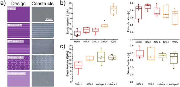
Figure 4. Tensile properties of mechanically reinforced UNI–GelMA-10 constructs. (a) Digital design of reinforcement patterns (left) and resulting patterned structures in 3D hydrogel scaffolds. Scale bar, 2 mm. (b) Elastic moduli (left) and Poisson's ratio (right) measured by uniaxial tensile tests of scaffolds with increasing volume fraction of the patterned reinforcement (16% //: 16% line reinforced scaffold tested parallel to the line orientation; 33% ⊥: 33% line reinforced scaffold tested perpendicular to the line orientation; and 33% //: 33% line reinforced tested parallel to the line orientation). The scaffold fabricated with 33% line reinforcement tested parallel to the line orientation resulted in a statistically significant increase (*, p < 0.05) in elastic modulus as compared with the non-patterned matrix. (c) Elastic moduli (left) and Poisson's ratio (right) measured by uniaxial tensile tests of scaffolds with different designs of patterned reinforcement (33% ⊥: 33% line reinforced scaffold tested perpendicular to the line orientation; 33% //: 33% line reinforced tested parallel to the line orientation, z-shape ⊥: z-shape reinforced scaffold tested perpendicular to the z-shape; z-shape //: z-shape reinforced scaffold tested parallel to the z-shape).
Download figure:
Standard image High-resolution imageTo determine the efficiency of reinforcement, the elastic moduli of the reinforced composites (16% and 33% lines) were compared with standard composite theory [56]. When the reinforcement was photopatterned as lines parallel to the direction of applied stress, the longitudinal strain in the matrix and fiber reinforcement should be equal, whereas the reinforcement structures should experience larger stress than the matrix due to the larger elastic modulus (Ecomplete > Epartial). In this case, the upper bound on the elastic modulus of the composite can be described by the rule of mixtures (E// = Er ϕ + Em(1 − ϕ)) for a perfectly reinforced composite, where ϕ denotes the volume fraction of reinforcement and the subscripts r and m denote reinforcement and matrix, respectively [56, 57]. The measured elastic moduli of the patterned constructs (E16% reinforcement //,Exp = 9.2 ± 2.8 kPa and E33% reinforcement //,Exp = 12.9 ± 1.2 kPa) were comparable to the upper bound estimated based on the rule of mixtures (E16% reinforcement //,Model = 10.1 kPa and E33% reinforcement //,Model = 13.8 kPa) (figure 4(b)). The scaffold fabricated with 33% line reinforcement tested parallel to the line orientation resulted in a statistically significant increase (p < 0.05) in elastic modulus as compared with the non-patterned matrix. In contrast, minimum reinforcement should occur when the tensile load is applied perpendicular to the orientation of the reinforcement. In this case, the load should be distributed uniformly between matrix and reinforcement structures, and the resulting lower bound on the elastic modulus of the composite can be estimated using the transverse rule of mixtures (E⊥ = Er Em/(Er(1 − ϕ) + Em ϕ)). Again, observed elastic moduli followed the rule of mixtures (E33% reinforcement ⊥,Exp = 8.8 ± 2.8 kPa vs E33% reinforcement ⊥,Model = 8.6 kPa; figure 4(b)). In all cases, the Poisson's ratio was not affected by the reinforcement structure used.
DLP enables arbitrary reinforcement patterns beyond simple parallel reinforcement. We also prepared constructs with a z-shaped reinforcement pattern. In contrast to the line reinforcement, composite structures reinforced with z-shaped patterns exhibited similar elastic moduli (Ez-shape reinforcement // = 13.5 ± 1.3 kPa and Ez-shape reinforcement ⊥ = 13.9 ± 3.9 kPa; figure 4(c)) and Poisson's ratios independent of the orientation of the tensile load. Thus, pattern design was used to tailor the extent of anisotropy in the mechanical reinforcement. Overall, we demonstrated that the spatiotemporal control provided by DLP enables facile and tunable reinforcement of 3D constructs. In the future, z-shape reinforcements could be used to fabricate auxetic materials with negative Poisson's ratio; however, a larger difference in elastic moduli between the matrix and the reinforcements would be necessary [58].
3.5. Cell viability and morphology in dual printed constructs
Finally, we demonstrated that cells remained viable following photopatterning-enhanced DIW toward applying this multitechnology printing approach for biofabrication. We encapsulated hMSCs in both UNI–GelMA-5 and UNI–GelMA-10 bioinks and produced cell-laden 3D-printed constructs. In case of UNI–GelMA-5, all samples, except the non-printed controls, were printed as a bilayer rectangular shape using DIW. In a 2nd step, the scaffolds were photo-cross-linked via DLP. Different time intervals (tpartial = 10 s, tcomplete = 30 s, and tstepwise = 10 + 20 s) and pattern designs (uniform or 16% fiber reinforcement) were used to photopattern (λ = 405 nm, I = 10 mW cm−2) the 3D-printed constructs. In addition, as a representative biological structure, we 3D printed a meniscus using UNI–GelMA-10 (figure 5(a)). The meniscus constructs were printed and photopatterned with mechanical reinforcement inspired by the natural arrangement of the collagen fibrils (circumferential and radial alignment) [59–61]. The extruded filaments were deposited in a circumferential orientation and then followed by photopatterning. Different time intervals (tpartial = 10 s, tcomplete = 60 s, and tstepwise = 10 + 50 s) and pattern designs (uniform or radial mechanical reinforcement lines) were used to photopattern (λ = 405 nm, I = 10 mW cm−2) the 3D-printed constructs. All samples, UNI–GelMA-5 and UNI–GelMA-10, showed similar cell viability compared to non-printed control scaffolds at days 0, 1, 2, and 5 (figures S11–S14).

Figure 5. Bioprinting via photopatterning-enhanced DIW. UNI–GelMA-10 was used as a dual bioink to encapsulate hMSCs (2.0 × 10⁶ cells mL−1) within bioprinted meniscus. (a) Left: representative anatomical model of meniscus tissue. Center: the 3D model was designed using CAD software. The meniscus constructs were printed and photopatterned inspired by the natural arrangement of collagen fibrils. The extruded filaments were deposited following a circumferential orientation and the respective radial reinforcement lines were photopolymerized using different degrees of cross-linking of UNI–GelMA-10 (λ = 405 nm, I = 10 mW cm−2): (1) partial cross-linking (10 s) without reinforcement patterns; (2) complete cross-linking (60 s) without reinforcement patterns, and (3) stepwise cross-linking (10 s uniform cross-linking, followed by 50 s cross-linking of radial mechanical reinforcement lines). Right: the final 3D-printed meniscus construct (scale bar, 5 mm) with ∼100 µm thick radial reinforcements (scale bar, 500 µm). For comparison, non-bioprinted control scaffolds were photopolymerized with two strategies (either partial crosslinking for 10 s or complete crosslinking for 60 s) without undergoing the printing process. (b) Representative images of hMSCs in bioprinted and non-bioprinted control scaffolds revealed similar spreading at day 0 and day 5 after biofabrication. Actin cytoskeleton was labeled with Alexa Fluor488 Phalloidin (green) and nuclei were labeled with DAPI (blue). Scale bar, 50 µm.
Download figure:
Standard image High-resolution image
We also investigated if local mechanical properties in the different constructs or within the patterned regions had an effect on cell-material interaction. Similar cell spreading was observed in both non-printed control and bioprinted samples after 5 d in culture (figures 5 and S15). Moreover, the spatial control over the cross-linking via photopatterning and the slow but constant release of HPMC from the scaffold (figure S16) did not significantly influence cell morphology. Overall, these results demonstrated the cytocompatibility of our approach to fabricate hierarchical composite biomaterials. In the future, this feature could be useful to better mimic tissue anisotropy and replicate tissue organization in cell-laden constructs at the micro- and macro-scale.
4. Conclusion
Our approach provided a facile method to fabricate hierarchical biomaterials via photopatterning-enhanced DIW. We combined two common AM technologies—DIW and DLP—that were operated sequentially within dual bioinks to overcome limitations of each individual technology, creating high resolution multimaterial scaffolds. In this manner, the spatial resolution of the mechanics was not limited by the nozzle diameter as higher resolution features were generated via photopatterning. Similarly, material composition was decoupled from a resin, since multiple printheads provided spatial control over the material composition of the structure. This approach was enabled by the formulation of dual bioinks with shear-thinning and self-healing properties for DIW that could be photocured via DLP. To achieve this, we combined a UNI platform based on PNP hydrogels with GelMA. Varying the exposure time produced regions of the construct with different mechanical properties. This technology enabled the biofabrication of hierarchical hydrogel scaffolds with spatially-defined mechanical reinforcement. Moreover, the photopatterning-assisted DIW approach was compatible with bioprinting of cell-laden inks. Overall, this approach provides a unique approach to tailor the complex architecture and mechanical properties of biofabricated constructs.
Acknowledgments
This project was supported by start-up funds from ETH Zurich and the Swiss National Science Foundation under Project No. 200021_184697. A W was supported by the Swiss National Science Foundation under Grant No. 179012. The authors acknowledge Professor Dr Ivan Martin at the University Hospital Basel for providing us with hMSCs, Lisa Krattiger for support in cell culture experiments, the Particle Technology Laboratory (Professor Dr Sotiris E Pratsinis, ETH Zurich) and the Experimental Continuum Mechanics Laboratory (Professor Dr Edoardo Mazza, ETH Zurich) for generous access to their facilities, and Peter Feusi for manufacturing the plate adapter for the BioX and DLP printer.
Data availability statement
The data that support the findings of this study are available upon reasonable request from the authors.