

Abstract
Despite the usefulness of hydrogels for cell-based bioprinting, the fragility of their resulting constructs has hindered their practical applications in tissue engineering research. Here, we suggest a hybrid integration method based on cell-hydrogel bioprinting that includes alternate layering of flexible nanofiber (NF) sheets. Because the bioprinting was implemented on a nanofibrous surface, the hydrogel-based materials could be printed with enhanced shape resolution compared to printing on a bare hydrogel. Furthermore, the insertion of NF sheets was effective for alleviating the shrinkage distortion of the hydrogel construct, which is inherently generated during the crosslinking process, thereby enhancing shape fidelity throughout the three-dimensional (3D) architecture. In addition to the structural precision, the NF-embedded constructs improved the mechanical properties in terms of compressive strength, modulus, and resilience limit (up to four-fold enhancement). With structural and mechanical supports, we could 3D fabricate complex constructs, including fully opened internal channels, which provided a favorable perfusion condition for cell growth. We confirmed the enhanced bioactivity of the NF-embedded bioprinted construct via cell culture experiments with 80% enhanced proliferation compared to the monolithic one. The synergistic combination of the two flexible materials, NFs and hydrogels, is expected to have extensive applicability in soft tissue engineering.
Export citation and abstract BibTeX RIS
1. Introduction
Among the variety of biomaterials, hydrogels have served many feasible applications, especially in cell-based soft tissue engineering [1, 2]. Because of their water retention and tissue-like or cell-like softness, they can provide hydrated cell-viable physiological conditions and mechanically compatible environments that simulate native tissues or their extracellular matrix [3, 4]. Taking advantage of these properties, hydrogel materials have recently attracted much attention for applications in three-dimensional (3D) bioprinting as a form of mixture with living cells, which are called bioinks. However, for the implementation of 3D printing of bioinks, the biocompatible softness of hydrogels has frequently acted as a contradictory weakness due to its inherent fragile rigidity, which causes vulnerable shape integrity and poor mechanical durability [5, 6]. Typical approaches to enhance the structural and mechanical fidelity have included increasing the crosslinking density of hydrogels, which could provide stiffer material properties [7–10]. However, highly crosslinked hydrogels have been concerning due to the limitation of cell viability, growth, and mass transfer of nutrients, oxygen, and cell secretions [11]. Ideally, to simultaneously obtain biological compatibility and shaping fidelity, the printing conditions, including the crosslinking extent and other process parameters, should be carefully considered.
Alginate is one of the representative ion-based curing hydrogels and is generally crosslinked by Ca ions in calcium chloride (CaCl2) solution. In a typical bioprinting process using alginate, it has been usually printed as a cell-laden mixture, which is slightly cured by mixing with a diluted CaCl2 solution [12–15]. This is intended to provide a feasible rheology for implementing 3D bioprinted constructs that reduces the possibility of collapse of the hydrogel. However, this method still has limitations for securing the z-directional dimension in bioprinted constructs due to the liquid-like behavior of the printed materials. Furthermore, the mechanically vulnerable printed constructs can hardly sustain the morphological architectures during the process of cell culture and other manipulations for assays or operations. To overcome the fragility of hydrogel-based constructs, hybrid fabrication strategies using stiffer materials have been considered as a promising solution. For instance, mechanically supportive materials, such as polycaprolactone (PCL), have been printed to form frameworks for further in situ printing of cell hydrogels [16–18]. This approach provides a good structural integrity even for realizing patient-specific tissue substitutes. However, the limited flexibility due to the stiff and thick framework struts (hundreds of micrometers in thickness) should be still overcome for practical applications in soft tissue engineering. Many researchers have still suggested a variety of composite models integrating hydrogels and reinforcing support structures [19, 20].
Here, we propose an integrative method to create 3D bioprinted constructs while retaining the robust shape integrity and the inherent softness of the hydrogel material. This was attained by hybrid alternate integration of bioprinted cell-hydrogel layers and flexible electrospun nanofiber (NF) sheets. Electrospinning is one of the most promising techniques for manufacturing nanoscale-diameter fibers in a highly productive way [21]. Since it endows the as-fabricated fibers with a great flexibility based on the ultrathin diameter and extremely high aspect ratio, the electrospun fiber sheets have been extensively used for flexible scaffolds in soft tissue engineering [22]. Regarding the mechanical properties, we employed electrospun nanofibrous sheets to reinforce the bioprinted constructs. The bioprinting process on the sheet was performed with a good shape fidelity to produce complex and refined shapes, such as microchannel-included structures. In addition, the fiber-reinforced architecture enhanced the structural and mechanical properties, which are durable against shrinkage due to postcrosslinking, gel weakening during cell culture, and external compressive stimulation. Using cell culture experiments, we confirmed that the robustness and well-defined geometry of our developed constructs offer a favorable condition for the viability of cells embedded in the constituent hydrogels.
2. Materials and methods
2.1. Preparation and printing of the hydrogel inks
Sodium alginate powders (Sigma Aldrich, USA) were dissolved in a cell culture medium at a concentration of 3% or 5% (w/v). To improve the printability, the viscosity of the alginate solution was increased by using a 1.5 ml of a 1% CaCl2 solution (w/v) in a total of 10 ml of the alginate solution. The printing machine was a customized system that consisted of a three-axis moving table, a plastic syringe equipped with a microneedle, a dispensing syringe pump, and a clean booth surrounding the entire printing system. To understand the process parameters in the developed system, we tested the hydrogel printing of one-dimensional (1D) strands with varying hydrogel concentrations (3% and 5%), syringe movement speeds (1–9 mm s−1), needle diameters (0.3, 0.5, and 0.7 mm), and material feedrates (14, 18, and 22 ml h−1).
2.2. Preparation of the electrospun NF sheets
The NF sheets were fabricated by electrospinning of polycaprolactone (PCL) solutions. The PCL granules (MW of 80 000, Sigma Aldrich, USA) were dissolved in a 75/25 (volume ratio) mixture of methylene chloride and dimethylformamide at a concentration of 14% (w/v). The polymer solution that was loaded in a plastic syringe was infused at a feedrate of 3 ml h−1 and then electrospun through a metal needle with a diameter of 0.25 mm by applying 15 kV to the needle. The distance from the needle to the collector was set at 15 cm. For facile manipulation of the electrospun sheets, which easily collapsed due to their thin geometry, a tentative plastic framework with a square shape (25 × 25 mm2) was placed on the collector, thus producing a single framed NF sheet. After the hybrid printing integration with hydrogels in the following step, the framework could be easily removed by simple manual detachment.
2.3. Hybrid integration of the bioprinted construct with the NF sheets
The as-prepared NF sheets were inserted between the hydrogel layers during the bioprinting process. The hybrid hydrogel constructs involving the NF sheets were fabricated by repeating and alternating the bioprinting with insertion of the NF sheets. For intimate adhesion with the hydrogel layers, both the upper and lower surfaces of the NF sheets were treated by oxygen plasma at 15 W for 1 min before insertion. To assess the influence of the presence of the NF sheets, hydrogel printing tests were performed by depositing 1D strands on bare and NF-covered substrates. PDMS (Polydimethylsiloxane) and the as-printed alginate layer were selected to be the test substrates, which were postulated to be the substrates for printing the initial layer and subsequent layers, respectively. Separately, to further understand the interfacial behavior, the contact angles were measured by laying the droplets of alginate solution and water on both types of substrates.
2.4. Shrinkage and compression tests of the hybrid constructs
To evaluate the shrinkage of the hydrogel constructs, two-dimensional and 3D structures were printed with and without the NF sheets. They were tested by applying 5% CaCl2 solutions for 5 min and then measuring the dimensions of the area and height. For these tests, 3% alginate solutions were printed into square shapes of 20 × 20 mm2 with 1 and 5 layers for the 2D and 3D samples, respectively. The printing parameters included a material feedrate of 20 ml h−1, a syringe movement speed of 6 mm s−1, and a needle diameter of 0.5 mm. Using the same printing parameters, samples for compression tests were prepared by printing 10 layers with and without the insertion of the NF sheets. Both samples were equally treated with 5% CaCl2 solutions for 5 min The compression tests were performed using a micromaterial tester (E3000LT, Instron, UK) at a compression rate of 1 mm min−1.
2.5. Cell culture experiments with the hybrid constructs
NIH 3T3 fibroblasts purchased from Korea Cell Line Bank were cultured in Dulbecco's Modified Eagle Medium (DMEM, HyClone, USA) with 10% heat inactivated bovine calf serum (BCS, Gibco, USA) and 1% penicillin-streptomycin (Gibco) at 37 °C in 5% CO2. For the cell-laden bioprinting process, NIH 3T3 fibroblasts were suspended in 3 ml of cell culture media (DMEM) at a density of 5 × 10⁶ cells ml−1. Then, a total of 10 ml of bioink at an alginate concentration of 5% (w/v) was prepared by mixing the cell suspension with the base alginate solution that included 1.5 ml of the 1% CaCl2 solution. With this bioink, woodpile-shaped structures that had 5 layers were printed in an area of 20 × 20 mm2. The printing paths for the woodpile shape were designed with a line distance of 2.5 mm and orthogonally varied directions (x-axis to y-axis) between the adjacent layers. The printing parameters were the same as for the shrinkage and compression experiments. After the bioprinting, the samples were transferred to a 6-well plate, treated with a 5% CaCl2 solution for 2 min, washed three times with PBS, and then immersed in DMEM culture media.
For the live/dead cell viability assay, bioprinted samples with and without the interstitial NF sheets were incubated in culture media for 7 d in a humidified atmosphere of 5% CO2 in air at 37 °C. The cells were stained on day 1 and 7 using a Live/Dead® Viability/Cytotoxicity Kit (InvitrogenTM, USA). Then, 20 μl of the supplied 2 mM ethidium homodimer (EthD-1) stock solution and 5 μl of the 4 mM calcein AM stock solution were mixed in 10 ml of PBS, and a 2 ml solution was added to each cell-printed scaffold. The cell-printed scaffolds were incubated for 30 min in the live/dead dye solution, and live/dead cells were observed using fluorescence microscopy (EVOS FL Cell Imaging System, Thermo Fisher Scientific, USA). In addition, histological analysis was performed on the two types of bioprinted constructs with and without the NF sheets, which were cultured for 7 d and then fixed in a 4% paraformaldehyde solution. Then, the fixed samples were mounted with an optimal cutting temperature (OCT) compound, frozen, and sectioned into 7 μm thick slices. The sliced samples were stained using hematoxylin and eosin and observed using an optical microscope.
To assess the cell proliferation in the bioprinted constructs, an MTS assay to measure the metabolically active cells was performed with the samples made under three different conditions: (A) samples without the NF sheet but with additional periodic crosslinking (treatment of 5% CaCl2 solution for 2 min every 2 d), (B) samples without the NF sheet and with only an initial crosslinking, and (C) samples with NF sheets and with only an initial crosslinking. For the MTS assay, the CellTiter 96® AQueous One Solution Cell Proliferation Assay Kit (Promega, USA) was used following the manufacturer's instructions. After replacing with 5 ml of fresh growth media, 500 μl of MTS reagent was added to each well plate and incubated for 1 h at 37 °C in 5% CO2. The absorbance was detected at 490 nm with a Microplate Reader (SpectraMax iD3, Molecular Devices).
2.6. Statistical analysis
In the parameter studies of hydrogel printing process, each measurement of line width was performed more than six times to obtain statistically significant results. Due to the relatively small deviation, the experimental results are reported as mean values. In the cell proliferation assay, the mean ± standard deviation values were measured from five different MTS reagents in each sample.
3. Results and discussion
3.1. Hydrogel printing process on the NF sheets
The fundamental procedures for the bioprinting process with hydrogel-based bioinks include extrusion through a nozzle, deposition on a substrate, integration into the 2D or 3D entity, and reinforcement via crosslinking. Figure 1(a) shows the bioprinting system equipped with a syringe pump that dispenses the bioinks with microscale precision. The dispensing module can relatively move in three axes according to the predefined paths. With this system, hybrid integration with the NF sheets was performed as shown in figure 1(b). Basically, the integration cycles of hydrogel bioprinting and NF sheet stacking are repeated to obtain a 3D integrated hybrid construct. The NF sheets were fabricated by a typical electrospinning process and supported by a square-shaped framework for easy manipulation (figure 1(c)). The diameter of the constituent fibers and the thickness of the sheet were an average of approximately 420 nm and 20 μm, respectively. Because of their sufficiently thin geometry, the as-fabricated sheets were so flexible that they could have a great mechanical compliance in accordance with hydrogel materials.
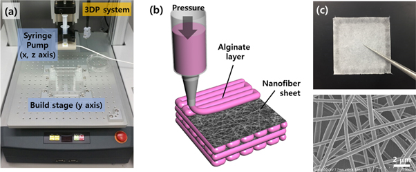
Figure 1. (a) 3D bioprinting system equipped with a microdispensing syringe pump. (b) Schematic illustration of the hybrid bioprinting process to incorporate nanofiber sheets. (c) Photograph and SEM image of the electrospun nanofiber sheet.
Download figure:
Standard image High-resolution imageAs a basic step for hydrogel printing, single-line deposition tests were carried out by varying the process parameters, including the hydrogel concentration, nozzle diameter, material feedrate, and printing speed (figure 2). Overall, because of the precisely controlled movement of the nozzle system, the relationship between line width and printing speed exhibited a consistent tendency of inverse proportion. Beyond a 6 mm s−1 printing speed, the line widths could be realized on the submillimeter scale. Since the alginate precursor solutions at a concentration of 5% provided a sufficient flowability for nozzle dispensing, variations in the concentration and nozzle diameter did not show significant differences for the line widths of the as-printed strands (figures 2(b) and (c)). Because the printing system employed a piston pumping mechanism, the material feedrates were well controlled so that the line widths showed relatively discriminated relationships at the different feedrates (figure 2(d)).

Figure 2. (a) Schematic illustration of the parameter study for the bioprinting process. Relationship between line width of the as-printed alginate strand and the printing speed at other different process parameters, including the (b) solution concentration, (c) nozzle diameter, and (d) material feedrate. All data points for the line widths were found by averaging six values in the measurement.
Download figure:
Standard image High-resolution imageThe parameter experiments shown in figure 2 were performed on a PDMS substrate with a flat surface. We could postulate two different surface conditions of the underlying substrates onto which the as-printed hydrogels were deposited: (i) a flat solid surface of the substrate for printing of the initial layer and (ii) a hydrogel surface of the underlying construct printed in the prior step. In both cases, we performed printing and crosslinking tests to characterize the effects of the nanofibrous surface on the dimensions of the processed hydrogel strands (figure 3). Based on the dimensions of the as-printed strand, the widths from the NF-covered surface (figure 3(b)) appeared to be smaller than those of the bare surface (figure 3(a)) for the overall conditions of the printing speed. This was attributed to the hydrophobic effect of the nanoscale features on the NF-covered substrate, upon which the deposited hydrogel strands were laid in a high contact angle (Wenzel or Cassie-Baxter states) [23]. When the crosslinking agent, CaCl2 (5%), was treated for 5 min, the deposited strands on the bare and NF-covered surfaces were shrunk by an average of 26% and 11%, respectively. The shrinkage rates were calculated by averaging the reduction ratios of the line widths before and after crosslinking for all the printing speed conditions. The smaller shrinkage on the NF surface was also attributed to the nanotopographic features, which were thought to act as binding anchorages with the deposited hydrogels. However, from the second layer printing, the as-printed hydrogel strands were deposited on the surface of the prior integrated hydrogel construct, as shown in figure 3(c). Since the deposited strand was the same material as the underlying construct in contact, its border could not be identified after crosslinking (shown in the inset in figure 3(c)). In contrast, when the as-printed hydrogels were deposited on the NF-covered surface, they still maintained their borders with a moderate average shrinkage of 16% (figure 3(d)).

Figure 3. Printing and crosslinking tests of the hydrogels on different surfaces of (a) bare and (b) nanofiber-covered PDMS substrates and (c) bare and (d) nanofiber-covered alginate base layers. (3% concentration, 6 mm s−1 printing speed, 20 ml h−1 feedrate.) The photographs in the middle row of each figure set are the as-printed and as-crosslinked hydrogel strands. The undermost row shows the relationship between line width and printing speed for each test.
Download figure:
Standard image High-resolution image3.2. Durability against crosslink shrinkage and external compression
To enhance the mechanical and structural robustness, the alginate-based constructs should be further crosslinked by calcium chloride as a postprocess for bioprinting, thus causing them to shrink. Figure 4 shows the results of the shrinkage test using several types of 2D or 3D printed alginate constructs. For constructs printed without the NF sheet, the shrinking rates were 39% and 25% for the single-layer and five-layer constructs, respectively (figures 4(a) and (c)). While the huge amount of shrinkage in the NF-excluded constructs, however, the NF-embedded constructs exhibited less than half the shrinkage rates of 19% and 12% for the single-layer and five-layer constructs, respectively (figures 4(b) and (d)). In addition to 1D printing tests, we also confirmed the effect of the NF mat on the alleviation of shrinkage for the 2D or 3D printed constructs. In view of not only the shrinkage mitigation but also the shape uniformity, the embedding of the NF mats was advantageous for minimizing the unpredictable deformation due to the crosslinking shrinkage. The as-printed constructs without the NF mat had irregular shape changes in terms of the morphological clarity of the edge lines and corners (figures 4(a) and (c)). In comparison, the NF-embedded constructs underwent conformal shrinkages but retained the original morphology (figures 4(b) and (d)).
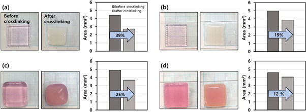
Figure 4. Shrinkage tests of the as-printed alginate constructs of (a), (b) one layer and (c), (d) five layers. Each figure set shows the photographs before/after crosslinking and the histogram of the area change generated from the crosslinking shrinkage. The alginate constructs were integrated (a), (c) without and (b), (d) with NF mats.
Download figure:
Standard image High-resolution imageSince the 3D hydrogel construct is implemented via consecutive integration of layers in the z-axis, the interfacial interactions between the adjacent layers are very important factors with respect to the mechanical robustness and shape fidelity. The hydrogel interfaces were characterized using contact angle tests as shown in figure 5. To further determine the physical spreading during hydrogel printing, we performed an additional set of experiments using hydrogel droplets and water droplets. Similar to the conventional printing process, when the base substrate was bare hydrogel with a hydrophilic interface, it naturally provided a completely wetting interface (figure 5(a)) in which the hydrogel droplet spread with a small contact angle of 41° (figure 5(d)). As expected, the NF-covered surfaces exhibited hydrophobic conditions with high contact angles of 121° and 111° for water and alginate droplets, respectively (figures 5(b) and (e)). Although this hydrophobic surface with the low spreading of hydrogel can control the width of the deposited strand and guarantee the z-axis dimension, it may also cause a negative effect of a weak adhesion between the adjacent layers. To address these contradictory issues, the NF sheets were treated with oxygen plasma (15 W for 1 min) and then placed on the underlying hydrogel substrate. As a result, the water and hydrogel droplets were partially wetted with intermediate contact angels of 37° and 64°, respectively (figures 5(c) and (f)). The surface hydrophilicity, which was modified by the plasma treatment, provided a feasible 3D lamination with moderate deposition of the as-printed hydrogels, which simultaneously retained an appropriate z-axis dimension and layer adhesion.
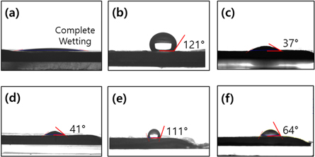
Figure 5. Contact angles of water droplets laid on three different alginate substrates (a) without the NF and covered with (b) nontreated and (c) plasma-treated NF mats. (d)–(f) Contact angles of alginate droplets with the substrates in the same order of (a)–(c), respectively.
Download figure:
Standard image High-resolution imageThe NF sheets were composed of PCL, which is one of the representative FDA-approved polymers. Owing to its rubbery behavior over the extremely low glass transition temperature (−60 °C), the PCL NF sheet was expected to be used for a flexible and reinforcing interstitial layer in the hydrogel-printed construct. Because of the intimate adhesion between the hydrogel and plasma-treated NF mat, we successfully fabricated a ten-layer construct embedded with NF mats in every interstitial layer without any delamination or structural defects, as shown in the leftmost area of figure 6(a). Furthermore, we expected an improvement in the compressive property due to compositing with the NF mats. First, to investigate the effect of NF compositing on the resilience of the performance, we performed compression tests with several different amounts of strain on two different samples of the 3D printed constructs with and without the NF mats. Figures 6(a) and (b) show the results of the compression tests in which the two samples were loaded by a compression of 40% strain and then released. The NF-embedded construct showed nearly full recovery with respect to the height dimension (figure 6(a)), whereas the monolithic alginate construct was compressed down in an irreversible way with failure (figure 6(b)). As shown in the top-view images (the rightmost images), several deep cracks were found on the edge of the monolithic construct, whereas the NF-embedded construct sustained its original circular shape. From some additional compression tests of the varied strain at approximately 40% with a step of 5%, we found a limit of compression strain at failure for each of the two samples. The limit strain values, within which the constructs did not fail and elastically recovered, were 45% and 30% for the NF-embedded and monolithic samples, respectively.
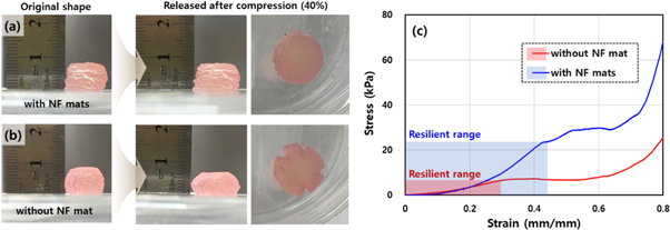
Figure 6. Results of the resilience tests against a compression (40% strain) using 3D printed samples of 10 layers integrated (a) with and (b) without the NF mats. The leftmost images in (a) and (b) show the original shapes of the samples. The right two images are the lateral and top-view photographs of the samples after release of the compression. (c) Stress–strain curves of the two samples of (a) and (b) under continuously increasing compression. The shaded areas indicate the resilient ranges for the samples against compression.
Download figure:
Standard image High-resolution imageThese sections that show elastic behaviors are also observed in the stress–strain curves shown in figure 6(c). The characteristic point starts with a plateau section and is coincident with the limit strain of elasticity for each sample. For the case of cartilage, which a representative tissue that is involved in various compressive environments, several studies based on finite element simulations have suggested that maximum strains exceed 40% (even up to 80%) in the knee cartilage and menisci [24–26]. In this regard, the resilient capability improved by embedment of the NF mats was retained over a 40% strain and provides a meaningful advantage for the design and manufacture of artificial cartilage via hydrogel-based bioprinting. Additionally, in terms of the mechanical stiffness, hybrid integration with NF mats can modulate the properties of the entire construct by increasing the elastic modulus. Based on the stress–strain curves in figure 6(c), the compressive tangential moduli of the NF-embedded and monolithic constructs were measured to be 88.9 kPa and 22.8 kPa at 30% strain, respectively. This result agreed with previous works that showed improved moduli of fiber-reinforced hydrogels [27]. In particular, the value for the NF-embedded sample is comparable with those of other previous experimental results of the moduli of superficial cartilage [28]. Considering the range of moduli for soft tissues, which is from several kPa to MPa [29], we will further study the mechanical compatibility of biomimicking stiffness, which is expected to be attained by varying the inclusion of an NF mat quantitatively or morphologically.
3.3. 3D integrated bioconstruct with enhanced cell viability
Figure 7 shows the importance of the internal architecture for mass transfer with respect to optimal perfusion conditions for cell culture. As is well known, a fully opened porous architecture is considered to be a crucial factor for ideal tissue engineering scaffolds [30, 31]. The open-pore network has to play the role of physical route for mass transfer inside or outside the 3D construct, including ingrowth of cells, supply of nutrients and oxygen, and removal of cell secretions. A woodpile structure, which is composed of alternately layered strand arrays, is one of the ideal architectures that satisfies this requirement; thus, it has been employed for the typical design of 3D printed scaffolds. To secure open pore networks, the strand array in a woodpile structure is typically configured with some spacing between the strands. However, when we printed the alginate solutions over the prior printed strand array, they sagged down to the lower spacing between the underlying strands due to their liquid-like behavior, as shown in figure 7(a). In this case, there was no open space in the lateral directions. In contrast, when the NF sheets were inserted before the hydrogel printing process, they structurally supported it and kept the as-printed strands from sagging or collapsing. As a result, the fully opened channels successfully formed, as shown in figure 7(b). This was expected to guarantee the open perfusion condition both inside and outside the entire structure in the lateral direction. Electrospun NF mats usually have a high porous morphology, providing a sound permeability through the mat [32]. This permeable property of the NF mat, which was embedded in every interstitial layer in our developed construct, was expected to also guarantee vertical transferability. Therefore, the hybrid integrated construct has the capability of omnidirectional mass transfer for cell culture, as shown in figure 7(c).
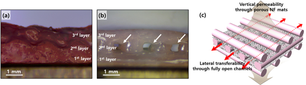
Figure 7. Lateral view images of the three-layer printed alginate constructs (a) without and (b) with the NF mats. The arrows in (b) indicate open channel structures for lateral mass transfer. (c) Schematic illustration of a woodpile structure capable of omnidirectional mass transfer for cell culture.
Download figure:
Standard image High-resolution imageTo practically confirm the advantage of the enhanced open connectivity of the developed construct, we performed cell culture experiments using the samples bioprinted with alginate-based bioinks suspended with living cells. First, the two samples without and with NF mats were compared based on the resulting images from the live/dead assay and sectional histology, which are shown in figure 8. For the live/dead assay, both types of samples had the most cells encapsulated in the bioprinted strands, which remained in a viable state during up to the 7 d culture. As expected, the monolithic printed sample, of which the morphology has been shown in most of other previous works on 3D bioprinting, exhibited a sound viability due to the top pores that allowed the vertical transferability of the culturing substances (figures 8(a) and (b)). This high cell viability could also be observed in the samples integrated with the NF mats (figures 8(d) and (e)). From comparing the viabilities with each other, we excluded the concern about impairment of the vertical mass transfer, which could have been possibly obstructed by the inserted NF mats across the top pores. This implied that the vertical permeation worked well because of the porous characteristics of the NF mats.
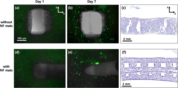
Figure 8. Results of the live/dead assay for (a), (d) the 1 d and (b), (e) the 7 d culture and (c), (f) histological analysis for the 7 d culture. The used samples were prepared by bioprinting (a)–(c) without and (d)–(f) with the NF mats. The fluorescent images are at the same magnification. The fluorescent images and the H&E stained images are a top and a lateral view, respectively.
Download figure:
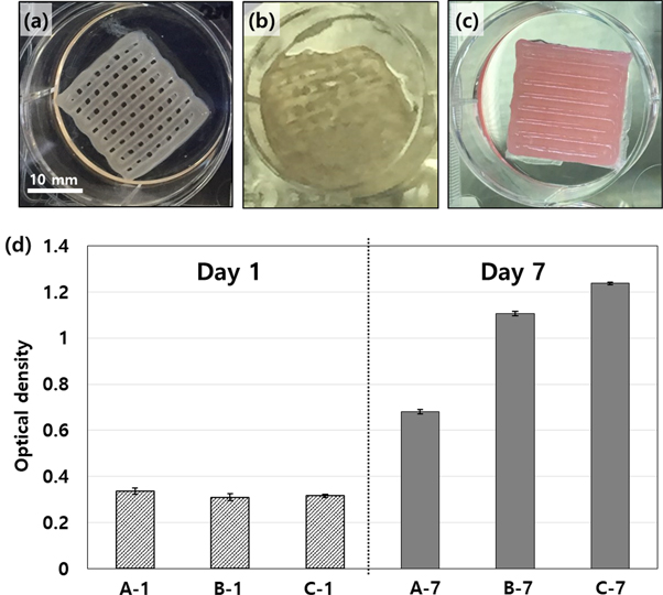
Standard image High-resolution imageSince the NF-supported construct provided omnidirectional transferability (figure 7(c)), the cell growth was expected to be enhanced compared to the typical monolithically printed construct. Figures 8(c) and (f) show the results of the sectional histology after 7 d of cell culture for the monolithic and the NF-embedded bioprinted constructs, respectively. The NF-embedded construct sustained its original woodpile morphology with open pores in the lateral direction (figure 8(f)), whereas the monolithic construct exhibited a collapsed shape without the lateral pore (figure 8(c)). To investigate the effect of the open pore connectivity on the perfusion condition for cell growth, we performed an MTS assay using as-printed samples of three different types, which were (A) samples without the NF sheet but with periodic crosslinking (treatment of 5% CaCl2 solution for 2 min every 2 d), (B) samples without the NF sheet and with only an initial crosslinking, and (C) samples with the NF sheets and with only an initial crosslinking. Figures 9(a)–(c) show the resultant morphologies of the samples after 7 d of culture and fixation. Basically, the used alginate, a type polysaccharide, involves many polymer strands and positively charged sodium ions in the liquid solution. Thus, the dissociated alginate strands are easily bound by doubly charged calcium ions, which are typically provided by calcium chloride solution. All samples were equally crosslinked by the calcium chloride solutions right after completion of the printing process. However, for the monolithic printed constructs, performing only initial crosslinking was not sufficient for retaining the original morphology of the as-printed constructs due to the weakening of the gel during cell culture. As shown in figure 9(b), the cultured structure appeared to be brittle and partially collapsed after the washing and fixing processes. Fedorovich et al solved the weakening issue of alginate printing by performing additional crosslinking during the cell culture process [33]. Thus, we added the type A sample, which was treated with three more crosslinking processes during incubation. Unlike the type B (only initial crosslinking) sample, the type A sample exhibited a well preserved morphology, as shown in figure 9(a). However, the NF-embedded sample (type C) also exhibited an intact morphology despite the single initial crosslinking as in the case of type B (figure 9(c)). This intactness was attributed to the shape endurance that was reinforced by the NF mats. Furthermore, because the crosslinking agent could easily infiltrate into the lateral pore channel supported by the NF mat, only the single crosslinking could provide a more sufficient gelation compared with the samples without the lateral pores.
Figure 9. Photographs of the fixed samples after 7 d of incubation under different conditions: (a) the monolithic sample with periodic crosslinking (treatment of CaCl2 solution every 2 d) (type A), (b) the monolithic sample with only initial crosslinking (type B), and (c) the NF-integrated sample with only initial crosslinking (type C). (d) Results of the MTS assay at day 1 and 7 using the three different sample types.
Download figure:
Standard image High-resolution image
Figure 9(d) shows the MTS assay results for type A, B and C at day 1 and 7 of incubation. At day 1, all samples (A-1, B-1, and C-1) exhibited similar amounts of the included cells. However, at day 7, the cell proliferation in the type A sample (A-7) was significantly inferior to that of type B (B-7). This implies that further reinforced crosslinking (performed for type A) produced unfavorable conditions for the growing cells. As is known, the extent of crosslinking should be carefully considered to achieve both shape fidelity and cytocompatibility [2, 7]. Basically, with a higher crosslink density, 3D bioprinting can be performed for better shape fidelity but for poorer cytocompatibility. Thus, the NF-supported construct under the type C conditions is a great alternative to avoid compromising the extent of crosslinking. Evidently, cell proliferation in type C at day 7 produced the highest growth rate (C-7 in figure 9(d)) among the samples. The NF-embedded construct showed 1.8-fold increase in the proliferation rate compared to the monolithic one without NF. This implies the omnidirectional transferability supported by the NF mats provides a favorable perfusion condition inside and outside the overall cell-hydrogel construct. Combined with the results of the shape fidelity (figures 8(f) and 9(c)) and cytocompatibility (figure 9(d)), the architecture that has integration of the NF mats increases the formability and feasibility of the 3D bioprinting technique.
4. Conclusions
The crucial factors for the 3D bioprinting technique are based on the methodology that deals with liquid-phase hydrogels. In this study, we suggested an integrative printing method to formulate a 3D hybrid construct with alternately layered hydrogels and NF mats. Using a developed printing system, we performed a comprehensive study of various process parameters that affect the deposition of the as-printed materials. Then, when the NF mats were underlaid in the printing process, we further investigated the influence of the inserted NF mats on the printing precision. The NF mats with a moderate surface wettability and that were treated with oxygen plasma not only enhanced the printing resolution but also played a role in anchoring the as-printed hydrogel layer together. Thus, compared with the monolithic-printed construct, the NF-embedded construct exhibited an improved durability against crosslink shrinkage, a wider range of resilient recovery, and a higher compressive strength and modulus. By exploiting the structural and mechanical robustness, we fabricated a bioprinted woodpile structure with omnidirectional transferability. Using cellular experiments, including a viability assay, sectional histology, and an MTS test, the developed construct was confirmed in terms of its enhanced bioactivity, which was due to the fully opened pore network. Together with its enhanced functionalities, the hybrid 3D printed construct that was supported with the NF mats has the potential to be used as artificial tissues that have biomimicking mechanical and biological characteristics in the field of soft tissue engineering.
Acknowledgments
This work was supported by the Industrial Fundamental Technology Development Program funded by the Ministry of Trade, Industry and Energy (MOTIE) of Korea (10051680, Development of high strength and environmental friendly polymer for 3D printing) and a KITECH (Korea Institute of Industrial Technology) internal project.