

Abstract
Overcoming the problem of vascularization remains the main challenge in the field of tissue engineering. As three-dimensional (3D) bioprinting is the rising technique for the fabrication of large tissue constructs, small prevascularized building blocks were generated that can be incorporated throughout a printed construct, answering the need for a microvasculature within the small micron range (<10 μm). Uniform spheroids with an ideal geometry and diameter for bioprinting were formed, using a high-throughput non-adhesive agarose microwell system. Since monoculture spheroids of endothelial cells were unable to remain stable, coculture spheroids combining endothelial cells with fibroblasts and/or adipose tissue derived mesenchymal stem cells (ADSC) as supporting cells, were created. When applying the favorable coculture ratio, viable spheroids were obtained and endothelial cells spontaneously formed a capillary-like network and lumina, as shown by immunohistochemistry and transmission electron microscopy. Especially the presence of ADSC led to a higher vascularization and extracellular matrix production of the microtissue. Moreover, spheroids were able to assemble at random in suspension and in a hydrogel, creating a macrotissue. During at random assembly, cells reorganized, creating a branched capillary-network throughout the entire fused construct by inoculating with capillaries of adjacent spheroids. Combining the advantage of this natural capacity of microtissues to self-assemble and the controlled organization by bioprinting technologies, these prevascularized spheroids can be useful as building blocks for the engineering of large vascularized 3D tissues.
Export citation and abstract BibTeX RIS
Introduction
Tissue engineered constructs find several applications, as in vitro models for injury, disease, drug screening, or in regenerative medicine to repair, regenerate or replace dysfunctional human tissues or organs. Currently, progress is mainly made in the engineering of thin, avascular tissues, characterized by a low metabolism, i.e. skin and cartilage [1, 2]. In contrast, the engineering of thick three-dimensional (3D) tissues is more challenging due to the limits of diffusion (100–200 μm) [3, 4]. Especially cells situated in the core of a large engineered construct, lack sufficient supply of nutrients and oxygen, and are unable to dispose metabolic products (e.g. CO2), causing poor viability of the center [5, 6]. The main challenge to overcome is the establishment of an extended vasculature throughout the entire engineered tissue for long term survival in vivo [7]. Therefore, a complete vascular tree needs to be embedded, ranging from macrovessels to even capillaries, especially since the exchange of nutrients and other molecules between blood and tissue occurs in the microvasculature [8]. A vascular network can develop through two different processes: vessels can be formed de novo, by assembly of endothelial precursor cells (vasculogenesis) [9], or new vessels can arise from existing microvessels through intusseception or endothelial sprouting (angiogenesis) [10, 11]. Formation, stabilization and maturation of capillary tubes and larger blood vessels are stimulated through interactions of endothelial cells with fibroblasts and mural cells, such as smooth muscle cells and pericytes [12–14]. However, the minimal estimated growth rate of microvessels during angiogenesis is only 5 μm h−1, already leading to manifestation of cell death during the initial phase after implantation of a tissue engineered scaffold or construct [15, 16]. Considering that inosculation of already established microvessels with host vasculature is faster than angiogenesis, it is interesting to create a prevascularized construct in vitro [17, 18]. To generate a fully vascularized tissue construct containing a milimeter- to micron-sized vessel network, two enabling disciplines, micro-engineering and developmental biology, need to be combined. Larger vessels can for example be created by incorporating printed channels composed of sacrificial bioinks, e.g. pluronic F127, whether or not loaded with endothelial cells [19]. Microvasculature of the small micron range (<10 μm), challenging due to the limited resolution of bioprinting techniques, can be formed using a cell-driven self-assembly approach. To overcome the limits of classic tissue engineering, modular strategies have been developed, where tissue constructs are built from the bottom-up, starting from spheroids or microtissues with a tissue specific microarchitecture and extracellular matrix (ECM) as building blocks [20, 21]. This developmental biology inspired strategy is based on cell sorting and (micro)tissue fusion. The organization of cells into a spheroid, or the fusion of spheroids into a macrotissue, is explained by the differential adhesion hypothesis (DAH). The DAH states that multicellular tissues, with surface tensions dependent on their cadherin expression, behave like liquids. Microtissues, consisting of motile cells, will rearrange and merge to maximize their adhesive bonds and minimize their free energy [22, 23]. Spheroid properties and cell density depend on their cellular composition and the use of one (monoculture) or more (coculture) cell types [24]. For the creation of vascularized spheroids, endothelial cells can be cocultured with other cell types as supporting cells, e.g. fibroblasts or mesenchymal stem cells, as they promote angiogenesis by secreting pro-angiogenic factors [25] and support endothelial cell migration, viability and capillary tube formation [20, 26].
These spheroids can be directly assembled in a highly controllable manner by 3D bioprinting [27]. Therefore microtissues need to be formed by a scalable technology that produces large quantities of standardized spheroids with comparable shape and size for continuous dispensing [28]. Till date, the generation of vascularized spheroids is limited to large spheroids with a diameter (>300 μm) non-compatible for bioprinting [29], or smaller coculture spheroids formed by high maintenance culture methods, e.g. hanging drop culture [30, 31]. Although several high-throughput spheroid culture systems have been developed, as yet these are used for the generation of monoculture spheroids [32] or non-vascularized cocultures [33]. The formation of prevascularized microtissues with predefined, controlled size and a high yield was not reported yet. Above all, these vascularized microtissues will be indispensable building blocks for 3D bioprinting of macrotissues mimicking the histoarchitecture of specific tissues.
The present study aimed to develop (pre)vascularized microtissues, with a diameter compatible with 3D bioprinting, in a high-throughput manner by using a non-adhesive microwell system. Human umbilical vein endothelial cells (HUVEC) were cocultured with human foreskin fibroblasts (HFF) and adipose tissue derived mesenchymal stem cells as supporting cells, at different ratios (HUVEC/HFF, HUVEC/ADSC, HUVEC/HFF/ADSC). The effect of the applied cell ratio and supporting cell types on spheroid and vessel formation was assessed. The ability of the spheroids to assemble at random into a larger macrotissue was also investigated.
Materials and methods
Cell culture
HUVEC (Lonza) were cultured in endothelial growth medium (EGM)-2 composed of endothelial basal medium (EBM-2, Lonza®) supplemented with the EGM-2 SingleQuot kit (Lonza). Human foreskin fibroblasts (HFF, ATCC®) were cultured in Dulbecco's modified eagle medium (DMEM) Glutamax (Life Technologies) supplemented with 15% fetal bovine serum (FBS, Life Technologies), 2 mM L-glutamine (Sigma-Aldrich), 100 mM sodium pyruvate (Life Technologies), 10 U ml−1 penicillin, 10 μg ml−1 streptomycin (Life Technologies). Adipose tissue derived mesenchymal stem cells (ADSC, Cryo-Save, Niel, Belgium) were cultured in DMEM Glutamax supplemented with 10% FBS, 50 U ml−1 penicillin, 50 μg ml−1 streptomycin, as previously described [34]. All cell types were used up to passage 10 and were cultured at 37 °C in a humidified 5% CO2-containing atmosphere.
Agarose microwell fabrication and formation of spheroids
Spheroids were generated by using a non-adherent microwell culture system, as previously described [35, 36]. In brief, a 3% w/v Ultrapure Agarose solution (Life technologies) dissolved in sterile PBS was heated and poured on top of a negative polydimethylsiloxane (PDMS) customized mold with a diameter of 18 mm and a height of 3 mm. One mold contained 2865 pores with a diameter of 200 μm and a depth of 220 μm each. Once solidified at room temperature, the agarose microwell was separated from the mold and placed in a 12 well culture plate. Cells were harvested and 500 μl of the desired cell suspension, containing 7.5 × 10⁵ cells, was seeded onto the microwell, resulting in approximately 262 cells per pore. To evaluate the influence of spheroid diameter on capillary-network formation, more cells, 1.0 × 10⁶ cells, were seeded onto the microwell, resulting in approximately 350 cells per pore. For the formation of monoculture spheroids, the cell suspension contained HUVEC, HFF or ADSC. To create cocultures of HUVEC and supporting cells (HFF, ADSC), two different seeding techniques were tested. In the first technique, premixed solutions of HUVEC/HFF, HUVEC/ADSC or HUVEC/HFF/ADSC were seeded onto the microwells. In the second technique, the supporting cell type (ADSC) was seeded onto the microwell, and HUVEC were added 24 h later. For the coculture spheroids, several ratios (x/y) of the different cell types were compared, with x the HUVEC and y the supporting cell types. Cell ratios used were: 1/1, 1/2, 2/1, 1/5, 5/1, 1/9, 9/1. For the HUVEC/HFF/ADSC spheroids, a ratio of 1/9 for example means 1/4, 5/4, 5 (corresponding to ±26/117/117 cells per pore). Approximately one hour after seeding, cells were lowered into the bottom of the microwells due to gravitational force, and spontaneously assembled into spheroids. For the monoculture spheroids, the used culture medium reflected the medium used for expansion in monolayer. Coculture spheroids were cultured in EGM-2 medium. All spheroids were cultured at 37 °C in a humidified 5% CO2-containing incubator. Medium was refreshed after the first 24 h of culture and afterwards every two days. Aggregation of the cells was evaluated by light microscopy and spheroids were harvested on day 1, 4, 7 and 10.
Fusion of spheroids
To assess spheroid fusion into larger constructs, two different methods were used: fusion in suspension and fusion in a hydrogel.
In the first method, HUVEC/HFF, HUVEC/ADSC and HUVEC/HFF/ADSC spheroids, cultured up to day 1 or day 10, were fused in suspension and fused constructs were compared. Approximately 80 spheroids in 20 μl EGM-2 medium were seeded in U-shaped wells of a 96 well culture plate with cell-repellent surface (Greiner). After seeding, extra EGM-2 medium was added carefully to each well. Fused spheroids were harvested after 24 and 96 h. For the second method, fusion of day 1 HUVEC/HFF/ADSC spheroids in a hydrogel was achieved. Hydrogels (Matrigel, Corning) of 100 μl, containing approximately 2000 spheroids, were generated. Matrigel, used at a final concentration of 10 mg ml−1, was kept on ice while spheroids were harvested. After centrifugation, supernatant was removed and Matrigel was pipetted onto the spheroids. The solution was resuspended and 100 μl of the Matrigel containing spheroids was pipetted per well of a 96 well culture plate. After incubation at 37 °C for 30 min, EGM-2 medium was carefully applied. Fusion of the spheroids in suspension and in Matrigel was evaluated by light microscopy up to 96 h of culture.
Live/dead viability assay
To determine cell viability, samples were harvested, washed with PBS and incubated with calcein-AM (2 μg ml−1) (Anaspec) and propidium iodide (2 μg ml−1) (Sigma). After 10 min of incubation, spheroid viability was evaluated using an inverted fluorescence microscope (Olympus IX81) equipped with Xcellence software (Olympus) or using a Leica TCS SP5 laser scanning confocal microscope (Leica Microsystems).
(Immuno)histochemistry
Spheroids were fixed in 4% paraformaldehyde overnight at 4 °C, dehydrated in graded alcohol concentrations and embedded in paraffin. Paraffin sections of 5 μm thickness were cut, deparaffinized, rehydrated, stained with haematoxylin/eosin (HE) (VWR, Thermo Fisher) to assess overall morphology, and with Picrosirius Red, as previously described, for evaluation of the ECM [37].
The distribution of the HUVEC was visualized by an immunohistochemical (IHC) staining for CD31. Citrate buffer (pH 6, 0) antigen retrieval was used, followed by 10 min incubation with 3% H2O2 to block endogenous peroxidase activity. After 30 min blocking with a blocking solution (1% w/v Bovine Serum Albumin, 5% v/v normal swine serum, 0, 2% v/v Tween 20), sections were incubated with polyclonal rabbit anti-human antibody against CD31 (1:1000, 1506-R, Santa Cruz), followed by a biotinylated swine anti-rabbit antibody (1:200, E2431, DAKO) as secondary antibody for 30 min. PBS containing 10% of blocking solution was used as the dilution buffer for all antibodies. After washing, sections were treated with streptavidin-horseradish peroxidase for 30 min (1:200, Dako) after which 3,3-diaminobenzidine tetrahydrochloride (DAB, Sigma) served as a chromogen to visualize the coupled secondary antibody. To assess proliferation, sections were stained with a mouse monoclonal antibody against the proliferation marker Ki67 (1:50, M7240, Dako). Staining procedure was similar as described above, except for the use of normal rabbit serum in the blocking solution and a biotinylated rabbit anti-mouse as secondary antibody (1:200, E0413, Dako). Sections were counterstained with Mayer's haematoxylin. To investigate the colocalization of CD31 and Ki67, immunohistofluorescence (IHF) double staining was performed. After incubation for 2 h with Ki67 (1:50) and CD31 (1:1000) primary antibodies, sections were incubated for 1 h with goat anit-rabbit DyLight 488 (35553, Thermo Fisher Scientific) and goat anti-mouse Alexa Fluor 555 (A21422, Life Technologies) as secondary antibodies. After washing, sections were stained with DAPI (Sigma) for 10 min.
Caspase activity was evaluated by IHF overnight with a polyclonal rabbit anti-human primary antibody for cleaved caspase-3 (1:200, 9661, Cell Signaling), which detects the p20/p17 subunit of activated caspase-3 in the cytoplasm of apoptotic cells. The secondary antibody, donkey anti-rabbit Alexa Fluor 488 (1/100, Thermo Fisher Scientific), was applied for 1 h and slides were afterwards stained with DAPI. All fluorescent stained sections were evaluated using an inverted fluorescence microscope (Olympus IX81).
For histological evaluation of thin section (2 μm), spheroids were fixed in 2% glutaraldehyde for 1 h at RT, washed in cacodylatebuffer (0.1 M, pH 7.2), post-fixed in 2% osmium tetraoxide for 1 h, dehydrated in graded aceton concentrations and embedded with epoxy resin. Samples were cut into sections of 2 μm (pyramitome, LKB) and dewaxed in saturated NaOH in ethanol for 1 h. For staining with HE, sections were placed in haematoxylin at 30 °C for 20 min, the eosin phloxin (Thermo Fisher) used was acidified (2 min). All sections were examined using a Olympus BX51 microscope.
Transmission electron microscopy (TEM)
For evaluation by TEM, spheroids were fixed as described above. Ultrathin sections (60 nm) were made using a Leica ultracut UCT ultramicrotome (Leica Microsystems GmbH). Sections were mounted in 200 mesh copper grids (G200, Gilder), contrasted with uranyl acetate and lead citrate, followed by evaluation using a JEOL 1200 EX II transmission electron microscope operating at 80 kV.
(Histo)morphometric evaluation
The morphology of the spheroids was analyzed by using Xcellence image software (Olympus), the diameter, area (A) and perimeter (p) of the spheroids were measured after 1, 4, 7 and 10 days in culture, and circularity was calculated using the formula fcircularity = (4πA)/p2. For diameter and circularity evaluation, images of 66–72 spheroids, derived from three independent experiments (n = 3), were assessed. To analyze proliferation, the number of Ki67 positive (Ki67+) cells per 10 spheroids was manually counted. Data is reported as the mean of 6 counts. Histomorphometric evaluation was performed to quantify the vascularization within the different cultures based on quantifying the CD31 positive (CD31+) area in the region of interest (ROI, i.e. total area of all spheroids on the slide). In brief, pictures of all histological sections were taken (20x objective) using an Olympus BX51 microscope and were analyzed by using the color deconvolution method in Image J, which creates different images for haematoxylin and DAB staining. In the latter image, manual thresholding was applied for the precise selection of the CD31 positive regions within the spheroids and total area of the spheroids was measured (CD31+ area = CD31 positive stained area (μm2)/ROI (μm2) in %). Data is reported as the mean of 6 measurements. To assess the ECM production in the different cultures, the area of Picrosirius Red stained collagen fibers (Picrosirius Red+) was measured, using Image J. In brief, pictures of all sections were taken (20x objective) using an Olympus BX51 microscope. Images were analyzed by separating the red stained collagen by using the RGB stack command and manual thresholding was applied for the precise selection of the positive stained collagen fibers (Picrosirius Red+ area = Picrosirius Red positive area (μm2)/ROI (μm2) in %). Data is reported as the mean of 6 measurements. The presence of lumina was evaluated by using the HE stained 2 μm thin sections. The number of lumina per 10 spheroids was manually counted. Data is reported as the mean of 6 counts.
Statistical analysis
All analyses represent data from three independent experiments. Data were analyzed using SPSS version 24.0 (SPSS GmbH Software) and are represented as mean ± 95% confidence interval (CI). To test for normality of the variables, the Shapiro–Wilk test was performed. The homogeneity of variances was assessed using the Levene's test. For the analysis of the spheroid diameter, circularity and for evaluation of the number of lumina, a Welch's ANOVA test was performed, followed by a post hoc Games-Howell. For the analysis of Picrosirius Red+ area, Ki67+ cells and CD31+ area, a one-way ANOVA test followed by a post hoc Tukey were used.
Results
Formation of monoculture spheroids
Monocultures of each individual cell type were generated: HUVEC, HFF and ADSC seeded onto the microwell, lowered into the bottom of the pores and self-assembled spontaneously. HUVEC monocultures assembled into irregular shaped spheroids. After 24 h, spheroids started to disassemble and remained as single cells with poor viability up to day 7 (figures 1(a) and (b)). Although HFF and ADSC spheroids were initially smooth edged and showed good viability (85%) (figure 1(b)) at day 1, they also started to disassemble, resulting in small spheroids and cell debris, visible up to day 7 (figure 1(a)). Live/dead staining with calcein-AM/propidium iodide after 7 days of culture showed poor viability in HUVEC, HFF and ADSC monocultures. The majority of the detached single cells was dead (90%) and of the remaining small spheroids, only the periphery was viable (figure 1(b)). Positive signal for cleaved caspase-3 showed that the dead cells in the monocultures are apoptotic (figure 1(c)).
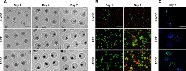
Figure 1. Self-assembly of HUVEC, HFF and ADSC monoculture spheroids after 1, 4 and 7 days of culture. (A) Light microscopy, (B) live/dead staining after 1 and 7 days of culture, scale bar = 200 μm. (C) Cleaved caspase-3 IHF after 7 days of culture, scale bar = 50 μm.
Download figure:
Standard image High-resolution imageFormation of coculture spheroids
For the formation of coculture spheroids, different cell combinations (HUVEC/HFF, HUVEC/ADSC, HUVEC/HFF/ADSC) and different cell ratios were tested (figure 2). To evaluate the aggregation behavior of the ratios, premixed solutions of the desired cell types and cell numbers were seeded onto the microwells. Cells lowered into the bottom of the well after 1–2 h. In all conditions cells started to aggregate spontaneously and after one day in culture, loosely aggregated microtissues were obtained (data not shown). These results showed that HUVEC can form spheroids when cultured in the presence of HFF, ADSC or a combination of both. The applied cell ratio influenced aggregation. Less aggregation was observed when more HUVEC than supporting cells (HFF and ADSC) were present (2/1, 5/1, 9/1). Furthermore, spheroids with these cell ratios were less uniform, smaller, more polygonal in shape and started to disintegrate from day 2, associated with a higher amount of cell debris (data not shown). In cell ratios where more ADSC than HUVEC are present, larger, and rounder spheroids were formed. For all cell combinations, the 1/9 ratio (indicated in figure 2) showed stable spheroids during the entire culture period of 10 days. Spheroids were round, and less cell debris was present.
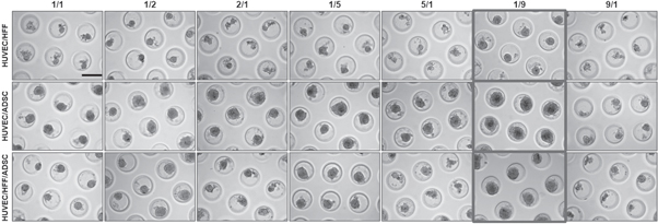
Figure 2. Light microscopic evaluation of spheroids formed by using different cell ratios of HUVEC/HFF, HUVEC/ADSC and HUVEC/HFF/ADSC. Evaluation on day 10 in culture. For HUVEC/HFF/ADSC a 1/1 ratio for example means 1/0, 5/0, 5. Scale bar = 200 μm.
Download figure:
Standard image High-resolution imageLive/dead staining revealed high cell viability in all coculture conditions with a 1/9 seeding ratio (figure 3(a)). Spheroids remained viable during the entire 10 days culture period. Cell dead is mostly observed at the periphery of the spheroids and in the detached single cells. In the core of the spheroids, few dead cells can be found but the majority remained viable (figure 3(a)). IHF for cleaved caspase-3 showed that the dead cells are apoptotic (figure 3(b)). In the coculture spheroids, less apoptotic cells were observed as compared to the monoculture spheroids (figure 1(c)). This indicates that HUVEC need to be cocultured with HFF, ADSC or a combination of both, to form spheroids that remained viable the entire culture period, in contrast to the monoculture spheroids (figure 1(b)). Haematoxylin eosin staining showed circular organized nuclei in the center (figure 3(c)). Based on these results, the 1/9 ratio was selected for all further experiments.
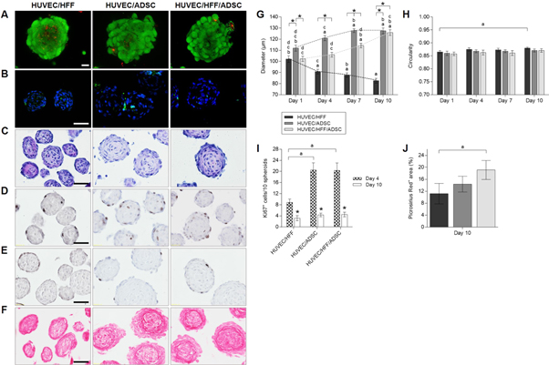
Figure 3. Overall morphology, viability, ECM production and proliferation of HUVEC/HFF, HUVEC/ADSC and HUVEC/HFF/ADSC spheroids. (A) Live/dead confocal images of day 10 spheroids, scale bar = 20 μm. (B) DAPI (blue) and caspase-3 (green) IHF of day 10 spheroids, scale bar = 50 μm. (C) Haematoxylin/eosin staining of day 10 spheroids, scale bar = 50 μm. (D) Ki67 IHF of day 4 spheroids and (E) day 10 spheroids, scale bar = 50 μm. (F) Picrosirius Red staining of day 10 spheroids, scale bar = 50 μm. (G) Diameter and (H) circularity of spheroids on day 1, 4, 7 and 10. Significant differences (p < 0, 05) were marked a compared to the same condition on day 1, b to day 4, c to day 7, d to day 10 and * when compared to other conditions at the same time point. (I) Number of Ki67 positive cells per 10 spheroids on day 4 and 10, significant differences were marked ap < 0, 05 compared to the same condition on day 4 and *p < 0, 05 compared the same condition at a different time point. (J) Picrosirius Red positive area (in %), significant differences were marked ap < 0, 05. All data are presented as mean ± 95% CI.
Download figure:
Standard image High-resolution imageSpheroid geometry was characterized by measuring the diameter and circularity (figures (g) and (h)). Evaluation of the diameter of the coculture spheroids after 1, 4, 7 and 10 days of culture (figure 3(g)), showed that HUVEC/HFF were significantly smaller than HUVEC/ADSC or HUVEC/HFF/ADSC spheroids. Moreover, HUVEC/HFF diameter reduced significantly in time, from an average diameter of 102.10 ± 12.82 μm on day 1 to an average diameter of 82.62 ± 9.09 μm on day 10. However, when ADSC were present, spheroids diameter significantly increased over time. For HUVEC/ADSC spheroids an increase from a mean diameter of 111.97 ± 2.72 μm on day 1 to 127.40 ± 2.65 μm on day 10 was measured. HUVEC/HFF/ADSC spheroids as well had a significant larger diameter on day 10 (125.92 ± 2.57 μm) compared to day 1 (102.24 ± 2.31 μm). Circularity remained stable around 87% (figure 3(h)). Only for the HUVEC/HFF spheroids a significant increase in circularity was observed on day 10 of the culture period in comparison to day 1, which correlates with the decrease in diameter.
Proliferation within the spheroids was evaluated by performing a Ki67 IHF which showed that Ki67+ cells were mostly located in the outer rim of the spheroids (figures 3(d) and (e)). On day 4, spheroids containing ADSC comprised a significantly higher number of Ki67+ cells (±20 cells/10 spheroids) than the HUVEC/HFF spheroids (±9 cells/10 spheroids), which correlates with the larger diameter of these spheroids (figures 3(d)–(i)). The number of Ki67+ cells significantly decreased in all experimental groups on day 10 (±3–4 cells/10 spheroids) and were only situated at the edge of the spheroids (figures 3(e) and (i)).
When assessing ECM production, Picrosirius Red staining demonstrated a larger positive area of collagen fibers in spheroids containing ADSC, suggesting a larger ECM production. Especially in the HUVEC/HFF/ADSC spheroids, where a significant difference was found compared to the HUVEC/HFF spheroids (19% versus 11% positive stained area) (figures 3(f) and (j)).
Vascularization in coculture spheroids
To locate the endothelial cells within the coculture spheroids, IHC analysis of the surface marker CD31 was performed (figure 4(a)). In HUVEC/HFF spheroids, HUVEC were prominently located at the surface of the spheroid and sparsely present in the center. When the coculture spheroids contained ADSC, HUVEC were not situated at the periphery but were distributed throughout the entire spheroid. A capillary-like network developed from day 4 in culture and remained intact the entire culture period (figure 4(a)), even up to day 20 (data not shown). HE staining of thin (2 μm) sections clearly showed the presence of lumina in all experimental groups (figure 4(b)). Cells surrounding these lumina stained positive for CD31 (figure 4(c)). Quantification of the CD31 IHC staining showed a higher CD31+ area in groups containing ADSC, and a significant difference for the HUVEC/HFF/ADSC (5, 45% CD31+ area) spheroids compared to the HUVEC/HFF spheroids (2, 74% CD31+ area) (figure 4(d)). Also, a higher number of lumina was observed in these ADSC containing spheroids, with a significant larger number within the HUVEC/HFF/ADSC (9 lumina/10 spheroids) compared to the HUVEC/HFF coculture (5 lumina/10 spheroids) (figure 4(e)).
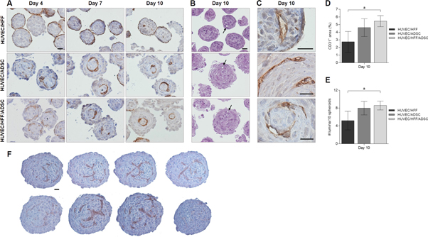
Figure 4. Vascularization within spheroids. (A) IHC localization of CD31 endothelial cell marker within HUVEC/HFF, HUVEC/ADSC and HUVEC/HFF/ADSC spheroids on day 4, 7 and 10. (B) HE staining of 2 μm sections, showing presence of lumina (arrows). (C) Higher magnification of positive CD31 staining surrounding lumina, indicating capillary-like structures. Scale bars = 20 μm. (D) Quantification of CD31+ area and (E) number of lumina present per 10 spheroids in all experimental conditions on day 10, significant differences were marked ap < 0, 05. (F) Four sequential sections (5 μm each) of two large HUVEC/HFF/ADSC spheroids, scale bar = 20 μm.
Download figure:
Standard image High-resolution imageWhen an alternative seeding technique was applied, i.e. delayed seeding of the HUVEC, similar results were obtained. 24 h after the addition of HUVEC to an earlier formed ADSC spheroid, HUVEC migrated to the center of the spheroid. The used seeding technique had no influence on the organization of the HUVEC within the spheroid (data not shown). A parameter that did have an impact on HUVEC organization, was the size of the spheroids. When spheroids with a larger diameter (>170 μm) were formed, by seeding 1.0 × 10⁶ cells onto the microwell, resulting in approximately 350 cells per spheroid, another type of network was developed. Figure 4(f) displays 4 sequential section (5 μm thick each) of two HUVEC/HFF/ADSC spheroids with larger diameter, showing what appears to be a more branched capillary-like network throughout the entire spheroid.
To assess if the HUVEC are the proliferating cells shown in figures 3(d) and (e), a double staining for Ki67 and CD31 was performed (figure 5). Results show that the majority of the proliferating cells are not HUVEC, only few cells were Ki67+ and CD31+.
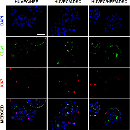
Figure 5. Double staining of CD31 and Ki67 within spheroids. IHF localization of CD31 (green) endothelial cell marker and Ki67 (red) proliferation marker within HUVEC/HFF, HUVEC/ADSC and HUVEC/HFF/ADSC spheroids on day 10. Nuclei were stained with DAPI (blue), scale bar = 50 μm.
Download figure:
Standard image High-resolution imageFor further evaluation of capillary-like structures, and to check the resemblance with in vivo-capillaries, 10 day old spheroids were examined by TEM (figure 6). In spheroids of all conditions, endothelial cells showed intracellular vacuole formation (black arrows figure 6(a), asterisks figure 6(b)) and lumina were present (figures 6(a), (c)–(f)), also microvilli-like cytoplasmic luminal protrusions were observed (white arrows figure 6(a)). Nuclei of endothelial cells (black arrows figure 6(c)) were arranged around the lumen. Figures 6(d) and (e) shows tight junctions (black arrows) between EC surrounding an intercellular lumen (asterisks). Figure 6(f) shows a capillary structure where a clear basement membrane is present (black arrow figure 6(g)), on the luminal side pinocytotic vesicles were seen (black arrows figures 6(g) and (h)), indicating transcapillary transport and thus active microvessels. Weible–Palade bodies, specific structures found in endothelial cells of vessels containing von Willebrand factor, were also detected (asterisks figures 6(g)–(j)).
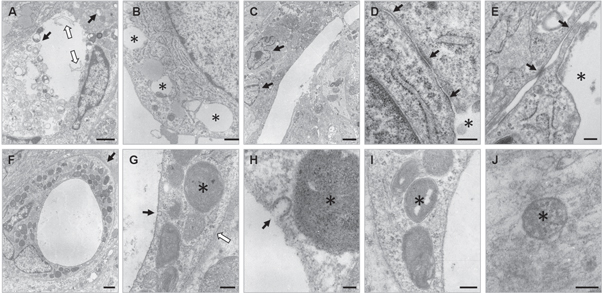
Figure 6. Evaluation of capillary-like structures with transmission electron microscopy. (A) Lumen with cytoplasmic protrusions (white arrows) and intracellular vacuoles (black arrows) within HUVEC/HFF spheroid, scale bar = 1 μm. (B) Intracellular vacuoles (asterisks) in HUVEC/ADSC spheroid, scale bar = 500 nm. (C) Two nuclei of EC (black arrows) surrounding lumen in HUVEC/HFF/ADSC spheroids, scale bar = 2 μm. (D), (E) Tight-junction (black arrows) between two EC surrounding an intercellular lumen (asterisks) in HUVEC/HFF/ADSC spheroids, scale bar = 200 nm. (F) Capillary/microvascular structure in HUVEC/HFF/ADSC spheroid with clear basement membrane (black arrow), scale bar = 1 μm. (G) Pinocytotic vesicle (black arrow), Weible–Palade bodies (WPBs) (asterisk) and basement membrane (white arrow), scale bar = 200 nm. (H) Pinocytotic vesicle (black arrow) and WPB (asterisk), scale bar = 50 nm. (I), (J) WPBs (asterisks), scale bars = 200 nm and 100 nm, respectively.
Download figure:
Standard image High-resolution imageFusion
In tissue engineering, microtissues are used as building blocks for the assembly of larger tissue constructs. Therefore, their potential to fuse was assessed in suspension culture (in U-shaped wells of a 96 well culture plate with cell-repellent surface) or within a hydrogel (Matrigel). For at random assembly in suspension culture, spheroids harvested on day 1 or day 10 were seeded in U-shaped wells. Light microscopic evaluation showed that 1 day old, and 10 day old (data not shown) spheroids started to fuse after 6 h of culture, fusion was completed within 24 h and after 96 h, a rounded construct was obtained (figure 7).
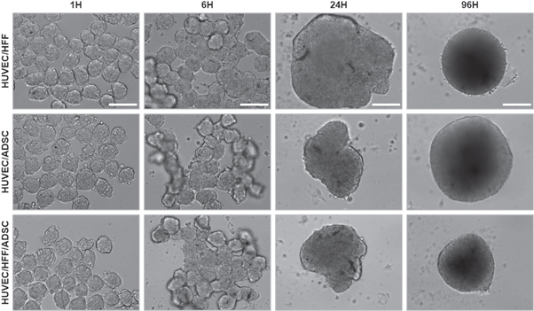
Figure 7. Light microscopic evaluation after fusion of 1-day-old spheroids. Fusion of HUVEC/HFF, HUVEC/ADSC and HUVEC/HFF/ADSC spheroids was evaluated 1, 6, 24 and 96 h after seeding of the spheroids. Scale bars = 200 μm.
Download figure:
Standard image High-resolution imageIHC showed that after fusion of 1-day-old spheroids, spheroids formed one unit, no individual spheroids remained visible and capillaries were present throughout the entire construct (figure 8(a)). Fusion of 10 day old spheroids resulted in a construct where the margins and structure of the original individual spheroids were still visible, histological staining showed capillary-like structures within the original spheroids and in between the individual spheroids, indicating inosculation of the existing capillaries of the different separate spheroids (figure 8(b)).

Figure 8. Capillary-like network formation in fused constructs. Spheroids were fused in suspension, fused construct was evaluated after 96 h by IHC localization of CD31 endothelial cell marker. (A) Fused construct obtained by seeding 1 day old spheroids, (B) fused construct obtained by seeding 10 day old spheroids, dotted lines show the margins between the original individual spheroids. Overview scale bar = 100 μm, 40x objective magnification scale bar = 20 μm.
Download figure:
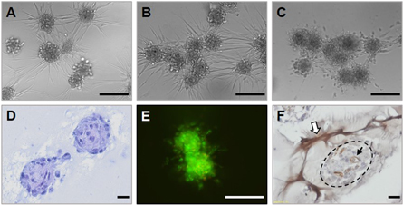
Standard image High-resolution imageAt random assembly of spheroids in a hydrogel was performed by mixing HUVEC/HFF/ADSC spheroids with Matrigel. After 18 h, sprouting was observed and spheroids started to connect (inosculation of endothelial sprouts) (figures 9(a)–(d)), after 24 h several spheroids started to fuse (figure 9(b)) and fusion was completed after 96 h (figure 9(c)). Spheroids also remained viable the entire culture period (figure 9(e)). CD31 staining showed that sprouts were positive for CD31, indicating formation of a vessel network through endothelial sprouting (white arrow figure 9(f)). Capillary-like structures within the spheroids remained present after encapsulation in Matrigel (black arrow figure 9(f)).
Figure 9. Fusion of spheroids in Matrigel. Evaluation of HUVEC/HFF/ADSC spheroids fused in Matrigel (A) after 18 h, (B) 24 h and (C) 96 h of culture, scale bars = 200 μm. (D) HE staining after 24 h, scale bar = 20 μm. (E) Live/dead staining after 96 h, scale bar 100 μm and (F) CD31 staining after 96 h of culture, scale bar = 20 μm.
Download figure:
Standard image High-resolution image
Discussion
The engineering of a larger biological construct remains challenging due to the need for an extended vasculature for the diffusion of nutrients and disposition of metabolic waste products. We believe that the combination of bioprinting technology with self-assembling microvascularized units as building blocks, can answer the need for a microvascular network. In the present study, we developed (pre)vascularized microtissues, spheroids containing a capillary-network. Although beyond the scope of this study these spheroids might have the potential application as an in vitro model in angiogenesis or drug screening research [38, 39]. But in the context of modular bottom-up tissue engineering, spheroids will be used as micro-building blocks for the biofabrication of a vascularized macrotissue. With the use of a 3D-bioprinter, these building blocks can be directly assembled, layer-by-layer, in a designed configuration with high spatial control. Therefore, uniformity of the spheroids is important, comparable shapes and sizes and an optimal diameter for disposition by the print needle (smaller than 200 μm) are required. A high-throughput technique was applied for the first time to generate vascularized spheroids. Although 3D microtissues can be created in several other ways, using e.g. pellet culture, spinner flask culture, hanging drop method, etc, the main disadvantages of these techniques are the homogeneity of the spheroids, size control, the quantity of the produced spheroids and the intensive manual labor for the exchange of culture medium and spheroid harvesting [40].
HUVEC were selected as endothelial cell type, for their widely known application in in vitro culture systems for angiogenic research. However, another interesting endothelial cell type are human microvascular endothelial cells (HMVEC), especially considering their potential to be an autologous cell source for the future creation of a personalized construct [41]. Within 24 h, HUVEC aggregated but no stable microtissues could be formed. Spheroids started to disintegrate after 48 h of culture and cell death already manifested. This was also demonstrated by Dissanayaka et al, where HUVEC alone were unable to organize into 3D microtissues and were not viable for more than 12 h, however when cocultured with dental pulp stem cells, stable microtissues were formed (±300 μm diameter) and HUVEC organized into a vascular-like network [42]. In a study by Korff et al, HUVEC were capable to form spheroids up to 4 days of culture, but spheroids of 2250 cells were formed, which is 10 fold the amount used in our study [43]. Above all, the geometry of these larger spheroids is not ideal to function as building blocks for bioprinting in contrast to the spheroids generated in this study.
It has been reported that the combination of ECs and other cell types such as smooth muscle cells, fibroblasts or pericyte-like cells, is necessary for the establishment of a vascular network, as the combination with supporting cells mimics the in vivo situation [20, 29, 43, 44]. To ameliorate vascular spheroid formation, coculture spheroids were generated. Fibroblasts and ADSC were used as stromal cell types in combination with HUVEC. The choice of both cell types was again motivated by their potential to be an autologous cell source, as they can be harvested from patient-derived material [45]. It has been described that ADSC can function as pericyte-like cells, as they are able to express alpha smooth muscle actin and angiogenic factors for the stimulation of endothelial cell proliferation and migration [46]. HUVEC themselves can also have an impact on the supporting cell types. As described by Saleh et al and Lozito et al, mesenchymal stem cells are impacted by soluble factors secreted by EC, the extracellular matrix of EC and the cell–cell contacts between EC and MSC [47, 48]. When MSC are exposed to the matrix secreted by HUVEC, in particular to heparan sulfate proteoglycans, an increase of EC- and smooth muscle cell markers in MSC is detected [48]. Moreover, paracrine factors secreted by HUVEC have a positive impact on MSC viability, proliferation, and colony formation due to impact of several mediators as fibroblast growth factor, Wnt, platelet derived growth factor, transforming growth factor-β, BMP, Notch, and Ephrin [47]. The combination of HUVEC with fibroblasts (HFF), ADSC or both, led to the formation of stable, round spheroids. Different HUVEC/HFF, HUVEC/ADSC and HUVEC/HFF/ADSC ratios were tested. Spheroids with a higher proportion of HUVEC, displayed poor aggregation and morphology. This was described before by Ma et al, where application of a higher proportion (>50%) of HUVEC than MSC, prevented pellet formation [49]. For all experimental conditions, a 1/9 ratio (=1/4, 5/4, 5 for the triculture) resulted in the formation of round spheroids, stable up to 10 days in culture. After aggregation, the viability of the cells within the spheroid remained high during the entire culture period, little to no cell death in the core of the spheroids was observed. The cells that do die, die from apoptosis. When spheroids were encapsulated in Matrigel, spheroids remained viable. Furthermore, all spheroids of ±262 cells generated in our study possess a favorable diameter for the application as units for bioprinting (all average diameters <130 μm). HUVEC/HFF spheroids were the smallest (±82.62 μm) and showed a decrease in diameter with increasing time in culture. A decreased diameter can be explained by the process of compaction, due to the increasing cell–cell contacts within the spheroids over time [35, 50]. The lack of spheroid growth correlates with the low number of proliferative cells (±9 cells/10 spheroids). Also, HUVEC/HFF spheroids displayed the lowest Picrosirius Red+ area of all three experimental conditions, which indicates a lower ECM production. The presence of ADSC in the cocultures, resulted in larger spheroids (±125 μm), and the diameter increased with increasing time in culture. As described by others, the coculture of endothelial cells with stem cells can stimulate stem cell proliferation and factors secreted by ADSC specifically can stimulate the proliferation of HUVEC [51, 52]. Double staining of Ki67 and CD31 showed that the majority of the proliferating cells are not HUVEC, only a few Ki67 positive cells were also CD31 positive. As ADSC containing spheroids possessed a significantly larger number of Ki67+ cells on day 4 of the culture period in comparison to the HUVEC/HFF spheroids, the majority of the proliferating cells are likely to be the ADSC. Ki67+ cells were (in all conditions) mainly found at the periphery of the spheroids. The manifestation of a proliferative rim within microtissues can be attributed to the optimal exchange of oxygen and contact with the culture medium in this region, also the pH in this region of the spheroid is closest to the physiological pH, in contrast to the center of the spheroid, which exhibits a more acidic pH [5]. Furthermore, spheroids containing ADSC displayed a higher Picrosirus Red+ area, indicating a higher ECM production. The diameter seems to stabilize after 10 days in culture, which correlates with the number of Ki67+ cells, which is significantly lower than on day 4 for all experimental conditions.
The organization of HUVEC within spheroids differed between the different experimental conditions. In HUVEC/HFF spheroids, HUVEC were mostly situated at the periphery in contrast to the HUVEC/ADSC and HUVEC/HFF/ADSC spheroids, where HUVEC were divided throughout the entire spheroid, forming a capillary-like network. This migration of HUVEC could be explained by the presence of ADSC. Skiles et al showed that factors secreted by ADSC, such as VEGF, stimulate HUVEC migration [52]. Also MMPs secreted by the ADSC can play an important role in migration of HUVEC, as ADSC secrete MMPs that modulate the ECM, stimulating HUVEC to migrate, promoting angiogenesis [53]. To check if the seeding method had an influence on HUVEC organization within the spheroid, the delayed seeding technique, was tested. Instead of seeding a premixed heterogeneous cell suspension onto the microwells, first an ADSC single cell suspension was seeded and 24 h later, HUVEC were added. Both seeding techniques resulted in the same central organization of the HUVEC, demonstrating the ability of the HUVEC to migrate through the already existing ADSC spheroid. A different organization of the HUVEC was observed in spheroids of ±350 cells with a larger diameter (diameter >170 μm), where a more branched capillary-network was created. This could be explained by the lower levels of oxygen at the center of the larger spheroids. Hypoxia can induce angiogenesis by upregulation of HIF-1a which regulates different pro-angiogenic pathways [54, 55]. A comparable network is obtained when small spheroids are fused.
Regarding the quantification of the CD31+ area in the different culture conditions, ADSC containing spheroids presented a larger CD31+ area compared to the HUVEC/HFF spheroids. Also, a larger number of lumina were observed, suggesting a more prominent capillary-like network. Lumen formation, or tubulogenesis, occurs during the processes of vasculogenesis and angiogenesis. The start of vascularization in vitro often resembles the process of vasculogenesis, which occurs during embryonic development, where isolated endothelial (precursor) cells aggregate to form a capillary plexus [56]. In tissue engineered constructs, vessel formation also starts from the assembly of isolated EC dispersed throughout a scaffold or a spheroid, which will spread and form linear structures wherein endothelial lumina will form. Evaluation of the spheroids by TEM showed lumen formation in the cytoplasm of individual cells and in the intercellular space, as well as the presence of WPBs, pinocytotic vesicles, and a clear basement membrane. There are different models of lumen formation reported in the literature, such as the coalescence of intracellular vacuoles, the exocytosis of intercellular vacuoles, apoptosis of endothelial cells in the middle or luminal repulsion [11, 57]. Although not further investigated in this study, TEM evaluation clearly shows the presence of vesicles and vacuoles, suggesting vacuole mediated lumen formation, as these pinocytotic vesicles can coalesce to form larger vacuoles. By successive fusion, a lumen can be formed and these capillaries can interconnect to create a network, as seen in the fused constructs. Instead of vasculogenesis, the extension of an existing vessel network will develop through angiogenic sprouting [58, 59].
As the future goal is the generation of a macrotissue, the micro-building blocks or spheroids need to be able to assemble. Therefore, vascularized spheroids were fused in suspension culture and within a hydrogel (Matrigel), regarding the future need for a hydrogel as a bio-ink for 3D bioprinting. Spheroids in suspension were completely fused within 24 h and after 96 h a branched capillary-like network throughout the entire fused construct was found, similar to the network found in larger spheroids (diameter >170 μm). When day 10 spheroids were combined, the margins of the original individual spheroids were still visible, but in between them, newly formed vessels were detected, which indicate the inosculation of consisting capillaries of adjoining microtissues within 4 days of culture. Even when embedded in Matrigel, spheroids were able to connect with neighboring spheroids and fusion started from 18 h in culture. This was also described by Annamalai et al, where microtissues fused in suspension as well as in a hydrogel and capillaries inoculated within one week of culture [60]. It has also been reported that multicellular vascularized spheroids can even function as building blocks for larger diameter vessels, as they can fuse together after placing them in tubular structures [61]. These results confirm the usefulness of spheroids as building units for a larger construct.
Conclusion
Our data shows for the first time that prevascularized building blocks for bioprinting applications can be fabricated. By balancing several parameters, such as the used seeding technique, cell number per spheroid, different cell type combinations and applied cell ratios, we have demonstrated the successful high-throughput fabrication of self-organized vascularized spheroids with bioprinting-compatible geometry. This study presented that endothelial cells can form viable, circular, and stable spheroids when combined with supporting cells (HFF, ADSC) in a 1/9 cell ratio. The ADSC containing spheroids, especially the triculture HUVEC/HFF/ADSC, possess a higher angiogenic capacity than the HUVEC/HFF and HUVEC/ADSC spheroids. Although this difference was only significant compared to the HUVEC/HFF spheroids. Moreover, the spheroids have the ability to fuse in suspension as well as in a hydrogel. Future work will include the search for a suitable hydrogel bio-ink, to deposit the multicellular vascularized spheroids by 3D bioprinting.
Acknowledgments
The authors would like to thank Professor Dr Jan Vanfleteren (Centre for Microsystems Technology) for kindly providing the PDMS molds and Leen Pieters, Greet De Smet, Johanna Aernoudt and Toke Thiron (Ghent University) for their technical assistance. We would also like to acknowledge Dr Isabel Pintelon (Antwerp Centre for Advanced Microscopy) for the confocal microscopy imaging.
All authors declare no conflict of interest.
DH acknowledges the Research Foundation Flanders (FWO) for supporting a Research Grant (1510414N) and Ghent University (Special Research Fund, BOF) (01B02315). MI and DH acknowledge the Erasmus Mundus Action 2 Project Basileus V for a scholarship. Research in the KDV group is supported by FWO-Vlaanderen (1506218N, 1507118N and G051918N) and Ghent University (Special Research Fund, BOF 14-GOA-019).