

Abstract
Three-dimensional (3D) printing offers potential to fabricate high-throughput and low-cost fabrication of microfluidic devices as a promising alternative to traditional techniques which enables efficient design iterations in the development stage. In this study, we demonstrate a single-step fabrication of a 3D transparent microfluidic chip using two alternative techniques: a stereolithography-based desktop 3D printer and a two-step fabrication using an industrial 3D printer based on polyjet technology. This method, compared to conventional fabrication using relatively expensive materials and labor-intensive processes, presents a low-cost, rapid prototyping technique to print functional 3D microfluidic chips. We enhance the capabilities of 3D-printed microfluidic devices by coupling 3D cell encapsulation and spatial patterning within photocrosslinkable gelatin methacryloyl (GelMA). The platform presented here serves as a 3D culture environment for long-term cell culture and growth. Furthermore, we have demonstrated the ability to print complex 3D microfluidic channels to create predictable and controllable fluid flow regimes. Here, we demonstrate the novel use of 3D-printed microfluidic chips as controllable 3D cell culture environments, advancing the applicability of 3D printing to engineering physiological systems for future applications in bioengineering.
Export citation and abstract BibTeX RIS
Introduction
Encapsulation of cells in three-dimensional (3D) hydrogels creates a biomimetic 3D microenvironment such that encapsulated cells experience cell–cell and cell–matrix interactions which more closely mimic those in the body than two-dimensional (2D) cultures [1, 2]. This biomimetic microenvironment results in cell behavior and multicellular structures which are more representative of the in vivo situation [3–5]. Several tissue-specific models have been developed, most notably vascular tissue as well as brain and liver tissues [6]. Cancer tissues, including breast and lung tumors, have also been modeled using this approach [6]. The use of microfluidics as a platform for cell-laden 3D hydrogels offers a significant advantage over traditional 2D static cultures for use in biomedical research, significantly impacting tissue engineering (including organ-on-a-chip devices), biodiagnostics, and drug screening. Incorporation of these 3D constructs into microfluidic devices allows for continuous perfusion of nutrients as well as precise spatiotemporal control over delivery of signaling factors (such as biomolecule gradients) while maintaining the ability to image the cells in vitro [6]. Such technologies and their potential for the field of bioengineering have been reviewed in several articles [6–8].
Microfluidic devices are most commonly fabricated from polydimethylsiloxane (PDMS) [7]. Fabrication of such devices requires UV lithography or milling to create a master mold and soft lithography with PDMS to make an imprint of the master, followed by a final bonding step to create fluid channels [9, 10]. However, this technique requires several labor-intensive steps and specialized equipment, resulting in high monetary and time costs. Photolithography is generally performed in a clean room to avoid defects in small features caused by particles in the air; this introduces another significant cost and makes the process impractical in many research labs. Further, the photolithography master fabrication process requires use of highly toxic photoresists, introducing health hazards and a negative environmental impact when the materials are disposed. The devices are also limited to '2½-D', where microfluidic channels are formed in 3D but are limited to 2D complexity without addition of multiple fabrication steps.
The use of 3D printing for microfluidics has the potential to revolutionize this field by minimizing the labor and costs required for device fabrication, improving accessibility of the technology for researchers and home users alike [10]. 3D printing is a relatively fast and user-friendly alternative to traditional fabrication techniques, offering the ability to rapidly create structures in desired geometries (comparable to PMMA and PDMS molded devices) using a variety of printable materials [11–15]. The processing time required to progress from design to functional device via traditional techniques can take several days while the 3D printing fabrication process presented here took only a few hours (though achieving higher resolution requires a longer printing time) with a low material cost ($0.80 per chip). This simplified approach, involving computer-aided design (CAD) and 3D printing, can accelerate the process of several iterations (design, fabrication, testing, and redesign). This rapid iterative process reduces labor costs compared to conventional methods which require production of a new photomask and photolithography in order to make even minor changes to the design. In addition, complex 3D structures which require additional fabrication steps and layer-by-layer assembly, or those which may be impossible to fabricate using traditional techniques, can be designed using CAD software and produced easily and rapidly with 3D printing.
Early 3D printing studies for microfluidics relied on fused deposition modeling in which a material is extruded and deposited onto a substrate [16]. More recently, stereolithography (SLA) offers high resolution and optically transparent printable materials via consumer-grade, 'desktop' instruments. Several recent studies have demonstrated the powerful emerging capabilities of 3D-printed microfluidic devices in terms of precise and reproducible control of fluid flow. 3D printing has been used to fabricate molds which may be used to create PDMS architectures [17] and PDMS-glass microfluidic devices [18–21]. 3D printing has also been used to fabricate monolithic microfluidic chips—termed unibody lab-on-a-chip devices)—in a single step [22, 23]. Multi-jet modeling and SLA processes can produce channel sizes down to 100 μm [11]. One study implemented an integrated valve structure inside a microfluidic device, in contrast to previously-reported devices with passive elements only [24]. Another study reported 3D-printed valves, switches, and pumps which replicate the function of syringe pumps and off-chip valves [12]. Microfluidic interconnects were also fabricated with direct multi-material 3D printing in order to integrate a flexible gasket with rigid clamps [25]. 3D printing has been used to integrate microfluidic devices with a solid acoustic wave-driven pump [26]. There is also demonstrated potential to fabricate modular devices which may be assembled by the user [27, 28], creating an opportunity for commercial mass production of microfluidic devices [10]. Recent applications of 3D-printed fluidic devices include chemical sensing [29, 30], nucleic acid hydrolysis [31], control and monitoring of chemical synthesis reactions [16, 32, 33], formation of nanoparticles [34], microplasma formation [35], micromixing [30], and droplet generation [36].
Biological applications of microfluidics range from chemical and biological assays to point-of-care diagnostics [37–41], representing a new subfield of microfluidics with much to gain from the use of rapid prototyping and 3D printing fabrication techniques [42]. 3D-printed chips have been developed to isolate and identify influenza hemagglutinin for disease diagnostics [43], methicillin-resistant Staphylococcus aureus [44] and Escherichia coli to screen for food contamination [45], and cells from biological samples based on a phenotype of interest [46]. Other chips have been designed to examine drug transport across membranes and the effect of transported drugs on cells cultured on the membrane [47]. Several studies have demonstrated the use of 3D bioprinting to pattern microfluidic channels followed by cells deposited directly into the channels [48–51], including co-cultures of multiple cell types [52]. 3D printing has also been used to generate cell cultures with hepatic sinusoid-like structures within fluid channels [53]. An important consideration, particularly for the application of 3D-printed microfluidics to cell culture, is the optical transparency for high-quality transmitted light and epifluorescence imaging of cells and tissue structures. Although low optical transparency and light scattering tend to be an issue with 3D-printed materials, particularly when surface defects are present, this issue has been addressed by polishing or by coating the surface with a material of similar refractive index [10]. With the printing capabilities of 3D printers rising, the range of printable materials expanding, and equipment costs falling to affordable prices, the technology is becoming increasingly accessible, offering a practical alternative to conventional methods which could revolutionize the field of microfluidics, particularly for biological applications [54].
However, in order to realize the full potential of 3D cellular cultures in microfluidics and ultimately foster wider adoption of this approach by biologists and clinicians, bioassay platforms must be designed to be user-friendly to lower the barrier to entry for these end users [8]. Here, we demonstrate the fabrication of microfluidic chips using desktop SLA and industrial inkjet-style 3D prototyping and integrate cell encapsulation in 3D hydrogel posts within the microfluidic channels. The platform presented here leverages the simple design and fabrication process of 3D printing as well as a versatile photo-crosslinking approach to fabricate cell-laden hydrogel constructs with controllable geometries. We aim to demonstrate a simple, user-friendly approach to fabrication of microfluidic chips and their use as a platform for scaffold-guided tissue engineering. This work demonstrates a highly applicable and useful biomedical application of 3D-printed microfluidic devices for creating 3D biomimetic culture environments with controllable geometries which may ultimately be used to for micro-physiological tissue engineering. This approach will make these devices accessible to users across several fields, including basic scientists and clinicians, and foster innovation in the field of bioengineering.
Methods
Unibody 3D microfluidic chip printing
The 3D microfluidic device was designed in Tinkercad (Autodesk, Inc., San Rafael, CA), a free online CAD application. The channel height was set as 500 μm and the channel geometries, inlets, and outlets were designed as a unibody microfluidic chip. The .stl file was loaded into PreForm (Formlabs, Somerville, MA) and supports were generated automatically with 1.0 density value and 0.60 mm point size with no internal supports. The device was fabricated using a Form 1+ SLA 3D printer (Formlabs, Somerville, MA) with clear photoreactive resin (V02, Formlabs) and a layer thickness of 0.05 mm. The volume of resin used was 5.4 ml (Chip 1, with straight channels) and 3.1 ml (Chip 2, with fluid mixing channels); the duration of printing was 2 h 40 min (Chip 1) and 2 h (Chip 2). The 3D printing process uses a laser beam to solidify the resin layer-by-layer (figure 1). The design was printed in a vertical configuration, which has been shown to be superior for creating microchannel arrays in terms of hydrodynamic characteristics [55].
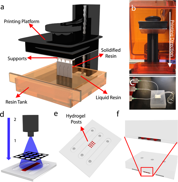
Figure 1. Fabrication and application of 3D-printed microfluidic devices. (a) Illustration of SLA printing process. During the fabrication, the chip was connected to a supportive base on the printing platform in order to stabilize the chip during printing. The printing resolution was set as 0.05 mm. A thin layer of liquid resin inside the resin tank was solidified by a high-precision laser beam emitted from below the tank. (b) Printer with front cover opened showing the printing platform at the top and resin tank at the bottom. The dimension of printer is 30 cm × 28 cm × 45 cm, and weighs 8 kg. The printing direction is downward from the printing platform toward the resin tank. (c) Image of channel washing method. After fabrication, the 3D-printed chip was transferred to an IPA tank for 1 min of surface washing. Inlets were connected to a syringe pump, and IPA was flowed through the channels and collected in a flask to remove the uncured resin within the channels. The chip was placed into a 55 °C oven for channel drying. (d) Application of hydrogel post formation. Hydrogel prepolymer solution was pumped into the channel and a photomask was aligned onto the bottom surface of the channel. UV light was applied through the photomask to crosslink the hydrogel only in the transparent areas of the mask. (e) After gelation, DI water was pumped into the channel to remove any uncrosslinked hydrogel, leaving hydrogel posts within the channel. (f) Illustration of a cross-section of the 3D chip with hydrogel posts. The thickness of the upper layer is 3 mm; the channel layer and bottom layer are 500 μm.
Download figure:
Standard image High-resolution imageOptimization of unibody microfluidic chip post-processing
After the printing was finished, the surface of the chip was washed in isopropanol (IPA) for 1 min (Chip 1) and 30 s (Chip 2). IPA was flowed from inlet to outlet using a syringe pump system (New Era Pump Systems Inc., Farmingdale, NY) and three syringes (syringe with Luer-Lok tip, BD, Franklin Lakes, NJ) connected with silicone tubing (Tygon Silicone Tubing, 1/32'ID x 3/32'OD, Cole-Parmer, Vernon Hills, IL) at an optimized flow rate of 500 μl min–1 for a duration of 5 min. Deionized water was pumped through the channels for the same period of time to remove all traces of IPA. To improve optical transparency and reduce light scattering at the surface, chips were wet sanded with 800-grit sandpaper (3M, St. Paul, MN) then with 1200-grit sandpaper (3M) until the surface was smooth. The chips were further polished on corkboard with acrylic plastic polish (Novus, St. Paul, MN). After washing, the chips were placed in a 55 °C oven for 3 h (Chip 1) and 2 h (Chip 2) until fully dried. The channels and outer surfaces were soaked in mineral oil (Sigma, St. Louis, MO) to further improve optical imaging.
In order to optimize the flow rate for removing uncured resin following printing, several flow rates and times were tested. After 1 min of chip surface cleaning, the channels were washed with IPA using a syringe pump for a set time, tIP, followed by deionized water for the same period of time, tDI = tIP. Three different rates (25, 100 and 500 μl min–1) were tested with three washing times (1, 3, and 10 min). After washing, the chip was heated at 55 °C for 5 h to complete the drying process. After drying, the 1% (v/v) food dye was pumped into the channels to visualize the area fraction of the channel which had been cleared of resin. Arial view images of the channels filled with dye solution were analyzed using MATLAB (MathWorks) to determine the fraction of the channels that was filled with dye. The red channel of each image was isolated and the dye area was separated from the background image by setting a brightness threshold to generate a binary mask from the image. A user-specified channel width was compared with the measured channel width in pixels and this ratio was used as a conversion factor between pixels and millimeters. The filled channel fraction was calculated as the ratio between the area where dye is present (in millimeters) and the known area of the channels.
Channels were coated with embryo tested mineral oil (Sigma, St. Louis, MO) which has a refractive index of 1.47 [56] and was chosen to closely match that of the 3D-printed resin. This technique reduces the light scattering effect of the chip to improve imaging of fluorescently stained biological samples within the device as it is not possible to polish the inside surfaces of the channels [10]. Microfluidic devices were incubated in the mineral oil at room temperature for 30 min and then the oil was aspirated from the channels. Mineral oil was applied to the outside surfaces of the device using a sterile Kimwipe immediately prior to microscopic imaging.
Fabrication of bonded microfluidic chips
Microfluidic chips were designed as described previously using CAD software with the open along one face. The design was printed on an Objet30 Prime 3D printer (Stratasys, Edina, MN) with high quality (16 μm layer thickness). The supports were removed using the water jet system as specified by the manufacturer (Stratasys, Eden Prairie, MN).
PDMS was prepared with a 10:1 ratio of elastomer to curing agent and degassed for 20 min. 1 ml of PDMS was dispensed onto a clean and dry glass slide and spin coated at 1000 RPM for 1 min with a ramp speed of 108 RPM s−1. The 3D-printed part was immediately pressed onto the PDMS and the chip was cured for 1 h at 100 °C.
Formation of cell-encapsulating hydrogel posts
Gelatin methacryloyl (GelMA) was synthesized as described previously [57]. Briefly, a reaction between gelatin and methacrylic anhydride was followed by freeze drying. The freeze-dried material was dissolved at 5% in cell media (Dulbecco's Modified Eagle medium with 10% fetal calf serum and 1% penicillin) with 1% Irgacuare 2959 photoinitiator (2-Hydroxy-4'-(2-hydroxyethoxy)-2-methylpropiophenone, Sigma, St. Louis, MO). For cell encapsulating experiments, mc-3T3 cells (ATCC, Manassas, VA) were trypsinized according to the ATCC protocol and a single cell suspension was mixed into the prepolymer solution. Cells were then mixed with the hydrogel prepolymer solution at a concentration of 3 × 10⁵ cells ml−1. The mixture was loaded into a microfluidic channel by pipette and crosslinked by applying UV light through a photo-opaque mask for 25 s at a power of 1.2 W and a distance of 9 cm from the source to the bottom face of the chip (0.5 mm thickness) (figure 1(d)).
Once the gel posts were formed (figure 1(e)), cell media was pumped through the channel at a rate of 100 μl min−1 for 1 h in order to remove the un-crosslinked prepolymer solution and cytotoxic photoinitiator. To maintain cell viability over time, the chip was incubated at 37 °C and 5% CO2 with cell media flowing continuously through the chip at a rate of 5 μl min−1.
Optimization of cell-laden hydrogel formation
In order to optimize the hydrogel formation and cell encapsulation within the microfluidic chip, cells were stained with Qtracker 625 Cell Labeling Kit (Life Technologies, Carlsbad, CA). Cell-laden hydrogels were cured for six different UV exposure times (20, 25, 30, 35, 40, 45 s) at a distance of 9 cm from the light source and a UV power intensity of 2.3 W cm−2 (1.2 W). The hydrogels were exposed to fluid flow at 50 μl min−1 for 1 h followed by 50 μl min−1 for long-term culture. Qtracker cells were imaged in the red channel; the green channel revealed the area within the field of view which was exposed to UV light (as the resin was observed to fluoresce weakly in the green channel following exposure to UV light). The number of cells retained in the hydrogel (i.e. the number of local maxima counted in the red channel image which are contained within the green fluorescent area) were counted. The exposure time resulting in a maximum number of cells retained in the hydrogel was used for all subsequent cell encapsulation experiments.
Evaluation of cell viability and proliferation
Cell viability was measured using a live/dead viability/cytotoxicity assay (Life Technologies, Carlsbad, CA). At day 0 (after the 1 h washing step), 1, 3, 5, and 7 time points, 8 μM calcein AM and 4 μM ethidium homodimer-1 in DMEM was injected into the channel and incubated at 37 °C for 45 min. Live cells were imaged using a GFP fluorescence filter for calcein; dead cells were imaged using a CY3 fluorescence filter for ethidium homodimer. Images were taken at five evenly-spaced slices between the top and bottom of each hydrogel, forming a Z-stack of images. The stack was projected into a single image (which is the summation of the pixel intensities of each corresponding pixel across the stack) using ImageJ. The pixel intensity maxima were counted using local maxima detection across ten hydrogel posts in each of three channels to determine the viability as the percentage of live cells relative to the total number of cells counted.
Qtracker was used to stain cells prior to encapsulation and track cell proliferation in hydrogel posts during long-term culture (7 d). Qtracker was prepared according to the manufacturer protocol with 0.5% of each reagent in complete cell growth media. Cells were incubated in the solution at 37 °C and 5% CO2 for 24 h prior encapsulation. Stained cells were then trypsinized and encapsulated as described previously. At days 0 (after the 1 h washing step), 1, 3, 5, and 7, the cells were imaged through a CY3 fluorescence filter to form a Z-stack of 5 images and returned to the incubator. A Z-projection image was generated as described previously and the pixel intensity maxima were counted across ten individual hydrogel constructs in each of three separate microfluidic channels at each time point.
Control hydrogels were prepared by pipetting 5 μl of cell-hydrogel solution between two 525 μm spacers then placing a glass slide over the droplet. The hydrogel was cured through a 500 μm slice of cured resin (to simulate the conditions in the microfluidic chip, where the UV passes through the resin wall before reaching the hydrogel). The glass slide with cured, cell-laden hydrogel was transferred to cell growth media in a 6-well plate. To wash out any photoinitiator, the media was changed three times with a 10 min incubation between each media change. The samples were then cultured under standard culture conditions and imaged as described for the microfluidic chips.
Results
Characterization of unibody 3D chip fabrication
The microfluidic chips were designed using Solidworks and printed using a Form 1+ SLA 3D printer with commercial clear resin at a 0.05 mm layer thickness. Chips were printed in a vertical orientation to increase the printing quality of the channels, which has previously been shown to yield greater dimensional conformity [55]. Printer settings and post-printing treatments were optimized to achieve consistent printing of high-fidelity microfluidic chips (table 1). The resin volume used per chip is 5.4 ml and the material cost of each chip fabrication was approximately $0.80. The chip is printed layer-by-layer in the resin tank: each layer is solidified by a laser beam emitted from the optical system below the resin onto a build platform on the opposite side (figure 1(a)). The printing platform moves upward between curing of each layer, building the design on the build platform in a downward direction (figure 1(b)).
Table 1. Parameters of 3D printing and post-printing treatment for unibody microfluidic chips.
| 3D-printing parameter | Chip 1 (straight channels) | Chip 2 (fluid mixing) |
|---|---|---|
| Resin volume used | 5.4 ml | 3.1 ml |
| Printing time | 2 h 40 min | 2 h |
| Resolution | 0.05 mm | 0.05 mm |
| Number of layers | 940 | 796 |
| Cost for each fabrication | $0.8046 (1 ml resin: $0.149) | $ 0.4619 |
| Post-printing treatment | Chip 1 (straight channels) | Chip 2 (fluid mixing) |
| Chip surface cleaning time | 30 s | 15 s |
| Channel washing time | 3 min | 1 min 30 s |
| Flow rate (channel washing) | 500 μl | 900 μl |
| Drying time | 3 h | 2 h |
| Drying temperature | 55 °C | 55 °C |
| Dye solution pumping rate | 100 μl min−1 | 100 μl min−1 |
The SLA printing process involves layer-by-layer photopolymerization of a liquid resin; this process leaves uncured liquid resin in the channels which must be cleared out prior to use. IPA was pumped through the channels using a syringe pump in order to clear the remaining uncured resin from the channel, followed by washing with DI water and drying in an oven (figure 1(c)). To optimize the parameters of this post-printing treatment, the channels were continuously washed with IPA for different time durations (tIP: 1, 3, and 10 min) with a syringe pump using different flow rates (Rflow: 25, 100, and 500 μl min−1) (figure 2(a)). To visualize the quality of channel formation, the fraction of the channel filled with a dye solution was measured as a function of IPA washing time (tIP) and flow rate (Rflow) (figure 2(b)). Results show that when the flow rate and washing time are increased, the area fraction of the dye solution also increased, representing a more thorough washing of the channel. The optimal parameters were found to be tIP = 3 min with Rflow = 500 μl min−1.
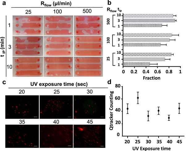
Figure 2. Optimization of channel cleaning and hydrogel formation. (a) Channels filled with dye for visualization of channel cleaning area after different IPA washing times (tIP, minute) and washing flow rates (Rflow, μl min−1). (b) Quantification of channel fill ratio after cleaning with three flow rates and three washing times. (c) Fluorescence images and (d) quantification of Qtracker-stained cells encapsulated in crosslinked GelMA posts using six different exposure times (20, 25, 30, 35, 40, 45 s) to identify the exposure time for optimal cell encapsulation.
Download figure:
Standard image High-resolution imageCharacterization of hydrogel post formation
Hydrogels were formed by pumping a GelMA hydrogel prepolymer solution with photoinitiator into the channels and crosslinking through a photomask (figure 1(d)). The uncrosslinked hydrogel was then washed away to reveal hydrogel posts (figure 1(e)). A cross-section of the chip with hydrogel posts is shown in figure 1(f).
To optimize the formation of cell-laden hydrogel constructs for 3D patterning of cells within the microfluidic devices, Qtracker-stained cells were encapsulated and counted following the washing step. Six UV exposure times (20, 25, 30, 35, 40, and 45 s) were applied to cure the 1 mm hexagonal hydrogels (figure 2(c)) and to measure the encapsulation efficiency as a function of UV exposure time (figure 2(d)). Results indicate that the a UV exposure time of 25 s was optimal for the following experiments in order to achieve high quality hydrogel constructs without applying excessive UV light, which may negatively impact cell viability.
Fluid mixing chip fabrication and application
Figure 3 compares the printing capabilities of the desktop-style Form 1+ SLA 3D printer (smallest layer height of 25 μm and laser spot size of 155 μm) and the industrial grade Objet30 Prime polyjet 3D printer (smallest layer height of 16 μm and 600 DPI, which corresponds to approximately 42 μm per resin droplet). To achieve the high resolution required for fluid mixing applications, the Objet30 Prime was used to print both diffusion (straight geometry) and herringbone mixing devices. In order to overcome the challenge of the support materials being difficult to remove from the channels, the chips were fabricated in an 'open face' configuration with one wall of the channels open to allow removal of the support. This face was then sealed by pressing into a spin-coated layer of PDMS on a glass slide. To demonstrate the capabilities of such complex microfluidic channels, a diffusion mixing channel was designed to mix two inlet flows in a central channel and expose three hydrogel constructs to either one of the two inlet fluids or a mixture of the two (figures 4(a) and (b)). Two inlets were mixed and flowed into the center channel, while the side channels experience flow from a single inlet (figure 4(b)). Circular hydrogel posts (figure 4(c)) were formed in the chambers as described previously using a photomask. The spacing between transparent areas on the UV photomask is equal to the spacing between chambers on the microfluidic chip, allowing multiple constructs to be formed in a single crosslinking step.

Figure 3. Printing quality by desktop (marked F) and industrial (marked O) 3D printers. (a) 500 μm raised structures intersecting at a 45° angle as printed by the Form 1+ (left, marked F) and Objet30 Prime (right, marked O). (b) 500 μm raised structures intersecting at a 20° angle as printed by the Form 1+ (left) and Objet30 Prime (right). (c) Raised structures with increasing width and spacing between 100 and 500 μm as printed by the Form 1+ (top, bottom right) and Objet30 Prime (middle, bottom left). (d)–(f) Three circular stepped structures with varying dimensions (left). Images show top and side views of the structures as printed by the Form 1+ (center) and Objet30 Prime (right).
Download figure:
Standard image High-resolution image
Figure 4. 3D chip for fluid mixing and hydrogel post formation. (a) 3D-printed mixing chip design: each inlet is connected to two channels, one is leading to the side channel and the other to the center channel where fluid mixing takes place. When two inputs, represented by red and blue dyes, are flowed into the mixing chip, the top chamber collects the blue dye solution only, the center chamber collects a mixture of the red and blue dye solutions, and the bottom chamber collects the red dye solution only. To fabricate microfluidic chips, the microfluidic channels are 3D-printed by the Objet30 Prime and this piece is bonded to a glass slide via a spin-coated PDMS layer. (b) Fluorescence image of hydrogels formed in channels. Two different mixing channels were fabricated: (c) a diffusion mixing channel and (e) a herringbone mixing channel, by modifying the CAD file to include herringbone structures on one surface. Fluid mixing was visualized by flowing a red and blue dye into the two inlets in the (d) diffusion mixing chip and (f) herringbone mixing chip. (g) Channel inlets in the diffusion and herringbone mixing channels (top); composite, red (R), and blue (B) images showing the chambers following the diffusion and herringbone mixing channels (below). (h) Pixel intensity profiles along a cross-section of the inlet to the mixing channel and in the chamber at the outlet (profile along the center of the channel is shown), as marked in (d) and (f). The red and blue channel pixel intensities across the channel were measured in both the straight channel and the herringbone channel. The approximately linear region at the center of each pixel intensity profile was selected and the slope determined to calculate the pixel gradient. (i) Pixel gradients at the inlet and chamber for the red and blue channels. Chamber values are averages over seven adjacent pixel intensity profiles with standard deviation bars. The straight (diffusion mixing) and herringbone mixing channels are compared.
Download figure:
Standard image High-resolution imageUsing the industrial grade Object30 Prime, both a diffusion mixing channel and a herringbone mixing channel of the same length were fabricated using the bonded approach to compare their performances (figure 4(a)). Both straight channels and channels with a herringbone micromixer design (according to guidelines described by Williams et al [58]) were fabricated successfully using this bonding approach (figures 4(c) and (e)). When cured, the result is microfluidic channels through which fluid can be flowed through two inlets, dyed blue and red, to visualize the fluid flow regime (figures 4(a), (d) and (f)). Images were taken across the entire channel and spliced in order to generate a continuous image of the mixing of the two inlets along the center channel (figures 4(d) and (f)). The dye intensity profile across the microfluidic channel was measured (i) at the inlet and (ii) across the chamber following the mixing channel in both the red and blue channels (figure 4(g)). The steepness of the pixel intensity gradient in the middle of the channel is inversely proportional to the degree of mixing at the sampled channel location (figure 4(h)). Figure 4(i) shows the pixel intensity gradients (change in pixel intensity per pixel unit) in the channel cross-sections due to diffusion mixing. These results indicate more efficient mixing achieved using the herringbone mixer, which is consistent with previous results reported in the literature.
Examination of cell viability and proliferation over time
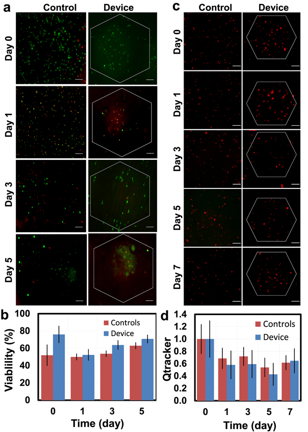
The cell viability of GelMA-encapsulated 3T3 cells was measured using a Live/Dead viability/cytotoxicity kit and imaging samples via fluorescence microscopy to measure fluorescence from calcein AM and ethidium homodimer-1, respectively. The cell viability was measured and compared to cell-laden GelMA hydrogels of the same height geometry formed on glass slides and incubated in static culture. The results at several time points over one week are shown in figures 5(a) and (b). The cell viability decreased slightly between days 0 and 1, likely due to the encapsulation process, but increased or remained constant over 5 days in both control hydrogels and in the microfluidic channel. Qtracker dye was used to stain cells prior to encapsulation and observe cell distribution and cell number continuously over one week. The cell population in individual gel posts showed the homogeneity of cell distribution within the constructs. The visible Qtracker points were counted over time and the results are shown in figures 5(c) and (d), demonstrating the same slight decrease between day 0 and day 1, but a steady cell population over 7 days.
Figure 5. Examination of cell viability and proliferation. (a) Cell viability over 5 days in hexagonal hydrogel constructs contained within the microfluidic device (right) compared to control hydrogels cultured on glass slides in static culture (left). Live cells are stained with calcein (green) and dead cells are stained with ethidium homodimer (red). Images are the summation of pixel intensities across five evenly-spaced Z-stack images captured between the top and bottom of the 3D hydrogel construct. Hexagonal UV-exposed areas are outlined in white in device images. Scale bar = 100 μm. (b) Quantification of cell viability in hydrogels cultured within the microfluidic device and in static culture controls. (c) Cell proliferation for 7 days in hexagonal hydrogel constructs contained within the microfluidic device and control hydrogels cultured on glass slides in static culture as observed using the Qtracker dye. Hexagonal UV-exposed areas are outlined in white. Scale bar = 100 μm. (d) Time-lapse quantification of local maxima in Qtracker staining, estimating the number of cells contained within a hexagonal hydrogels cultured within the microfluidic device and control hydrogels cultured on glass slides in static culture. Data points represent the average across 10 images ± standard deviation and are normalized to day 0.
Download figure:
Standard image High-resolution image
Discussion
Characterization of 3D printing quality using a desktop printer and an industrial printer
The desktop SLA 3D printer represents a common model which is easily accessible to many users in terms of cost and ease of use. The SLA fabrication process uses a liquid resin, allowing channels to be fabricated in a single step and the residual material to be washed out as described previously. However, the resolution of the printer is limited largely by the laser spot size of 155 μm. Other 3D printers, such as the Objet30 Prime, offer much higher resolution and therefore greater precision of channel geomtery. The polyjet style of printing requires the use of solid support material to create channels via the layer-by-layer deposition of support material droplets in the intended channel locations which must be removed by applying shear force. Although this requires a two-step fabrication to allow cleaning of the channels followed by bonding to a glass slide, this approach can be useful for creating microfluidic devices with greater complexity.
The raised structures in figures 3(a) and (b) demonstrate the superior ability of the Objet30 prime to print small angles. Figure 3(c) demonstrates the smoother surface and sharper edges of raised features seen with the Objet30 Prime. Both printers were unable to print separate features with a distance of 100 μm between them (the two separate structures were printed as one). Figures 3(d)–(f) demonstrate the superior ability of the Objet30 Prime to print fine features. All images depict the smoother surface finish (without post processing) of designs printed with the Objet30 Prime, which is a critical factor for bonding the surface of the chip to create closed channel structures. Therefore, the Form 1+ is useful for printing unibody microfluidic chips, as the uncured resin can be washed out and is sufficient for printing channels larger than 500 μm. In contrast, the Objet30 Prime is more useful for fabricating more intricate microfluidic chip designs but requires cleaning of the support material. An alternative which was demonstrated here is to print microfluidic chips without one of the walls to allow simple cleaning of the channels. Despite the additional steps required in this process, the ability to print high-resolution channel features can allow users to take full advantage of the value of microfluidics for tissue engineering applications.
3D printing considerations for precise control over fluid flow
One of the hallmark advantages of microfluidic devices is the precise control of fluid flow. However, this requires fabrication of small features with precise dimensions, which can be a limitation associated with certain 3D printing approaches. We have demonstrated this contrast in the fabrication of a fluid mixing chip, which, for example, may be used to supply two different signaling molecules or a gradient of a single input to different hydrogel constructs simultaneously.
It is important to note that the resolution which is achievable in unibody microfluidic chips printed on the Form1+ desktop 3D printer serves as a limitation on the complexity of the microfluidic channels which may be printed. For example, introducing turns or smaller features (such as the herringbone features) into the channel of the unibody chip shown in figure 4(a) results in channels that cannot be washed, which is likely due to over-curing of the photoreactive resin by the laser used by the Form1+. Though the fabrication using the high-resolution Object30 Prime requires the use of solid support material (in contrast to the liquid resin used by the Form1+) and therefore additional cleaning and bonding steps, the high resolution is necessary in order to print small features such as herringbones. The effectiveness of the fine 3D-printed herringbone structures at achieving fluid mixing (shown in figure 4) demonstrates the ability of the high-resolution 3D printers to fabricate these features for more precise control over fluid flow. Future improvements to 3D printing technology can further enable fabrication of finer and more precise features into 3D-printed devices, further adding to the capabilities of microfluidic platforms in terms of generating desirable fluid flow regimes.
3D printing considerations for biological experiments
The cell viability and proliferation results shown in figure 5 demonstrate that the resin materials used are biocompatible over 5–7 days of incubation under flow conditions. This analysis also demonstrates the use of two common fluorescence microscopy-based biological assays, including the use of intracytoplasmic nanocrystals to track cells through several generations and a live/dead fluorescent reagent kit to quantify cell viability at an endpoint.
With the fabrication techniques demonstrated here, due to the printing resolution, the lower limit on channel size is around 500 μm. Though this may be considered a limitation in terms of precise control over fluid flow regimes, the size scale consideration positions the device as a mesoscale cell culture platform. Considering that cell size is generally on the order of 10 μm in diameter, the microfluidic device presented here is well-suited to study higher order cell organization and cell–cell interactions in bulk tissues.
It should be noted that the optical transparency of the 3D-printed resin for SLA is significantly lower than that of glass slides and PDMS, but still allows for fluorescence imaging as shown here. The UV blocking properties of the SLA photoreactive resin results in low transmission of lower wavelengths (toward the UV range), negatively impacting the ability to image blue and violet fluorophores but allowing imaging of higher wavelength red and green fluorophores. However, the polyjet resin did not exhibit the same challenge. The optical transparency of the chips and imaging capabilities were significantly improved by the polishing process to reduce surface imperfections and by the mineral oil coating, which has an index of refraction closer to that of the resin than water [10].
Conclusions
These fabrication methods and results demonstrate the applicability of 3D-printed microfluidic chips for creating 3D physiologically-relevant cell culture environments in a user-friendly and broadly-accessible manner. The simple fabrication process involves 3D printing of a CAD-designed microfluidic chip and post-processing to remove uncured resin and improve optical clarity. Hydrogel post formation has also been optimized to form hydrogels with predictable size and geometry within the microfluidic chips using UV crosslinking and custom-designed photomasks. Cell-laden hydrogels were shown to maintain the cell population over time with good viability under microfluidic flow conditions.
In comparison to standard PDMS-glass microfluidic chip fabrication, the methods presented here (i) eliminate the need for high-maintenance and limited-access cleanrooms, (ii) reduce the monetary and time costs associated with microfluidic chip fabrication, (iii) enable simpler and faster iterations of microfluidic chip designs, and (iv) allow greater flexibility and throughput in the research process. The progress in commercially available, inexpensive, desktop 3D printing technologies and the increasing range of printable materials will further increase accessibility to advanced microfluidic technologies. 3D printing technology has the potential to significantly impact the way microfluidic devices are fabricated and ultimately make microfluidic technology more accessible to researchers in engineering as well as basic science and clinical fields [8].
This simple-to-use and physiologically-relevant culture system would be particularly useful in tissue engineering and regenerative medicine, including the study of certain diseases which are difficult to replicate in animal models and high-throughput drug screening. Applications of this user-accessible platform are far-reaching, including development of organ-on-a-chip systems. These devices serve as an accurate tissue model to study cell- and tissue-level biology and may ultimately be employed as a low-cost, high-throughput alternative to using animals for drug development and testing [7]. Simple, user-friendly fabrication also positions this technology as a promising option for personalized medicine, in which a patient's own cells are cultured within microfluidic devices to examine disease processes and test drug responses such that therapies can be designed and tested for a particular patient [6].
We have demonstrated the use of a desktop 3D printer for the rapid prototyping and cost-effective fabrication of 3D microfluidic chips for physiological system engineering. We also presented a viable alternative using high-resolution 3D printing to achieve finer features and therefore control fluid flow more precisely. In light of the rapid improvements in this field, we predict that the high resolution 3D printing capabilities will become available in affordable desktop-style 3D printers in the near future, making both techniques broadly applicable to research in the fields of both microfluidics and physiological system engineering.
Acknowledgments
ST acknowledges the American Heart Association (AHA) Scientist Development Grant Award (15SDG25080056) and the UConn Research Excellence Program Award.