
Abstract
The aim of this study was to explore the lower resolution limits of an electrohydrodynamic process combined with direct writing technology of polymer melts. Termed melt electrospinning writing, filaments are deposited layer-by-layer to produce discrete three-dimensional scaffolds for in vitro research. Through optimization of the parameters (flow rate, spinneret diameter, voltage, collector distance) for poly- -caprolactone, we could direct-write coherent scaffolds with ultrafine filaments, the smallest being 817 ± 165 nm. These low diameter filaments were deposited to form box-structures with a periodicity of 100.6 ± 5.1 μm and a height of 80 μm (50 stacked filaments; 100 overlap at intersections). We also observed oriented crystalline regions within such ultrafine filaments after annealing at 55 °C. The scaffolds were printed upon NCO-sP(EO-stat-PO)-coated glass slide surfaces and withstood frequent liquid exchanges with negligible scaffold detachment for at least 10 days in vitro.
Export citation and abstract BibTeX RIS

Content from this work may be used under the terms of the Creative Commons Attribution 3.0 licence. Any further distribution of this work must maintain attribution to the author(s) and the title of the work, journal citation and DOI.
1. Introduction
There remains a need for higher resolution additive manufacturing technologies for numerous technical applications, including tissue engineering, catalysts, fabrics, membranes or filters. While two-photon lithography has achieved sub-micron resolutions [1], tissue engineering research would benefit with improvements in resolution for more common additive manufacturing approaches such as selective laser sintering, stereolithography and fused deposition modelling [2, 3]. The latter is the least expensive additive manufacturing class, however limits remain for smaller diameter filament, which would improve the flexibility and compliance of a porous fused deposition modelling scaffold. Melt-extruded scaffolds with controlled morphology often have filament diameters in the range of 100–500 μm [4]. The production of smaller molten filaments for direct writing is challenging due to die swell and polymer degradation that occurs when extruding a viscous thermoplastic through a small diameter nozzle.
Much smaller diameter fibres can be made using solution electrospinning, where considerable electrical instabilities are considered important to produce sub-micron fibres [5]. This also results in a lack of controlled fibre deposition, and electrospinning is generally not considered an additive manufacturing approach [6]. Such electrical instabilities (often described as 'whipping') are the result of repulsive surface charges buckling the electrified jet when the surface tension is overcome. Over the past decade, however, there has been an increasing interest with accurately depositing electrospun fibres, using approaches such as short spinneret/collector distances [7], pre-structured substrates [8] and controlled electric fields [9]. In this context, high viscosity, low conductivity fluids are more stable under typical electrospinning conditions [10–12]. Even though it is not widely reported in the electrospinning literature, the concept of generating a 'straight' electrified fluid jet has been established since the 1960s [10, 13] and is utilized in part for cell electrospinning [11, 12].
For melt electrospinning writing (MEW), a high viscosity, low conductivity fluid results in such straight melt flow [14–17]. The electrified jet is cooled and solidifies into a defined position (figure 1(A)) and the lack of residual solvent importantly allows repeated layering of fibres upon each other. Typically fibre diameters are between 5 and 30 μm and the direct writing is performed to millimeter heights [15, 18, 19]. The lowest reported filament produced via MEW is 5 μm [20], despite much research on non-woven melt electrospinning producing sub-micron diameter fibres [17, 21, 22]. Due to the process parameter, cells cannot directly be processed using MEW, but the controlled porosity of MEW scaffolds has been shown to facilitate rapid and homogeneous infiltration by cells [14]. However, MEW scaffolds so far lack the small sub-micron filaments that are particularly interesting for controlling key cellular processes and pathways [23, 24].
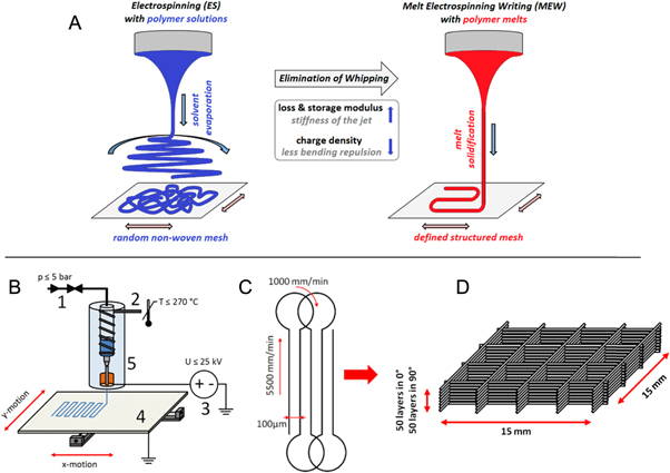
Figure 1. Schematic of electrospinning and experimental configuration. (A) The use of a polymer melt instead of a polymer solution leads to a stabilized jet and a controlled direct writing approach for fibre deposition. The MEW device (B) with (1) pneumatically assisted feeding system (2) electrical heating system (3) high voltage source (4) computer-aided movable collector plate (5) syringe with molten polymer and needle tip with electrode. (C) Diagram of G-code motion path (see supplementary data available from stacks.iop.org/BF/7/035002/mmedia) and deposition process of the filament-structure. (D) A deposition schematic of how the fifty sub-micron fibres are alternately deposited in each of the 0° and 90° directions.
Download figure:
Standard image High-resolution imageIn this study we investigate three key instrument parameters to melt electrospin smaller diameter fibres with control over filament deposition: high electrical field strengths, low flow rates and small diameter spinnerets [15, 18]. The filament morphology and composition of the sub-micron diameter filaments was analysed with scanning electron microscopy (SEM), atomic force microscopy (AFM), x-ray diffraction (XRD) and differential scanning calorimetry (DSC), revealing structural effects that occur during electrospinning such as the formation and orientation of crystalline regions. We also show that the fabricated structures can be processed with minimal damage in vitro when collecting onto a microscope slide coated with a reactive macromer.
2. Experimental methods
2.1. Materials
Poly--caprolactone (PCL) was purchased from Sigma-Aldrich Co. LLC and its molecular weight distribution analysed by SEC (detector: Jasco, RI 2031 plus/eluate: chloroform): Mn = 35 × 103 gmol−1/Mw = 83 × 103 gmol−1/Mz = 14 × 104 gmol−1/PDI = 2.4. The corresponding viscoelastic properties were measured with plate-to-plate (dp = 20 mm/distance lp = 1 mm) oscillating rheometry (MCR 301, Anton Paar, Ostfildern-Scharnhausen, Germany) with 20% deformation and 10 rad s−1 with increasing temperature from 80 °C up to 130 °C with 0.025 °C s−1.
2.2. MEW device
Figure 1(B) shows a schematic of a custom-built machine used to perform MEW in this study. It contains a high voltage source (DX250R, EMCO, Hallein, Austria) controlled by voltage divided measurement (Digit Multimeter 2100, Keithley, Cleveland, USA), a pneumatically regulated melt feeding system (regulator, FESTO, Berkheim, Germany) and a planar movable aluminum collector plate (XSlide, Velmex, New York, USA) triggered by G-code (MACH 3 CNC software, ARTSOFT, Livermore Falls, USA). The electrical heating system was proportional-integral-derivative-regulated (TR400, Delta-t, Bielefeld, Germany) to assure a stable melt temperature profile. Two advantages of MEW are that ventilation for the device is not required, nor is the removal of toxic solvents after fabrication [21, 25].
The instrument parameters were systematically investigated to achieve sub-micron filaments and deposited as boxes with minimal geometric deviations. The following parameters were varied: accelerating voltage (2.0–10.0 kV), collector distance (1–10 mm), heating temperature (80–120 °C), feeding air pressure (0.5–4.0 bar), spinneret diameters (21 G; 23 G; 25 G; 27 G; 30 G; 33 G) and axis velocity (1000–9000 mm min−1).
Box-structure scaffolds were melt electrospun by alternating layer deposition via 0° and 90° layers (15 × 15 mm2) with turning loops to optimize the deposition behaviour of the jet as shown in figure 1(C). The turning loops help with fibre placement and reduce structural defects near the edges. For SEM, DSC, XRD and in vitro research, 50 layers (100 fibres overlap at intersections) were deposited in each direction (0° and 90°) and the filament spacing was programmed to be 100 μm (figure 1(D)).
2.3. Instrumental analytics
The MEW box scaffolds were characterized with SEM (Supra 25, Zeiss, Oberkochen, Germany). For each sample, the filament diameter and mesh-widths in 0° and 90° direction were measured with n = 50, n = 100 respectively, after gold-sputtering. To observe surface roughness, AFM (FlexAFM, Nanosurf, Langen, Germany) measurements were performed five times with 5 μm in length on uncoated single filaments.
The crystallization behaviour of these ultrafine filaments was also investigated with XRD (D5005, Siemens, Berlin, Germany). To exclude diffraction effects induced by the lattice structure of the boxes, uniaxial aligned filaments were prepared with 100 μm filament spacing and analysed in Bragg–Brentano geometry, using Cu–Kα radiation (λ = 0.154 18 nm) with a voltage of 40 kV and a tube current of 40 mA. Scans were performed in a 2Θ range from 10 to 60° with a step size of 0.02° and a measuring time of 8 s per step. In addition to this, the uniaxial samples were irradiated at planar tilted angles (0°, 30°, 60°) to investigate a possible anisotropic crystallinity. Afterwards the sample was molten at 85 °C for 30 min and analysed in the same manner to assure constant experimental conditions. To investigate the validity of the results, an unaligned sample was prepared with lowered axis velocities (800 mm min−1) and measured three times.
Furthermore, the melting behaviour of the electrospun and raw material were characterized with DSC (204 F1 Phoenix, Netzsch, Selb, Germany). Therefore, similar masses (mmesh = 6.26 mg and mraw = 6.13 mg) were heated from −120 °C up to 90 °C twice and held for 5 min. Heating and cooling rates were performed with 10 K min−1 respectively −10 K min−1. As a control, DSC measurements with slow heating rates (2 K min−1) were performed. To investigate changes in morphology and quenching effects, additional filaments and box scaffolds were heat-treated at 55 °C (below the crystallization onset temperature) for 18 h and analysed with AFM, XRD and DSC.
2.4. Cell adhesion tests
Cell adhesion behaviour on MEW scaffolds was investigated using primary human mesenchymal stromal cells (hMSCs) from trabecular bone that were isolated from the femoral head of patients undergoing total hip arthroplasty [26]. HMSCs were cultivated in DMEM/Ham's F-12 + GlutaMAXTM-I medium supplemented with 10% fetal calf serum, 100 U ml−1 penicillin, 100 mg ml−1 streptomycin (all Gibco®, Life Technologies GmbH, Darmstadt, Germany) and 50 μg ml−1 L-ascorbic acid 2-phosphate (Sigma-Aldrich Chemie GmbH, Schnelldorf, Germany). HMSCs were seeded on the three different scaffold types at passage two at a density of 3.1 × 10⁴ cells cm−2 and incubated for 10 days in vitro (DIV) at 37 °C in a humidified atmosphere with 5% CO2. For in vitro experiments, MEW scaffolds with 50 layers of filaments and mesh-widths of 90 and 150 μm were deposited onto microscope slide coated with NCO-sP(EO-stat-PO) as described previously [27]. This coating is used to adhere the scaffold to the glass substrate as well as reducing protein adsorption on the surface [28, 29].
The constructs were fixed with 4 wt% paraformaldehyde, permeabilized with 0.2 vol% triton-X 100 and stained with phalloidin, tetramethylrhodamine B isothiocyanate (Sigma-Aldrich Chemie GmbH, Schnelldorf, Germany) and Hoechst 33342, trihydrochloride trihydrate (Molecular Probes, Life Technologies GmbH, Darmstadt, Germany) according to instructions. Inverse fluorescence microscopy using ApoTome and Z-stack function (Axio Observer.Z1 with ApoTome.2, Zeiss, Göttingen, Germany) and Zeiss software ZEN pro 2012 were used to obtain fluorescent images. Single pictures of optical sections of the Z-stacks were merged using ImageJ version 1.49 k.
3. Results and discussion
When electrospun, the electrified jets of high viscosity, low conductivity polymers can take a direct path to the collector [10, 11, 13, 15]. When arriving at a stationary collector, the viscoelastic jet buckles and coils due to mechanical forces, similar to that of non-electrified viscoelastic fluids [30–32]. Similarly, the movement of the collector can remove this buckling phenomenon and generate a straight filament, which in this case is solidified by cooling. This phenomenon can be visually observed.
3.1. MEW control
With its relatively broad molecular distribution (PDI = 2.4) and moderate molecular weight (Mw = 83 × 103 g mol−1) the PCL used in this study was readily melt electrospun. As would be expected of a molten linear polymer, the loss modulus G'' = 1.1 × 10⁴ Pa dominated the storage modulus G'' = 9.6 × 10² Pa at 84 °C. Numerous parameters investigated resulted in a regular frequency 'pulsing' that was a significant barrier to fabricate uniform structures (figure 2(A)). This filament pulsing varied in frequency of 0.1–0.01 Hz, often every minute. Care was needed to adjust the instrument parameter, to balance the forces (electrohydrodynamics; gravity, surface tension) and mass flow (air pressure, nozzle diameter) pulling and pushing the molten polymer through the spinneret [33]. Interestingly, SEM imaging of such pulsed samples revealed numerous nano-fibres with diameters below 100 nm (figure 2(B)). While these were a by-product of fibre pulsing, it is notable that such nano-fibres are possible using MEW. Hence, MEW does not only allow for precise morphology control, but may eventually be performed with much smaller polymer fibres.

Figure 2. Examples of (A)–(B) 'pulsing fibre' and (C)–(D) 'broken filaments'. Many instrument parameter combinations resulted in uneven jets due to differences in mass flow rate. Both thin (white arrow) and thick (black) fibres are produced. (B) Shows where a very fine fibre (red) is coiled near a much larger one. The red arrowed fibre had a diameter of 100 nm, and was coiled due to the higher critical translation speed required for small diameter fibres. (C) and (D) The height of the scaffold is greatest at the cross-section of filaments. Above a certain height, approximately 15–20 layers, defects in the scaffold may be seen (blue circle), where fibres have broken and leave a gap in the structure.
Download figure:
Standard image High-resolution imageAt the intersection of fibres, the height of the box scaffold is the greatest due to fibre overlaying. Structural breaks in the filaments can result and fibre sagging occurs increasingly with height (figure 2(C)). This could result in an incremental growing bending momentum and mainly tensile load acting on the fibres. Thus, breaks with increasing size were observed with a higher amount of deposited layers near fibre crossings, as is shown in figure 2(D). However such structural defects are influenced by the stored thermal energy of the solidifying fibres during MEW. When molten, these fibres can flow under a mechanical load and break—the ends are capped with 'droplets', circled blue in figure 2(D).
The smallest, highest quality diameter filaments were produced with the following parameters: accelerating voltage = 2.9 kV; collector distance = 1.5 mm; heating temperature = 109 °C (corresponding to a temperature of the spinneret = 84 °C); feeding air pressure = 2.8 bar; spinneret diameter = 33 G; velocity v = 5500 mm min−1. As a result of these dynamic balanced and constant instrument parameters highly defined structures were consistently fabricated. Due to the high precision and almost defect free morphology of the filament structures the centres of the resulting scaffolds are optically transparent, even with the stacking of 50 filaments (figure 3). Surrounding the transparent region is an opaque one—here the acceleration of the stage/fibre is still in progress and fibres are close together. Instead of straight-formed filaments, sinusoidal-formed fibres or lateral shifted piles were deposited within the opaque region. At the edge of the clear region are poorly spaced, yet accurately stacked filaments (figure 3(D)). Figure 3(E) also presents quantitative measurements using SEM for the top diameter fibres. The average upper-side filament diameter was 817 ± 165 nm after 50 layers in each direction (0° and 90°) of stacking, into box scaffolds with distances of 100.6 ± 5.1 μm. Figure 3(F) shows an overview of the uniform structured mesh, while figure 3(B) documents the exact stacking of the layer by layer controlled deposition process and allows a view on the ultrafine filaments. SEM images also show that the filament surface is smooth and homogeneous. The relatively small deviations in filament diameter indicated only low oscillation of dynamic process balance dominated by the electrical field (E = 1.9 kV mm−1). As shown by the SEM measurements, filament sagging occurred at the intersection of fibres since the height of the fibres here increased faster than the mid-point of each filament.

Figure 3. A scaffold morphology when manufactured with optimized instrument parameters. (A) The overview image shows a visibly clear centre of the scaffold, surrounded by a hazy zone. The circular loop helped both fibre alignment and acted as a frame for the structure. (B) Fibre walls that are 50 layers high could be fabricated. (C) The centre is well defined, however (D) shows how, after a turning loop, the acceleration of the collector movement pulls and slightly tilts the fibre and makes lateral shifts of deposited fibres. (E) and (F) SEM measurement of the fibre diameter box positioning in the well-defined middle zone.
Download figure:
Standard image High-resolution imageA consequence of aligned fibres, light scattering effects dominate uniform interaction between light and material in the middle range of the sample. When looking at the tilted samples, the filaments of the box structures induced the refraction of different wavelengths of the incident light (figure 4(A)), less towards the edges where they are less oriented. However large regions of uniform structures can be made from such sub-micron filaments. The breakage of filaments at larger stacking heights can still be seen in figure 4(C) and is a processing challenge to overcome in future studies with sub-micron filaments.
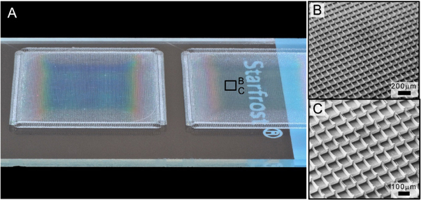
Figure 4. Box structured scaffolds printed upon a microscope slide, demonstrating the uniformity of the filament patterns. (A) Due to the high deposition accuracy on a glass slide there are optical effects when light is held in the background. (B) and (C) SEM images of such scaffolds tilted at 30° to show the regularity of the scaffold.
Download figure:
Standard image High-resolution image3.2. Morphological characterization
Assuming similar flow effects of molten polymers in melt spinning technologies, electrohydrodynamic jet stretching during solidification should orient polymer chains along the length of the filament [34, 35]. The resulting crystalline regions would then form perpendicular to the filament. This assumption could be confirmed through AFM analysis of single filaments (figures 5(A) and (B)). Due to the slight flow of molten polymer during and after deposition, an elliptic fit was set to analyse the shape. The integral of the filament indicates the cross section in order to compensate the inability of the AFM tip to measure spaces under overhangs. The cross section integral (2a = 1.3 μm/2b = 0.6 μm/A = 0.6 μm−2) of the deformed filament is equal to a circular filament of 850 nm in diameter.
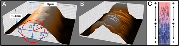
Figure 5. AFM analysis of single filaments deposited onto glass slides. (A) The fibres have a smooth surface directly after processing. (B) Due to the thermal aging slightly below the crystallization onset temperature, the formation of aligned lamellas could be observed. (C) A schematic of the electrified molten jet during the cooling phase, with polymer alignment along the length of the jet.
Download figure:
Standard image High-resolution imageIn agreement with SEM, AFM shows that the as-formed filaments showed a smooth surface with an average surface roughness of Ra = 23 ± 3 nm and a root mean square roughness of Rq = 28 ± 4 nm. In contrast to this, the surface roughness of single filaments changed significantly with Ra = 134 ± 36 nm/Rq = 153 ±31 nm due to annealing at 55 °C. At this temperature, the amorphous region flowed due to gravity, leaving the lamella clearly exposed, revealing information about the polymer solidification conditions and the macromolecular orientation. During the electrically induced acceleration of the jet, partially crystalline regions are forming via flow induced crystallization process [36, 37] and thereby increase the elastic modulus G'. A significant stretching of the electrified jet and anisotropic polymer chain orientation can be assumed during the process. This polymer alignment (figure 5(C)) and the inhibition of relaxation diffusion movement of macromolecules with further cooling and crystallization of the jet leads to an ordered structure of the lamellae.
For DSC measurements (figures 6(A) and (B)), the released specific thermal energy of the MEW structures ωmesh = 125 J g−1 was compared to the cut bulk PCL pellets. In contrast, the raw PCL material showed additional 30% higher specific melting energy ωraw = 171 J g−1. This result supports the assumption of quenched PCL filaments with incomplete crystallized and aligned regions combined with the influence of the high specific filament surface. Additionally, the melting onset Tmo and melting peak temperature Tmp of the electrospun material was 60.6, 70.2 °C respectively, and were shifted compared to the raw PCL with 55.5, 62.0 °C respectively. This could be the result of smaller sized crystalline areas enabled by high quenching rates, mainly at the high specific surface of the jet. All samples showed similar thermally properties during the 2nd heating cycle. Further, similarities between the 1st heating cycle and the 2nd heating cycles of the electrospun material were noticed. This shows an analogy of melting point and specific melting heat flow of the MEW processed material and PCL quenched with a rate of −10 K min−1.
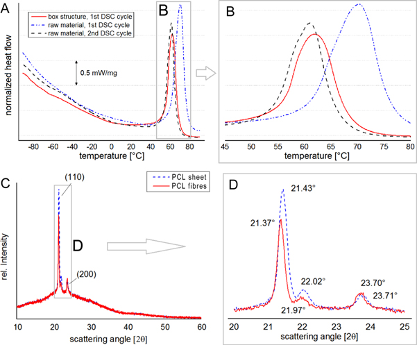
Figure 6. Morphology of the fibres with and without annealing. (A) and (B) DSC of the melting range for scaffold and the granulated raw PCL. The scaffold has lower released specific thermal energy compared to the raw PCL during the first heating cycle. For the second heating cycle, the melting points of MEW structure and the raw material were identical. (C) and (D) XRD diffraction patterns of filaments and sheets made from PCL. While the peak of the (200)-plane stayed constant during measurements, a shift and change in the integral peak area of the (110)-plains appeared.
Download figure:
Standard image High-resolution imageTo investigate an adverse effect of the fibrous morphology with difference in specific surface, additionally DSC measurements with slow heating rates (2 K min−1) were performed. These investigation yielded similar results with Tmo of 56.1, 59.8 °C respectively, and ωmesh = 148 J g−1, ωraw = 175 J g−1 respectively, for filaments and raw material. Equally to the melting temperature, the glass transition temperatures Tg of the electrospun material were measured at lowered values: −60.7 °C compared to the raw and aged materials (1st cycle raw PCL: −64.1 °C/2nd cycle raw PCL: −64.6 °C/2nd cycle mesh: −64.6 °C). This could be the result of quenching induced and mechanically stored energy, enabling increased molecular movement at lower temperatures.
XRD revealed a peak shift of the (110)-plains from the ultrafine filaments with 21.43° to the sheet material with 21.37° and from 22.02° to 21.97° (figures 6(C) and (D)). Further, the integral peak area as degree of the crystallinity was about 60% of the fibrous structures compared to the thermally treated analogue. This was most probably due to high quenching of the crystalline structure enabled by the high surface area of the electrified jet. In contrast to the changes of the (110)-plains the (200)-peaks showed similar behaviour in position and integral which further indicates an anisotropic influence of the MEW fabrication method and plastic deformation of the semi-crystalline PCL structure. Since the background intensity profile of both measurements was equivalent, possible geometric reasons for the different peak profiles of filaments and sheet could be excluded. This conclusion was verified by the testing of unaligned samples and the angle depending XRD-measurements of uniaxial samples, which confirmed the anisotropic crystallinity. In contrast to the 0° sample measured along the filaments (I = 1900 cps), the 30° and 60° tilted samples showed lowered (110) peak heights (I = 1200 cps, I = 1500 cps respectively). Additionally, due the heat treatment every sample showed a slight increase in peak height and integral which confirmed residual amorphous phases.
3.3. Scaffold handling for in vitro analysis
With handling such fine filament scaffolds in vitro, practical considerations such as maintaining structural integrity during washing phases is a key property. While larger filament scaffolds can be immersed directly into a well plate, the ultrafine fibres here are affected by mechanical forces due to changing liquids during culture and staining. We therefore used NCO-sP(EO-stat-PO)-coated microscope slide as collectors for fibre deposition and scaffold production [27, 29, 38] (figures 7(A) and (B)). While detachment was a big problem from untreated surfaces, the box scaffolds predominantly remained mechanically attached to the NCO-sP(EO-stat-PO) surface even for up to 10 DIV including media changes. Cell adhesion was directed to the scaffold rather than attaching to the NCO-sP(EO-stat-PO) surface (figures 7(C)–(F), allowing for proper fluorescence microscopy of cells adherent to the scaffolds only. Filaments remain primarily straight and were also stained blue by Hoechst labelling due to adsorption. The cells were able to bridge across the box pores, and could fill them with time (figure 7(F); supplementary information). We can therefore use such layered ultrafine filament scaffolds for future in vitro experiments and more detailed biochemical analysis without the risk of mixed cellular populations adhering to the scaffold or to the substrate, respectively.

Figure 7. Preparation and in vitro experiments with scaffolds. (A) Box structures with widths of 90 and 150 μm were directly deposited onto NCO-sP(EO-stat-PO)-coated glass slides, which are reactive and adhere the first fibre layer of the scaffold. (B) These macromers continue to react with water to form a passive surface. The scaffolds (with 50 stacked filaments at 90°) withstood frequent media changes and washing steps after 4 (C) and (D) and 10 (E) and (F) DIV. In this example, hMSCs preferred to adhere and grow along the filaments and tend not to adhere to the NCO-sP(EO-stat-PO) coated surface. Hoechst staining for nuclei also rendered the fibres blue.
Download figure:
Standard image High-resolution image
4. Conclusion
Uniform, sub-micron filaments (817 ± 165 nm) were stacked upon each other 50 times to produce a box scaffold (100.6 ± 5.1 μm) using MEW of a thermoplast. Homogeneity of the filament surface and the accurate filament deposition with sub-micrometer diameter allows defined scaffolds to be investigated for a number of applications including tissue engineering. Some defects such as pulsing and fibre breakage occurred, with the former eliminated by balancing the mass flow rate through the spinneret. The scaffolds can be handled in vitro with minimal damage using NCO-sP(EO-stat-PO)-coated microscope slides as a collector. The solvent-free additive manufacturing of such defined structures with ultrafine filaments at cellular dimensions is applicable to non-conductive melts. In this instance, the collector-substrates allowed long term cell culture without cell adhesion onto the glass substrate or scaffold detachment during media changes. It is envisioned that future applications of the sub-micron fibres described here is in combination with a larger structure, to produce a bimodal or multimodal scaffold with relevant volumes for tissue engineering.
Acknowledgments
This work was financially supported by the German Academic Exchange Service (DAAD, project No. 54417792) and the European research council (ERC consolidator grant Design2Heal, contract No. 617989). We would like to thank Björn Schulte from the Dept of Macromolecular Chemistry (RWTH-Aachen) for SEC analysis and Professor Dietmar W Hutmacher from Institute of Health and Biomedical Innovation (Queensland University of Technology) for his support of TDB for MEW device construction. There are no financial conflicts of interests for the authors and the research.