

Abstract
Gelatin methacrylate (GelMA) hydrogels have been widely used in tissue engineering because of their excellent biological and physical properties. Here, we used a microfluidic flow-focusing chip based on polymethyl methacrylate to fabricate cell-laden GelMA hydrogel microspheres. Structures of the throat region and photo crosslinking region on the chip, flow rate ratio of GelMA and oil phase, and GelMA concentration were optimized to obtain the stable and suitable size of microspheres. Cell-laden GelMA microspheres can be cryopreserved by slow freezing and rapid freezing. The survival rate of encapsulated cells after rapid freezing was significantly higher than that of unencapsulated cells. There was no significant difference between the results of the rapid freezing of encapsulated cells with 5% DMSO and the traditional slow freezing of suspended cells with 10% DMSO. It demonstrates the possibility that GelMA hydrogel itself can replace some of the cryoprotective agents and has some protective effect on cells. Our study provides new ideas to optimize GelMA hydrogels for cell cryopreservation, facilitating the off-the-shelf availability of tissue-engineered constructs.
Export citation and abstract BibTeX RIS
1. Introduction
Hydrogels are often used as artificial extracellular matrixes (ECMs) because of their unique properties similar to natural ECM, such as high water content, biocompatibility, degradability, and porosity [1]. Hydrogels that encapsulate cells can be used to create tissues in vitro for regenerative medicine applications and disease modeling [2, 3]. Hydrogel materials with spatiotemporally tunable mechanical properties have been employed to regulate cell behavior and direct cell fate [4]. Cell-laden hydrogel microspheres are made by encapsulating or entrapping cells within cross-linked hydrogel microspheres, which have great potential in tissue engineering and regenerative medicine, single-cell research, and tumor vaccinations [5]. The micrometer-sized spherical structure allows efficient diffusion of nutrients and oxygen into the cells [6]. In addition, microspheres can protect the encapsulated cells from immune rejection, making cell therapy more efficient [7]. Gelatin methacrylate (GelMA) hydrogel, is a product of gelatin modified with methacrylic anhydride. Owing to its excellent biocompatibility and photocrosslinking properties, GelMA is widely used in tissue engineering research [8–10]. Also, GelMA is tailorable, biodegradable, highly transparent, low immunogenic, and can promote cell adhesion and proliferation, which makes it a promising biomaterial [11, 12]. Cha et al [13] used GelMA microspheres as a cell culture platform, and generate injectable tissue constructs by culturing cardiac side population cells on their surface. Zhang et al [14] incorporated human platelet lysate into GelMA microspheres and effectively induced tubule formation of human umbilical cord endothelial cells as well as promoting the migration of human dental pulp stem cells (hDPSCs).
Conventional techniques for the preparation of hydrogel microspheres include bulk emulsification, electrohydrodynamic sptechniques Zhao et al [15]. However, the above methods have some shortcomings, such as non-uniform size distribution, low yield, and high consumption of material [16]. In comparison, microfluidic technology enables the preparation of uniformly sized hydrogel microspheres in rapid and large quantities [17]. Microfluidic chips can be fabricated using various methods (photolithography, molding, etching, 3D printing) to create micrometric structures. The main materials for chip production are inorganic materials (glass, silicon), polymers (PMMA, PDMS). The material properties, the geometric size and shape of microchannels, the properties of fluids, and the flow rate ratio all affect the preparation of microspheres on microfluidic chips [18]. Therefore, to obtain the ideal size and shape of microspheres, it is necessary to study hydrogel microsphere generation within microfluidic chips of specific materials.
Preparation of tissue engineering products constructed from cell-laden hydrogel microspheres is time-consuming, and is clinically inconvenient for patient care [19]. To enable clinical translation and commercialization of such structures [20], as well as to improve their off-the-shelf availability, it is necessary to store the cell-laden hydrogel microspheres effectively. Two cryopreservation methods are commonly used: slow freezing or vitrification. Yang et al [21] used 10% dimethyl sulfoxide (DMSO) as cryoprotective agents (CPA) to slow freeze the hDPSC-laden GelMA microspheres via Mr. Frosty freezing containers, the thawed cell survival rate was 79.56 ± 8.67%. Heng et al [22] found that a rapid cooling protocol with a high DMSO concentration (25%) for microencapsulated cells resulted in less than 10% cell viability after thawing. Slow freezing in 10% DMSO was utilized as a standard technique for cryopreservation of cells [23]. It allows water inside the cell to seep outside the cell, decreasing cell damage caused by intracellular ice. However, DMSO exhibited negative effects in laboratory and clinical applications [24]. With this in mind, there are continuous research on reducing the percentage of DMSO in CPAs. The existing cryopreservation protocols for cell-laden hydrogel microspheres are not uniform, and post-thaw cell survival rates are not high enough, making it difficult to meet the needs of clinical applications. Cryopreservation methods and mechanisms to achieve clinically available low concentrations of CPA for cell-laden GelMA microspheres have not been fully explored.
In this work, we fabricated fibroblasts-laden GelMA hydrogel microspheres and compared the effects of different cryopreservation methods on them. First, cell-laden GelMA microspheres were generated using PMMA microfluidic flow-focusing chips. The structure and fluid properties of the microfluidic chip (GelMA solution concentration, flow rate ratio of continuous and aqueous phases) were optimized to obtain suitable sizes of microspheres. Then, slow and rapid freezing methods are applied to the cryopreservation of GelMA hydrogel microspheres. The viability of the cells before and after cryopreservation was evaluated. Finally, cryomicroscopy studies were performed to investigate the ice formation/growth process during cooling and warming in GelMA hydrogel microspheres.
2. Materials and methods
2.1. Fabrication of microfluidic chip
The microfluidic chip is composed of four layers, including the cover layer (0.3 mm), the continuous phase flow layer (0.6 mm), the microsphere generation layer (0.6 mm), and the bottom layer (0.3 mm). The microdevice was designed with AutoCAD (Autodesk, USA), and etched in thick PMMA plates (Hengxin Acrylic Products Factory, China) using a CO2 laser engraving machine (VLS2.30, UNIVERSAL, USA). PMMA cover plate and bottom plate are pressed onto the surface of the double-sided tape, and the chip is bonded in a vacuum laminator (TBK-508, Shenzhen Wanda Technology Co, China).
2.2. Process platform
An overview of the microsphere fabrication platform is shown in figure 1. Aqueous GelMA solution (Yongqin quan Intelligent Equipment Co, China) and corn oil were selected as the dispersion and continuous phases, respectively. The flow rate of the two-phase fluid was regulated by a microfluidic pump. The GelMA solution and oil were pumped into the microfluidic chips at appropriate flow rates, respectively. The pump was connected to the microfluidic device using silicone microtubing capped with 23G needles. GelMA solution flew through a vertical channel of the chip, while the oil flew through two horizontal side channels. Two phases merged at the cross-section of the T-junction in the chip, to form microspheres which were then fully photo-crosslinked in the process of traveling in a long photocrosslinking zone on the chip. The hydrogel microspheres followed the flow of oil into a collection centrifuge tube containing the PBS solution. Bright-field images of GelMA microspheres were taken by an inverted bright-field microscope.
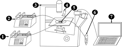
Figure 1. Schematic of microsphere fabrication platform. 1. GelMA phase pump 2. oil phase pump 3. microscope 4. 405 nm flashlight 5. microfluidic chip 6. centrifuge tube 7. computer.
Download figure:
Standard image High-resolution image2.3. Optimization of structure of the microfluidic chip
In order to disperse the aqueous phase effectively, an abrupt change called the throat is usually designed at the downstream of the T-junction, as shown in figure 2(A). The length and width of the throat structure were found to be critical in controlling microsphere diameter. To analyze the influence of throat size on the preparation of microspheres, three types of throat structures were designed: (1) 200 µm long and 100 µm wide, (2) 500 µm long and 250 µm wide, and (3) no throat, 500 µm wide. The flow rates of 5% GelMA solution and corn oil are 20 and 300 µl min−1, respectively. Microsphere generation was observed in real time by inverted bright-field microscopy, and the obtained GelMA hydrogel microspheres were analyzed for particle size by image acquisition software.

Figure 2. (A) Throat geometry in a flow-focusing microfluidic chip. L is the length of the throat structure, W is the width of the throat structure. (B) Chip with diamond photocrosslinking zone. (C) Chip with S-shaped photocrosslinking zone. (D). Schematic of generation of cell-laden GelMA microspheres.
Download figure:
Standard image High-resolution imageTo avoid fusion of the microspheres at the exit before crosslinking, the photocrosslinking region is integrated into the chip to achieve in-situ crosslinking of the GelMA microspheres in the chip. As depicted in figures 2(B) and (C), diamond and S-shaped photocrosslinking structures were designed. The diamond structure has a side length of 20 mm, and the S-shaped structure is formed by connecting six parallel rectangular channels with a length of 30 mm. The solidification of microspheres in the photocrosslinking zone was recorded with a cell phone.
2.4. Optimization of flow parameters on the microfluidic chip
The flow rate ratio and solution concentration have a direct impact on the generation of microspheres. In order to determine the flow parameters that would stabilize the formation of microspheres, different combinations of flow rate ratios (oil phase flow rate/GelMA solution flow rate) and GelMA solution concentrations were also examined. The following process parameters were kept constant during optimizing the flow parameters. The flow rate of GelMA solution is 20 µl min−1, throat dimensions are 200 µm long by 100 µm wide. The flow rate ratios were set as low (10), medium (15) and high (20), corresponding to oil phase flow rates of 200, 300 and 400 µl min−1. A wide range of GelMA concentrations (3%, 5%, 7%, and 10%) were also examined with low, medium, and high flow rate ratios to produce different microspheres. At each experiment, microsphere formation was visualized using an inverted microscope and a high-speed camera.
2.5. Generation of cell-laden GelMA microspheres
NIH 3T3 cells used in this study were provided by the Cell Bank of the Chinese Academy of Sciences. NIH 3T3 were cultured in a humidified incubator at 37 °C and 5% CO2 with DMEM medium supplemented with 10% fetal bovine serum and 1% penicillin-streptomycin in T75 flasks. After 90% confluence, these flasks were incubated with 0.25% Trypsin-EDTA for 3 min to detach the cells. Before encapsulation, GelMA solutions were sterile filtered and stored at 4 °C in centrifugal tubes wrapped with tin foil. The cell suspension was centrifuged at 1000 rpm for 5 min at room temperature, the supernatant was discarded, and cells were resuspended in GelMA solution containing 0.25% (w/v) Lithium phenyl-2,4,6-trimethylbenzoylphosphinate. The mixed cell-GelMA solutions were flown through the vertical channel of the PMMA chip while the oil phase was flown through the horizontal channels to form microsphere emulsions. As illustrated in figure 2(D), cell-laden GelMA solution and oil were transferred to 1 ml and 10 ml syringe, respectively, and then pumped into the microfluidic chips to generate cell-laden GelMA microspheres. The crosslinked cell-laden GelMA microspheres were separated and washed with PBS solution to remove excess oil, and then collected in petri dishes for further use.
To evaluate the effect of encapsulation on cells, GelMA lysis solution (Yongqin quan Intelligent Equipment Co., Ltd, China) was added to the cell-laden microspheres to release cells from the microspheres. The released cells were resuspended in culture medium for viability assays.
2.6. Cryopreservation of the cell-laden microspheres
For cryopreservation of cell-laden GelMA microspheres, slow freezing and rapid freezing are employed. The schematic diagram of different methods used for cryopreserving cell-laden microspheres is given in figure 3.
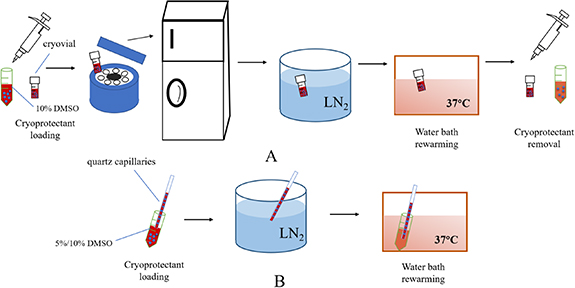
Figure 3. Experimental procedure diagram of different cryopreservation methods for cell-laden microspheres.(A: slow freezing; B: rapid freezing).
Download figure:
Standard image High-resolution imageFor slow freezing, the collected cell-laden microspheres were resuspended in 10% DMSO, and microspheres suspension was transferred into cryovials and was held at 4 °C for 10 min. Then, the cryovials was placed into frozen storage box and cooled down to −80 °C at −1 °C min−1 overnight. The cryovials were transferred into LN2 next day. The control group is unencapsulated NIH 3T3 cells, the freezing procedure was same as microencapsulated group.
For rapid freezing, cell-laden microspheres were incubated in 5% or 10% DMSO at 4 °C for 10 min, respectively. Then, the suspensions were loaded into high borosilicate glass capillaries (inner diameter 1 mm, wall thickness 0.3 mm) and plunged into liquid nitrogen. For rapid-freezing controls, unencapsulated NIH 3T3 cells were loaded in 10% DMSO at 4 °C for 10 min and then the cell suspension was added to the capillary and plunged directly into liquid nitrogen.
All resuscitation procedures were carried out by rapidly immersing the samples in a 37 °C water bath for rapid warming. Once warmed, the non-encapsulated cells or the cell-laden GelMA microsphere were incubated with DMEM at room temperature for 5 min. For the encapsulated group, the cells were released from the microcapsules by liquefying the GelMA hydrogel using GelMA lysis solution. After that, the cells were centrifuged at 1000 rpm for 5 min, and resuspended in culture medium for viability assays after removal of the supernatant.
The viability of the cells before and after cryopreservation was evaluated using 0.4% trypan blue solution. Live and dead cells were counted and cell viability was evaluated as the ratio of the number of live cells to the total number of cells. To quantify cell proliferation, the fresh and post-cryopreservation cells were seeded in 96-well plates for culturing. The cell number in each well was determined using the CCK-8 kit according to the instruction of the manufacturer. Proliferation capacity was assessed by the ratio of absorbance on day 2 and 3 to day 1.
2.7. Cryomicroscopic observation of GelMA microspheres
To investigate the ice formation/growth process of GelMA hydrogel microspheres during cooling and warming, cryomicroscopic studies were performed. A total of 3 µl sample (containing GelMA hydrogel microspheres and 10% DMSO) was loaded into the crucible and covered with a coverslip, then the crucible was moved to the cryo-stage chamber (BCS196, Linkam, UK). First, samples were cooled from 25 °C to −120 °C at 100 °C min−1 and equilibrated at −120 °C for 1 min. Then the samples were rewarmed to 25 °C at 100 °C min−1. Images of samples during the cooling and warming processes were recorded in real-time by a QImaging CCD.
2.8. Statistical analysis
The ANOVA test and Duncan's method were used to analyze the data for the variance and multiple comparisons, respectively. The value of p < 0.05 was considered significant.
3. Results
3.1. Optimization of the microfluidic chip structure
Microsphere formation in three types of throat structures were shown in figure 4. By changing the length and width of the throat, three sizes of GelMA hydrogel microspheres were generated with average diameters of 254.0, 343.5, and 487.6 µm, respectively. As the throat size increases, the average diameter and coefficient of variation of the generated microspheres increase. The formation of microspheres is difficult at T-junctions without a throat structure (figure 4(C)). It is generally considered that the diffusion of oxygen, nutrients, cellular products, and waste from the cells are better for microspheres with smaller diameters. Moreover, the particle size distribution of microspheres is more consistent. Therefore, we chose the microcapsules with a diameter of 254 µm in this study, corresponding to a throat structure of 200 µm long by 100 µm wide.

Figure 4. (A)–(C) Microsphere formation with different throat structures. (A): 200 µm long by 100 µm wide. (B): 500 µm long by 250 µm wide. (C): no throat, 500 µm wide. (D) Microsphere size distribution for different throat structures. Scale bar = 500 µm.
Download figure:
Standard image High-resolution imageFigure 5 shows the generation of hydrogel microspheres in different photocrosslinking structures. Because of the abrupt increase in the cross-sectional area of the diamond photocrosslinking zone, the fluid flow velocity decreases, resulting in collisions and fusion between the front and back microspheres. In contrast, the S-shaped photocrosslinking zone allows for uniform movement and in situ photocrosslinking of microspheres on the chip by designing rectangular channels with equal cross-sections. It is possible to control the crosslinking time of the microspheres to be about 15 s by controlling the number of rectangular channels to 6. The S-shaped structure was finally selected as the structure of the photocrosslinking region on the chip.

Figure 5. Photocrosslinking zone on the chip. A. diamond structure, B. S-shaped structure.
Download figure:
Standard image High-resolution image3.2. Optimization of flow parameters on the microfluidic chip
The flow patterns were expressed as the function of the flow rate ratio and GelMA solution concentration. As shown in figure 6, four types of flow patterns were observed in the T-junction including insufficient (a), dripping (b), jetting (c), and clogged microspheres (d).
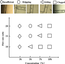
Figure 6. Flow pattern diagram as a function of the flow rate ratio and GelMA solution concentration. Optical images of four distinct flow patterns: (a) insufficient, (b) dripping, (c) jetting, and (d) clogged.
Download figure:
Standard image High-resolution image3% GelMA was insufficient to form microspheres, which could be attributed to microsphere fusion and rupture caused by the low concentration. At 5% GelMA, jet flow occurs at low flow ratios, increasing in microsphere size. Whereas, it can to form microspheres in a stable and repeatable manner at medium and high flow rate ratios. For 7% GelMA, unstable microspheres formed due to jetting were observed at all three flow ratios. In this case, lower flow rate ratios produce a larger volume of microspheres. For 10% GelMA, microspheres clog within the microfluidic channels, possibly due to greater viscosities that cannot be easily sheared into microspheres. Based on the above results, 5% GelMA, medium flow rate ratio (15), oil phase flow rate of 300 µl min−1, and GelMA solution flow rate of 20 µl min−1 were chosen to generate a cell-laden GelMA microsphere.
The cell distribution inside the cell-laden GelMA hydrogel microspheres generated with the optimized parameters is shown in figure 7. The cell-laden microspheres were lysed immediately after washing with PBS, and the survival rate for the released cells was 96.1%, which was not significantly different from the fresh group (97.0 ± 1.52%).
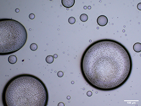
Figure 7. Optical microscopy image of the cell-laden GelMA hydrogel microspheres.
Download figure:
Standard image High-resolution image3.3. Cryopreservation of the cell-laden GelMA microspheres
Figure 8(A) shows the cell viability post-cryopreservation by different methods. The survival rates of unencapsulated cells and encapsulated cells after conventional slow freezing were 90.4 ± 3.71% and 91.1 ± 3.68%, respectively, which are not significant differences. The survival rates of encapsulated cells exposed to 5% and 10% DMSO after rapid freezing were 90.2 ± 4.92%, and 94.1 ± 4.87%, respectively. While the survival rate of unencapsulated cells in 10% DMSO after rapid freezing is only 45.4 ± 8.43%. It is interesting that the survival rate of unencapsulated cells after rapid freezing was significantly lower than that of encapsulated cells. However, the results of encapsulated cells loaded with 5% and 10% DMSO were similar after rapid freezing.
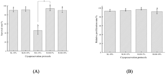
Figure 8. (A) cell viability and (B) proliferation of NIH 3T3 post cryopreservation under different conditions. SL-10%, slow freezing suspended cells in 10% DMSO. SLM-10%, slow freezing microencapsulated cells in 10% DMSO. RA-10%, rapid freezing suspended cells in 10% DMSO. RAM-5%, rapid freezing microencapsulated cells in 5% DMSO. RAM-10%, rapid freezing microencapsulated cells in 10% DMSO.
Download figure:
Standard image High-resolution imageTo further assess the long-term cell viability after cryopreservation, the proliferation of NIH 3T3 was studied post-cryopreservation. According to figure 8(B), the proliferation of unencapsulated cells (93.0 ± 0.37%) and encapsulated cells (94.3 ± 1.30%) after conventional slow freezing was not significant differences. It could also be seen that the proliferation efficiency of encapsulated cells loaded with 5% and 10% DMSO after rapid freezing was 96.8 ± 1.23% and 91.8 ± 4.91%, respectively. Rapid freezing of microencapsulated cells with low concentrations of CPA (5% DMSO) showed high viability and proliferation.
3.4. Crystalline properties of GelMA microspheres
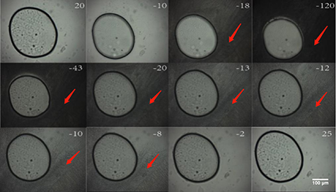
Images of ice crystals formed during cooling and warming are shown in figure 9. In 10% DMSO, ice crystals outside the microspheres formed at −18.3 °C (10% DMSO solution begins to darken at this temperature, the third picture on the first line in figure 9) during cooling and continued growing quickly. The melting of the ice crystal occurred at −43 °C (the darkness of 10% DMSO solution becomes lighter at this temperature, the first picture on the second line in figure 9) and finished at −2.2 °C. However, within the GelMA hydrogel microspheres, there was no visible ice crystal formation during cooling and warming. These observations suggest that the formation of ice crystals during cooling and warming was suppressed effectively by the GelMA hydrogel.
Figure 9. Typical images of GelMA hydrogel microspheres during the freezing and warming process. The numbers in the graph represent the temperature in °C.
Download figure:
Standard image High-resolution image
4. Discussion
In flow-focusing microchannels, the dispersed phase received shear forces from both sides of the continuous phase and therefore broke up into droplets. By modeling the GelMA solution as an incompressible Newtonian fluid flowing through a rectangular body, the maximum shear rate to the GelMA solution at the T-junction can be roughly calculated from  , where Q represents the flow rate and D is the equivalent length of the cross-section [25, 26]. The equivalent length was calculated from
  , where a and b are the sides of the channel. Reducing the throat size meant that the GelMA solution would be subjected to greater shear at the T-junction, resulting in a smaller droplet diameter. In addition, the S-shaped structure was found to be a more suitable photo-crosslinked structure for the generation of a cell-laden GelMA microsphere. Shelley et al found that when droplets can not move quickly enough downstream of the throat, they collided and fused [27]. Mohamed et al adopted a diamond-shaped crosslinking chamber design and set the flow rates of GelMA solution and mineral oil to 1.12 and 9–12 µl min−1, respectively, to prepare monodisperse and reliable droplets [28]. Here we used a larger flow rate but had difficulty in stabilizing the microspheres. This was most likely because the chip material we used was PMMA, such a flow rate ratio was still insufficient to disperse the droplets.
The capillary number ( ) has been commonly used to analyze the relative effects of viscous and capillary forces during droplet breakup [29], where
  is the viscosity,
  the velocity and
  the interfacial tension. Due to capillary Rayleigh-Plateau instability, the GelMA solution became unstable and droplets were formed [30]. In experiments to optimize the fluid properties, we observed that GelMA with low concentration was difficult to form spheres, whereas GelMA with high concentration clogged microchannels. Suvarnapathaki et al [25] certified that higher the concentration of GelMA solution possessed greater viscosity at the same shear force. As a result, the higher concentration GelMA solution was not easily sheared into droplets in time, and the jet phenomenon appeared. Because of the viscous force, the GelMA solution was not sheared in time at the throat, resulting in larger microspheres downstream. Takeuchi et al [31] found that the size of droplets in microchannels was a function of both the flow rate and the ratio of the two-phase flow rates. Our results suggested that stable monodisperse droplets can be generated only in a certain range of capillary numbers. A similar finding was made in a study by Park et al. They found that the number of capillaries that could form droplets was between 2.9 × 10⁻² and 2.0 × 10⁻¹ [32].
Cryopreservation of microencapsulated cells is a technology that facilitates the translation of tissue engineering constructs to the clinic. Our study investigated the potential of GelMA hydrogel encapsulation in cryopreservation. The viability of unencapsulated cells after slow freezing was significantly higher than that of fast freezing. Slow freezing is a process in which heat and mass transfer work together, which avoids the formation of ice crystals from intracellular water [33]. Vitrification allows the cells and the CPA to solidify into a glass state at a sufficiently rapid cooling rate without the formation of ice [34]. However, vitrification for conventional cell suspensions usually requires high concentrations of CPAs. 10% DMSO used for unencapsulated cells in this paper was too low to achieve vitrification [35]. Therefore, a significant amount of intracellular ice formed in unencapsulated cells during rapid freezing may be lethal to the cells [36]. In addition, we observed that the viability of cells after rapid freezing of GelMA microspheres with 5% and 10% DMSO was similar. Up to now, the most widely used osmotic CPA is DMSO [37]. However, the clinical use of DMSO is often questioned due to its toxicity leading to post-transplant complications [38]. For this reason, many researchers have worked to reduce the concentration of DMSO in CPAs during cryopreservation. Li et al [39] found that alginate microcapsules could reduce cell permeability damage induced by loading with DMSO by inhibiting cellular vesicles. We can speculate that for cells encapsulated in GelMA microspheres, the GelMA hydrogel shell acts as a diffusion barrier, effectively inhibiting the rapid increase in extracellular osmotic pressure. Therefore, for both 5% and 10% DMSO, the osmotic pressure difference across the cell membrane in GelMA microspheres is appropriate. Rapid freezing of cell-laden microspheres with 5% DMSO was not significantly different from the conventional slow freezing method, which means cell-laden GelMA hydrogel microspheres could reduce DMSO concentration effectively.
Fibroblasts released from GelMA microspheres had high cellular viability after both slow and rapid freezing. Vitrification is defined as no visible ice formation during cooling [40]. Combined with the results of low-temperature microscopy, it was clear that the microspheres may have been vitrified during rapid cooling. For rapid freezing, the survival rate of encapsulated cells was significantly higher than that of unencapsulated cells. It suggested that GelMA hydrogel could effectively reduce the ice crystal damage to cells during rapid freezing. The above results may be attributed to the following reasons. First, the GelMA hydrogel microsphere diameter shrunk from ∼274 µm to ∼190 µm as the temperature decreased. The reduction in volume accelerated the overall cooling of the GelMA hydrogel microspheres. In particular, hydrogel microspheres of relatively large size (300–400 µm) were reported to be particularly susceptible to cryogenic damage by ice crystal development [22]. The small-size GelMA microspheres obtained by optimizing the microfluidic device parameters in this paper are not easily affected by ice crystal development. Second, the DMSO solution crystallized before the GelMA hydrogel microspheres, causing water molecules in the microspheres to move toward the DMSO solution. Eventually, the GelMA hydrogel microspheres did not crystallize. According to some researchers, GelMA hydrogel can reduce the proportion of free water around the cells and the nucleation sites of ice crystals around the cells, while its 3D network porous structure will also limit ice crystal growth [41–43]. Therefore, GelMA hydrogels could protect the encapsulated cells during cooling.
5. Conclusions
In this work, we fabricated fibroblasts-laden GelMA hydrogel microspheres and provide a low CPA method for cryopreservation of 'ready-to-use' cell-biomaterial constructs. Rapid freezing of encapsulated cells with 5% DMSO is not significantly different from traditional slow freezing of suspended cells with 10% DMSO. Our study provides new ideas to optimize GelMA hydrogels for cell cryopreservation, facilitating the off-the-shelf availability of tissue-engineered constructs.
Data availability statement
All data that support the findings of this study are included within the article (and any supplementary files).