

Abstract
A major limitation of the 2D culture systems is that they fail to recapitulate the in vivo 3D cellular microenvironment whereby cell–cell and cell–extracellular matrix (ECM) interactions occur. In this paper, a biomaterial scaffold that mimics the structure of collagen fibers was produced by jet-spraying. This micro-fiber polycaprolactone (PCL) scaffold was evaluated for 3D culture of human bone marrow mesenchymal stromal cells (MSCs) in comparison with a commercially available electrospun scaffold. The jet-sprayed scaffolds had larger pore diameters, greater porosity, smaller diameter fibers, and more heterogeneous fiber diameter size distribution compared to the electrospun scaffolds. Cells on jet-sprayed constructs exhibited spread morphology with abundant cytoskeleton staining, whereas MSCs on electrospun scaffolds appeared less extended with fewer actin filaments. MSC proliferation and cell infiltration occurred at a faster rate on jet-sprayed compared to electrospun scaffolds. Osteogenic differentiation of MSCs and ECM production as measured by ALP, collagen and calcium deposition was superior on jet-sprayed compared to electrospun scaffolds. The jet-sprayed scaffold which mimics the native ECM and permits homogeneous cell infiltration is important for 3D in vitro applications such as bone cellular interaction studies or drug testing, as well as bone tissue engineering strategies.
Export citation and abstract BibTeX RIS

Content from this work may be used under the terms of the Creative Commons Attribution 3.0 licence. Any further distribution of this work must maintain attribution to the author(s) and the title of the work, journal citation and DOI.
1. Introduction
Bone cells in vivo reside in a 3D environment within an extracellular matrix (ECM) which acts as a structural and biochemical support. Nevertheless, conventional 2D monolayers of cells are used in vitro to investigate bone physiological and pathological cell processes, or to screen drug treatments or medical devices. A major limitation of the 2D culture systems is that they fail to recapitulate the in vivo 3D cellular microenvironment where cell–cell, cell–ECM interactions, as well as biochemical and mechanical signalling occur. In vivo animal models, in addition to being complex, expensive and posing ethical considerations, are not always predictive of clinical outcomes, due to differences with the human species [1]. Indeed, the attrition rate for new drug therapies after entering clinical development is approximately 90% despite the enormous investment (~1 billion dollars/drug) in development and screening [2, 3]. This failure is attributed to the inadequate 2D in vitro systems employed. It has been postulated that the missing link in drug discovery is 3D in vitro human cell culture [4]. It has been noted that cells in vitro 3D microenvironments represent their in vivo counterparts more accurately [5–7] by correctly regulating cell–cell and cell–ECM interactions [8, 9]. Further supporting evidence for the importance of 3D cultures for drug testing comes from several studies which demonstrate that drugs have dramatically different effects on cells when cultured in 3D compared to in 2D [10, 11].
To overcome the limitations of 2D cell culture there have been extensive efforts to produce 3D constructs that mimic the ECM of bone. Electrospinning is a technique that has received considerable attention as it can produce nanofiber scaffolds that closely resemble bone's native collagen ECM from synthetic biomaterials. Electrospun scaffolds can support cell adhesion [12–15], growth [13, 14], and osteogenic differentiation [14–16]. However, a major drawback of this technique is the lack of cell infiltration [12, 13, 17–19]. This is caused by inadequate pore size ensuing from the densely packed fiber layers. Furthermore, vascularisation of the scaffold and the supply of nutrients and removal of waste is inhibited, thereby restricting tissue in-growth in vivo [20]. Several strategies to increase porosity and cell infiltration of electrospun scaffolds have been investigated. The removal of sacrificial fibers only slightly increased cell penetration and dimensional instability occurred at higher sacrificial fiber content [17, 21]. Increased porosity and cellular infiltration was achieved by salt leaching [22, 23], but at the cost of macroscopic delaminations [22] and significantly reduced elastic modulus and yield stress [23]. Others showed dynamic culture facilitated infiltration of rat mesenchymal stromal cells (MSCs) into electrospun scaffolds [12, 15]. Cell electrospinning, a method which produces scaffolds composed of composite fibers encapsulating living cells [24, 25] has the potential to overcome the lack of cell infiltration into electrospun scaffolds. Cells were not harmed by the fabrication process, however upon submersion in growth medium the encapsulation of cells in the polymer threads was lost. The cells settled at the bottom of the well, while the polymer floated to the top of the medium, therefore the culture of these cells within the cell-electrospun scaffold was not possible [24, 25]. A further inherent disadvantage of conventional electrospinning is the limited scaffold thickness [26]. The polymer fibers are deposited on a grounded collector and since the polymer layers act as insulators, a loss of conductivity of the system occurs and thereby inhibits the thickness of electrospun scaffolds. Therefore, it is essential to explore alternative preparation techniques to construct biomaterial scaffolds that structurally emulate the native ECM of bone, while possessing sufficient porosity and thickness to permit cellular infiltration. Such a scaffold, in addition to its application as a 3D scaffold for in vitro screening of therapeutic drugs and investigations of cell functions in health and disease, would also be suitable for bone tissue engineering strategies. Recently there have been technologies developed to compete with the electrospinning technique. Arumuganathar et al developed coaxial aerodynamically assisted bio-threading (CAABT) which produces composite fibrous scaffolds by using differential pressure and this technique can incorporate cell-encapsulated micro threads [27, 28]. In addition, pressure-driven cell spinning (PDS) was developed which similarly to CAABT is driven by an applied pressure, but unlike CAABT it does not require a pressurized chamber [29, 30]. Furthermore, air jet-sprayed nanofiber 3D matrices have been developed and investigated for bone and vascular tissue engineering [31–34]. In contrast to the electrospinning technique which requires a costly high voltage source, air jet-spraying uses an airstream as the only driving power. Pressurized air causes polymer solutions to stretch into thin fibers at the outlet nozzle which can be collected on a substrate [31–34].
This paper presents a biomimetic micro-fiber polycaprolactone scaffold that was fabricated by using the jet-spraying technique. The objective of the study was to assess the potential of this scaffold for use as a 3D osteoinductive biomaterial scaffold. Specifically, the aim was to compare the attachment, proliferation, infiltration and osteoblastic differentiation of human bone marrow MSCs within these jet-sprayed scaffolds with a commercially available electrospun scaffold.
2. Materials and methods
2.1. Fabrication of micro-fiber PCL scaffolds
Polycaprolactone (PCL) mico-fiber scaffolds were fabricated by a proprietary jet-spraying process (Biomedical Tissues SAS, Nantes, France) by an adapted method similar to those previously published [31–33]. Briefly, PCL from Sigma Aldrich, with an average molecular weight of 80 000 g mol−1, was dissolved in chloroform (VWR, Fontenay-sous-Bois, France) to a concentration of 0.1 g mL−1. The solution was stirred at room temperature for 15 h at 400 rpm to ensure complete dissolution of PCL. This solution was sprayed through a nozzle using compressed air at 8 bars, at a distance of 40–50 cm from a collector grid. As chloroform evaporated, a polymer jet was produced and the fibers were collected. The production of the non-woven PCL membrane took approximately 13 min to achieve a thickness of 400 μm. The thickness of the membrane was determined by laser measurement (Keyence LK-G87; Keyence, Itasca, IL, USA) on a vacuum table. The micro-fiber PCL membrane was cut with a 22 mm diameter punch and deposited in each well of 12-well suspension culture plates (Greiner Bio-One, Courtaboeuf, France). A polycarbonate ring (machined by MPS France) secured the scaffold at the bottom of the well.
2.2. Electrospun scaffolds
Polylactic acid (PLA) scaffolds comprising discs 22 mm in diameter and 50 µm in thickness, were purchased from the Electrospinning company, Oxon, UK. They were supplied sterile in 12-well plates.
2.3. Characterization of scaffolds
The fiber diameter was measured from Scanning Electron Microscopy (SEM) images of the scaffolds. Samples were sputter-coated with gold and viewed with a Hitachi TM3000 SEM operating at an acceleration voltage of 5 kV and imaged at a magnification of 4000x. At least 7 images of randomly chosen fields, with at least 30 fibers in each image, were used for fiber measurements per scaffold. Fiber diameters were quantified by using the image processing program Image J (National Institutes of Health). A mercury intrusion porosimeter (Autopore IV, Micromeritics Instruments Corp, Norcross, USA) was used to characterize global porosity and the different pore sizes of the scaffolds. The samples were tested in the pressure range of 0–60 000 psi.
2.4. Isolation and characterisation of MSCs
Bone marrow (BM) aspirates were obtained from the iliac crest, by standard puncture and aspiration, of healthy human donors, after receiving informed consent according to the Declaration of Helsinki. Ethical approval was obtained from the Ethical Committee of Toulouse University. MSCs were expanded ex vivo in conventional plastic adhesion modality into cell stacks in basal culture medium consisting of α-MEM supplemented with 100 U mL−1 penicillin and 100 μg mL−1 streptomycin, 8% human platelet lysate (PLP) and 1 IU mL−1 medical grade heparin. PLP derived from authorized blood banks was used to avoid xenobiotic substances as we have shown previously that it can successfully support MSC expansion in vitro [35].
Flow cytometry was performed for phenotypic characterisation. Briefly, MSCs were suspended for 15 min in 100 μL phosphate buffered saline (PBS) and characterized by using the following antibodies: (a) CD90-FITC (clone 5E10), (b) CD73-PE (clone AD2), (c) CD105-FITC (clone 43A3), (d) CD34-PE (clone 4H11); (e) CD3-FITC (clone UCHT1). All antibodies were sourced from BioLegend through Ozyme (Paris, France), except CD73 which was sourced from BD Biosciences (Le Pont de Claix, France), and CD3 which was sourced from Beckman Coulter (Paris, France). MSC differentiation was induced towards osteogenic, adipogenic, or chondrogenic lineages by using Osteogenesis Differentiation Kit, StemPro Adipogenesis Differentiation Kit, or Chondrogenesis Differentiation Kit respectively (Gibco, Life Technologies, France) according to the manufacturers' instructions. Mineralization was detected by Alizarin red staining. For detection of adipogenic differentiation cells were stained with Oil Red O solution in 2-propanol, diluted to 60% using deionized water, while chondrogenic differentiation was detected by Alcian Blue staining.
2.5. Cell seeding on scaffolds
Jet-sprayed and electrospun scaffolds were soaked in ethanol for 1 h since both are hydrophobic. Following thorough washing with sterile PBS, scaffolds were incubated in basal culture media for 1 h. MSCs in passages 3–5 were plated onto the top of scaffolds in 12-well plates and into 12-well treated culture plastic plates as 2D controls. MSCs from three different healthy human donors were used in the current study for each experiment. Seeding density was 1 × 10⁵ cells per 3D scaffold and per 2D treated culture plastic well (26 000 cells cm−2). Seeded MSCs were cultured for 24 h in basal media, after which they were cultured with or without osteogenic supplements (250 μM ascorbic acid, 10 mM β-glycerolphosphate, and 100 nM dexamethasone) for up to 28 d.
2.6. Cell attachment and morphology
SEM was used to compare the attachment and morphology of cells on the jet-sprayed and electrospun polymer scaffolds. Specimens were rinsed with PBS, fixed in 4% paraformaldehyde, rinsed in PBS, and dehydrated in graded series of ethanol. After drying, specimens were mounted on aluminium stubs, sputter coated with gold, and viewed with a Hitachi TM3000 SEM (Hitachi, Tokyo, Japan) operating at an acceleration voltage of 5 kV. Cell size was measured from SEM images using Image J software. At least 20 images were analyzed at a magnification of x500 per scaffold type per time point. Cytoskeleton morphology was assessed by fluorescent staining. 3D cell/scaffold constructs and cell monolayers on 2D treated culture plastic were washed in PBS and fixed in 4% paraformaldehyde (PFA) for 20 min. Cell membranes were permeabilized with 0.1% Triton X-100 and 0.2% Tween in PBS for 15 min at 4 °C followed by incubation with 1% BSA and 5% goat serum in PBS at 37 °C to reduce non-specific background staining. The actin cytoskeleton of cells was stained with rhodamine phalloidin (Alexa Fluor® 488 Phalloidin, Invitrogen by Life Technologies, Saint Aubin, France) at a dilution of 1/40 with 1% BSA in PBS for 1 h at 37 °C in darkness. Cell were washed with 0.1% Triton X-100 and 0.2% Tween in PBS for 5 min, followed by nuclei staining with 4',6-Diamidino-2-Phenylindole, Dihydrochloride (DAPI) purchased from Molecular Probes by Life Technologies at a concentration of 1/40 000 for 10 min at room temperature in darkness. Images were captured using a Nikon A1R confocal laser-scanning microscope (Nikon, Amstelveen, The Netherlands).
2.7. Cell viability and cell number
Cell viability on scaffolds and plastic was evaluated at days 1, 7, 14 and 21 by staining live cells with the fluorescent stain Calcien AM (1.25 μL mL−1) and dead cells with Ethidium homodimer-1 (1 μL mL−1) according to the manufacturer's instructions (Invitrogen L-3224). Cells were viewed on a fluorescent microscope (HBO 50 Axiovert 40 CFL; Zeiss, Marly Le Roi, France).
To determine cell number at 1, 7, 14, 21 and 28 d of culture, cells on plastic and in scaffolds were lysed by using (1) 0.1% Triton x-100, 5mM Tris-HCL, pH 8, (2) three freeze/thaw cycles and (3) scaffolds/ cell monolayers were transferred to Eppendorf vials and sonicated for 20 min. The amount of double stranded DNA was measured in the supernatant of the solutions using a fluorescent Quant-iT™ PicoGreen® dsDNA reagent assay kit (Invitrogen) according to the manufacturer's instructions. A standard curve was created using serial dilutions of a known concentration of a lambda DNA solution. Fluorescent intensity was measured at 485 nm Excitation, 535 nm Emission on a microplate reader (Tristar LB 941; Berthold Technologies, Thoiry, France) and converted to ng of DNA.
2.8. Cell infiltration
At days 2, 7, 14, 21 and 28, scaffolds were embedded in cryomatrix (Neg 50, Thermoscientific), aided by using a vacuum dessicator attached to a pump (ELNOR). Cryomatrix embedded scaffolds were submerged in isopentane that was cooled in liquid nitrogen. Cryosections 18 μm thick were prepared using a cryostat (Micron HM560, Micron Microtech, France). To assess cellular infiltration, frozen sections were allowed to air-dry, fixed in 70% ethanol, stained with DAPI and analyzed using fluorescent microscopy (Leica DFC 300 FX).
2.9. Characterization of osteogenic differentiation and ECM production
2.9.1. Alkaline phosphatase (ALP) staining
Extracellular ALP was qualitatively evaluated by staining cells at days 7, 14 and 21 with Fast Violet B salt and Naphthol AS-MX phosphates alkaline solution. Cells were first fixed with a solution containing two volumes of citric acid-sodium citrate (1.5 mol L−1) to three volumes of acetone for 30 s at room temperature. Cells were then rinsed with deionized water and then incubated with a staining solution for 30 min in the dark. 50 mL of staining solution contains 48 mL of distilled water, 12 mg of Fast Violet B salt (F1631; Sigma Aldrich, Lyon, France) and 2 mL of Naphthol AS-MX phosphates alkaline solution (855; Sigma Aldrich).
2.9.2. Collagen production
At days 2, 7, 14, 21 and 28, collagen production was quantified by picro-sirus staining on polymer jet-sprayed and electron scaffolds as well as tissue culture plastic controls by using a previously published protocol [36]. Cells were fixed with 4% PFA in PBS for 15 min at room temperature. Scaffolds/wells were stained with 1 mL of picro-sirus red solution: 1 mg mL−1 sirus red (Sigma Aldrich) in saturated aqueous solution of picric acid (Sigma Aldrich) for 1 h on an orbital shaker. The unbound stained was removed by washing 4 times with deionized water. Images of the stained scaffolds/wells were taken for qualitative means and plates were stored at −20 °C. The bound stain was removed with 1 mL of 0.2 M NaOH: methanol (1 : 1) for 15 min on an orbital shaker. The optical density of the resulting solution was read at 450 nm on a plate reader (Tristar LB 941, Berthold Technologies). A standard curve was created by using known concentrations of sirus-red staining solution and collagen production was expressed as n moles/well.
2.9.3. Mineralization
Extracellular calcium was quantified on polymer jet-sprayed and electrospuns scaffolds as well as tissue culture plastic controls at 14, 21 and 28 d by alizarin red staining. Cells were fixed with 4% PFA in PBS for 15 min at room temperature. Scaffolds/wells were washed three times with dH2O prior to the addition of 1 mL of 40mM alizarin red solution (pH 4.1–4.3) for 20 min with gentle shaking. The unbound stain was removed with four dH2O washes. Images of the stained scaffolds/wells were taken for qualitative means and plates were stored at −20 °C. The alizarin red stain was quantified by adapting a previously published protocol [37]. The bound stain was dissolved by using 800 μL of 10% (v/v) of acetic acid under gentle agitation for 30 min. The polymer scaffolds and the monolayers on tissue culture plastic were transferred respectively to 1.5 mL micro-centrifuge tubes which were vortexed for 30 s each. Mineral oil (500 μL) was added to each tube and they were heated to 85 °C for 10 min, after which they were transferred to ice for 5 min. Once the tubes had cooled, the mineral oil was removed and the tubes were centrifuged at 15 000 g for 15 min. Then 500 μL of the supernatant was removed and transferred to new 1.5 mL micro-centrifuge tubes and 200 μL of ammonium hydroxide solution 10% (v/v) was added to neutralise the acid to achieve a pH of between 4.1–4.5. Aliquots of 150 μL of each samples were read in triplicate at an absorbance of 405 nm on a microplate reader (Tristar LB 941, Berthold Technologies). Standard curves were created by using serial dilution of known quantities of alizarin red stain. Mineralization results were expressed as μmoles of Calcium (Ca) per well since 1 mole of AR binds to 2 moles of Ca [38].
2.10. Statistics
MSCs were plated in triplicate (3 scaffolds) for each experiment and repeated for 3 different human donors (n = 3). Data are expressed as mean ± standard deviation (SD). Minitab statistical software was used (Minitab 16, UK) to perform a two-way analysis of variance (ANOVA) in order to determine statistical comparisons between groups. Statistical significance was set as p < 0.05.
3. Results
3.1. Smaller fiber diameter and higher porosity in jet-sprayed compared to electrospun scaffolds
The morphology of each scaffold at varying magnifications as observed by SEM is presented in figure 1(a). Both scaffolds contain fibers which are randomly orientated. It is evident that the jet-sprayed scaffold has larger variability in the diameter of its fibers compared to the electrospun scaffold. Figure 1(b) illustrates the log differential intrusion versus pore size of each scaffold type superimposed. The jet-sprayed scaffold had primarily three types of pores of 154, 8, and 2.5 μm, while the electrospun scaffold pores were 121, 25, and 7.4 μm in average diameter. Figure 1(c) shows the range of fiber diameters within the two types of scaffolds. The average fiber diameter was smaller in the jet-sprayed PCL scaffolds (0.73 ± 0.70 μm versus 1.92 ± 0.18 μm, p < 0.05) compared to the electrospun scaffold. The range of jet-sprayed fiber diameters was much larger than the range of the electrospun fibers; the maximum and minimum fiber diameters of the jet-sprayed scaffold was 5.37 and 0.09 μm respectively, and 2.44 and 1.40 μm respectively for the electrospun fibers. A summary of the geometrical features of each scaffold is presented in Table format in figure 1(d). Mercury intrusion porosimetry showed the total porosity of the jet-sprayed scaffold was 84.8% and for the electrospun scaffold it was 63.0%.

Figure 1. Scaffold characterization. (a) The morphology of jet-sprayed and electrospun scaffolds at varying magnifications as observed by SEM. (b) Mercury intrusion porosimetry results plotted as the log differential intrusion versus pore size of each scaffold type with each peak representing the different average pore sizes of the scaffolds. (c) The range of fiber diameters in each of the scaffold types with the outer bars representing the max and min values, while the horizontal line within each box represents the mean fiber diameter. At least 7 images at a magnification of × 4000, with at least 30 fibers in each image, were measured per scaffold. (d) Comparison of the geometrical features of jet-sprayed and electrospun scaffolds.
Download figure:
Standard image High-resolution image3.2. MSCs had a more spread morphology with more intense actin cytoskeleton staining on jet-sprayed compared to electrospun scaffolds
As depicted in Supplementary figure 1(a) MSCs displayed the classical MSC CD90+/CD73+/ CD105+/ CD34−/CD3− phenotype. In vitro differentiation potentials toward osteogenic, adipogenic, and chondrogenic lineages were observed after the histochemical staining by Alizarin Red, Oil red O, or Alcian blue respectively, supplementary figure 1(b).
The morphologies of MSCs attached to each of the jet-sprayed and electrospun scaffolds, as observed by SEM, are presented in figure 2(a). MSCs attached well to both scaffolds; MSCs on jet-sprayed scaffolds appeared to attach along the lengths of the fibers, whereas cells preferably attached to the electrospun scaffold via filopodia extensions of the cell membrane. Cells appear smaller on electrospun scaffolds, particularly at the least magnified view, compared to those on the jet-sprayed scaffold despite MSCs presented being from the same human donor. MSCs on jet-sprayed scaffolds assumed a more spread morphology compared to those attached to electrospun scaffolds which were more rounded. The size of cells attached to both types of scaffolds was quantified at 0.5 h and 1.5 h after plating by using Image J analysis of SEM images and is presented in figure 2(c). hMSCs on jet-sprayed scaffolds have a statistically significant larger surface area (expressed as μm2) compared to those on electrospun scaffolds at 0.5 h (295.58 ± 135.39 versus 230.21 ± 121.80, p < 0.05) and also at 1.5 h (715.65 ± 431.02 versus 388.03 ± 164.99, p < 0.05). Furthermore, hMSCs had a significantly larger area at 1.5 h compared to 0.5 h on both scaffold types. The cytoskeleton arrangement of the cells on both scaffold types and 2D plastic control as observed by confocal microscopy are presented in figure 2(b). On 2D plastic controls, the actin cytoskeleton of cells was primarily aligned in one direction and all cells were in focus of the z-plane shown. MSCs were orientated in different directions on the 3D jet-sprayed and electrospun scaffolds, with notably more intense cytoskeleton staining in cells on the jet-sprayed scaffold.
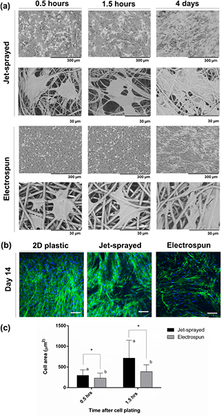
Figure 2. (a) Morphology of MSCs attached to jet-sprayed and electrospun scaffolds at 0.5 h, 1.5 h and 4 d as observed by SEM. Black scale bars represent 300 μm and 30 μm on the top and bottom rows as indicated. (b) Confocal microscopy of MSCs on 2D plastic, jet-sprayed and electrospun scaffolds 14 d after seeding cells. Actin cytoskeleton arrangement is shown in green by fluorescent staining with rhodamine phalloidin and nuclei are depicted in blue by DAPI staining. White scale bars represent 100 μm, n = 3 per scaffold type at each time point. (c) Cell surface area of hMSCs attached to jet-sprayed and electrospun scaffolds. * indicates statistical difference in cell size between scaffold types, while groups sharing a letter are also significantly different to one another, p < 0.05.
Download figure:
Standard image High-resolution image3.3. Higher MSC proliferation on jet-sprayed compared to electrospun scaffolds
MSCs were seeded onto 2D tissue culture plastic, jet-sprayed scaffolds and electrospun scaffolds, induced towards an osteogenic lineage for up to 28 d and cell number was assessed at each time point by using the pico-green assay for DNA quantification. As illustrated in figure 3(a), proliferation of MSCs progressed rapidly from days 1 to 7, largely plateaued thereafter, and cell viability was maintained up to 28 d of culture. The most striking observation was the statistically higher cell numbers on both control 2D treated culture plastic and jet-sprayed scaffolds compared to electrospun scaffolds. In figure 3(b), fluorescent staining depicted live cells in green and dead cells in red confirming that all three materials showed excellent biocompatibility and were capable of maintaining cell viability for the duration of the experiment.
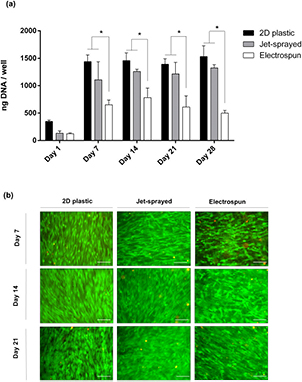
Figure 3. Proliferation and cell viability. (a) DNA content was quantified per well/scaffold by using the pico-green assay. Data from 3 different human donors (n = 3) plated in triplicate for each time point is presented, and shows proliferation of MSCs from days 1 to 28 cultured in osteogenic media, * indicates statistical differences (p < 0.05) between groups. (b) Fluorescent staining depicting live cells in green with the fluorescent Calcien AM stain and dead cells in red with ethidium homodimer-1 stain shows excellent biocompatibility of scaffolds at 7, 14 and 21 d.
Download figure:
Standard image High-resolution image3.4. Cell infiltration
Cell ingress into jet-sprayed and electrospun constructs was observed by DAPI stained cell nuclei in scaffold cross sections. As demonstrated in figure 4, MSCs penetrated through the entire depth of jet-sprayed scaffolds, even as early as day 2. By day 14 MSCs are homogeneously distributed throughout the scaffold cross section. Although a small portion of cells penetrated into the depth of the electrospun scaffold at days 2 and 7, MSCs remained largely as a monolayer on the surface of the electrospun scaffolds at day 7. By day 14 MSCs had infiltrated throughout the entire depth of the electrospun scaffold, and this was also observed at each time point up to 28.

Figure 4. MSC infiltration into jet-sprayed and electrospun micro-fiber scaffolds at days 2, 7, 14 and 28 as shown by fluorescent DAPI staining of cell nuclei in scaffold cryo-sections. 3 different human donors (n = 3) were plated in triplicate for each time point. White lines are drawn on the fluorescent images to show the periphery of each scaffold cross section. Scale bars are 200 μm and 100 μm in jet-sprayed and electrospun images respectively.
Download figure:
Standard image High-resolution image3.5. Synthesis of bone extracellular matrix by MSCs was higher on jet-sprayed compared to electrospun scaffolds
3.5.1. Alkaline phosphate production is enhanced on jet-sprayed scaffolds, even in the absence of osteogenic supplements
ALP activity was demonstrated qualitatively by staining ALP deposition. As illustrated in figure 5, MSCs cultured with (+OM) or without (−OM) osteogenic induction media were evaluated at days 7, 14 and 21. ALP production increased over the culture period as MSCs were induced towards the osteogenic lineage on all three materials. Staining appeared most intense on jet-sprayed scaffolds, compared to on 2D plastic and electrospun scaffolds. As expected, very minute quantities of ALP staining were observed on treated culture plastic and electrospun scaffolds when cells were cultured in basal proliferation media without osteogenic supplements. Interestingly, there was significant ALP staining on jet-sprayed scaffolds when cells were cultured without osteogenic induction media (−OM) and this was strikingly more intense compared to on 2D plastic or electrospun scaffolds, especially at day 7.

Figure 5. Alkaline phosphate deposition is shown qualitatively by Fast Violet B salt and Naphthol AS-MX phosphates alkaline staining of MSCs cultured with (+OM) or without (−OM) osteogenic induction media for 7, 14 and 21 d. 3 different human donors (n = 3) were plated in triplicate for each time point. Black scale bar represents 5.5 mm.
Download figure:
Standard image High-resolution image3.5.2. Collagen production per MSC was similar on jet-sprayed and electrospun scaffolds and both were higher compared to 2D plastic
Collagen production by MSCs cultured on tissue culture plastic, jet-sprayed scaffolds, or electrospun scaffolds was detected by sirus red staining. When the stain was solubilised and quantified per scaffold as shown in figure 6(a), there was significantly more collagen production on jet-sprayed scaffolds compared to both 2D plastic and electrospun scaffolds at all time points (p < 0.05). At day 28, there was significantly less collagen production on electrospun scaffolds compared to 2D plastic, p < 0.05. However, when collagen production was normalized to DNA quantity, as depicted in figure 6(b), cells on jet-sprayed and electrospun scaffolds produced the same quantity of collagen, with both scaffolds inducing significantly higher collagen production compared to 2D tissue culture plastic.

Figure 6. Collagen production. Collagen was stained with sirus red and the bound stain was solubilized and quantified. Data from 3 different human donors (n = 3) plated in triplicate for each time point and cultured in osteogenic media are presented. (a) Collagen production by MSCs at day 7, 14, 21 and 28 is presented per well/scaffold. (b) Collagen production was normalized to DNA content, * indicates statistical differences (p < 0.05) between groups.
Download figure:
Standard image High-resolution image3.5.3. Calcium production was higher on jet-sprayed compared to electrospun scaffolds
Calcium deposition was qualitatively assessed by alizarin red staining as depicted in figure 7(a), while figures 7(b) and (c) illustrate quantitative data attained from solubilising alizarin red staining. When mineralization was induced with osteogenic induction media, calcium deposition increased from day 14 to day 28 in all groups. When calcium was enumerated per scaffold, as depicted in figure 7(b), there was significantly higher calcium present on jet-sprayed scaffolds compared to electrospun scaffolds at days 14, 21 and 28 (p < 0.05), and compared to 2D tissue culture plastic at days 14 and 28 (p < 0.05). Figure 7(c) demonstrated calcium deposition when normalized to DNA quantity and shows significantly more calcium per DNA content on jet-sprayed scaffolds compared to electrospun scaffolds at day 14, and compared to 2D tissue culture plastic at days 14 and 28 (p < 0.05). There was a trend towards increased calcium deposition on electrospun scaffolds compared to 2D plastic at each time point; however this did not reach statistical significance.

Figure 7. Calcium deposition. (a) MSCs were cultured with (+OM) or without (−OM) osteogenic induction media for 14, 21 and 28 d. Mineralization was qualitatively assessed by alizarin red staining and representative images from each of the 2D plastic, jet-sprayed and electrospun scaffolds are presented. Scale bar represents 5.5 mm. (b) Histogram represents quantitative data from 3 human donors (n = 3) plated in triplicate for each time point when the stain was solubilised and enumerated per well/scaffold. (c) shows calcium deposition normalized to DNA content, * indicates statistical differences (p < 0.05) between groups.
Download figure:
Standard image High-resolution image
4. Discussion
In creating 3D scaffolds for cells, it is preferable to present cells with an environment which closely resembles their native ECM. Electrospinning is the most widely employed technique for the construction of micro-fiber scaffolds since there is abundant evidence of its ability to produce biocompatible, biomimetic scaffolds capable of supporting cell growth. However, the lack of cellular infiltration and limited scaffold thickness are major drawbacks of the electrospinning technique which limits its use in 3D in vitro models or in tissue engineering applications. In this study, micro-fiber scaffolds which were prepared by a jet-spraying technique were compared to electrospun scaffolds for MSC in vitro 3D culture whereas the 2D treated culture plastic served as a control substrate. MSCs on jet-sprayed scaffolds were more spread, with more intense actin cytoskeleton staining, and faster proliferation and infiltration rates compared to cells on electrospun scaffolds. In terms of osteogenic differentiation and ECM production, while both scaffolds induced similar quantities of collagen production, ALP and calcium production were higher on jet-sprayed scaffolds compared to electrospun scaffolds.
Jet-sprayed and electrospun scaffolds demonstrated significantly different architectures. Notably, the jet-sprayed scaffolds had greater porosity, larger pore diameters, smaller diameter fibers, and more heterogeneous fiber diameter size distribution compared to the electrospun scaffolds. Electrospinning uses a high voltage for spinning fibers that are deposited on a metal grounded collector. As most polymers are insulating materials, the electrospinning method produces only thin membranes as the system loses conductivity. Unlike electrospinning, the thickness of jet-sprayed scaffolds is not dictated or limited by an electric field. Rather, the jet spraying process allows the formation of several polymers into thick non-woven 3D scaffolds of various shapes by using compressed air. Materials that have been utilized to fabricate micro-fibrous scaffolds using the jet-spraying technique to date include PCL, presented in the current study and by others [31–33], as well as hydroxyapatite/ PLA [33], and nylon [34]. This technique can fabricate scaffolds up to a thickness of 10 mm. The resulting 3D scaffolds have high porosity with a wide range of fiber diameter having similar sizes as collagen fibers, unlike the electrospun scaffolds which have a narrow size distribution and lower porosity. These structural differences may explain the observed biological responses in the current study.
MSCs are anchorage dependent cells and they appear to attach along the lengths of the thinnest fibers in the jet-sprayed scaffold whereas they attach to the electrospun scaffold by extending filopodia to the micro-fibers. Focal adhesions are the foremost locations of actin filament attachment to the ECM. The exact scaffold features responsible for the differences in cell attachment, morphology and cytoskeleton tension are unknown, however these factors are all connected since it has been shown that cell shape directly controls focal adhesion assembly [39] and depends on the actin cytoskeleton [40].
Both scaffolds demonstrated biocompatibility as cell viability was maintained for the duration of the experiment. The proliferative rate of cells was higher on the jet-sprayed scaffolds compared to electrospun scaffolds and the differences in cell morphology between these scaffolds may be a contributing factor since cell shape governs proliferation [41]. Cell infiltration occurred at a faster rate in jet-sprayed compared to electrospun scaffolds, most likely due to the larger pore diameter and higher porosity of the jet-sprayed scaffolds. However, it must be noted that the electrospun scaffolds did show homogeneous distribution of cells within the scaffold by day 14, and cell penetration, although very limited, was noted at days 2 and 7. This observation is in contrast to many studies showing complete lack of cellular infiltration into statically cultured electrospun scaffolds [17, 19]. A possible contributing factor for this discrepancy could be the cell culture media used; in the current study α-MEM with 8% PLP was used, which in our hands produces smaller cells than when they are cultured in DMEM with FBS, which was often used in previous cell infiltration studies [17, 19].
It must be noted that the current study has some limitations. Firstly, the fittings which secured the electrospun scaffolds in the 12-well plates were quite loose and hence allowed some cells to pass beneath to the bottom of the well. Since this did not occur with the tight jet-sprayed scaffold fittings, different plating densities onto the top side of the scaffolds may have occurred. Furthermore, the jet-sprayed scaffolds had a greater thickness (400 μm) compared to the electrospun scaffolds (50 μm), therefore cells had more space to proliferate into the depths of the jet-sprayed scaffolds and had a greater surface area available. It was previously demonstrated that thicker scaffolds provide a better substrate for cell proliferation [42]. Nevertheless, it is highly improbable that either limitation affected results since a) cells largely remained on the top surface of the electrospun scaffolds until after day 7 in spite of amply space remaining in the depth of the scaffold and b) all quantitative measurements were expressed per quantity of DNA.
The osteogenic differentiation of MSCs is controlled by several cues in their local microenvironment. In this study, MSCs on both scaffolds were chemically induced towards the osteogenic lineage by using the same concentrations of standard soluble factors. Despite this, there was significantly higher calcium production per cell on jet-sprayed compared to electrospun scaffolds and extracellular ALP staining was even observed in the absence of osteogenic supplements on jet-sprayed scaffolds. The underlying causes have not been explored, however we hypothesis that it may be related to the difference in the shape of MSCs attached to each scaffold. As noted, cells on jet-sprayed scaffolds appeared more spread and exhibited more actin stress fibers compared to the cells on the electrospun scaffolds. McBeath et al demonstrated that cell shape drives MSC lineage commitment, identifying a spread cell shape as a key regulator of osteoblast differentiation. This shape-dependent control of osteoblast lineage commitment was caused by elevated RhoA activity and ROCK-mediated cytoskeleton tension of spread cells [43]. The topographical surface features of the jet-sprayed scaffolds may also be more favourable than those of the electrospun scaffolds in terms of osteoblast lineage commitment since surface topography has been shown to alter the osteogenic differentiation of MSCs [44, 45]. We believe that the variance in cell spreading between scaffolds was due to the scaffold architectures rather than their constituent materials. Osteoblasts remain rounded on films of PCL and PLA 1.5 h after plating [46], while we observed spreading after just 30 min in the current study. In addition, 4 h after plating, cells on PLA films were more spread compared to those on PCL films [46], the opposite to what we observed on the fiber scaffolds in the current study. Together, this indicates a structural influence on cell morphology. Indeed a recent study showed that the diameter of fibers in nanostructured polymer scaffolds influences osteogenic differentiation of pre-osteoblast cells [47]. The observation of ALP staining but no calcium deposition without the addition of soluble osteogenic induction factors may be explained by ALP being an early osteogenic differentiation marker, whereas calcium deposition occurs at a much later differentiation stage. Both scaffolds show significantly increased osteogenesis compared to 2D tissue culture plastic. This finding is in agreement with a previous study which showed enhanced osteogenic differentiation on nanofiber substrates compared to smooth substrates [16].
2D monolayer cell culture systems are inadequate for investigating physiological and pathological cell activities and drug screening since they fail to accurately mimic the 3D in vivo cellular environment. 3D in vitro culture systems could overcome these limitations and offer advantages over animal models. Adequate and rapid cell ingress into synthetic micro-fiber scaffolds is vital in vitro to better recapitulate the in vivo 3D cellular environment and resemble the native ECM. Such a 3D model provided by using jet-sprayed scaffolds would present a more appropriate method for drug screening compared to electrospun scaffolds currently employed for therapeutic drug analysis which were noted to be limited by inadequate cellular infiltration [10]. A scaffold which mimics the native ECM while permitting homogeneous cell infiltration is important for tissue engineering applications to allow the penetration of host cells and vasculature, enrich diffusion of nutrients and waste products and enhance integration into the host tissue.
5. Conclusions
In this study, micro-fiber polymer scaffolds fabricated by either jet-spraying or electrospinning were compared for in vitro growth and osteogenic differentiation of MSCs. Cells on jet-sprayed scaffolds exhibited a more spread morphology, more intense actin cytoskeleton staining, higher growth rate, and enhanced cellular infiltration compared to MSCs on electrospun scaffolds. Osteogenic differentiation of MSCs and ECM production as measured by ALP and calcium deposition was superior on jet-sprayed compared to electrospun scaffolds. The jet-sprayed scaffold which mimics the native ECM and permits homogeneous cell infiltration is important for 3D in vitro applications such as bone cellular interaction studies or drug testing, as well as bone tissue engineering strategies.
Acknowledgments
The authors would like to acknowledge funding from Region Pays de la Loire: Postdoctoral Fellowship and the European Commission under the FP7 framework, Reborne Project (#241879). We would also like to thank EFS Toulouse for kindly providing the MSCs.
Disclosures
Pierre Layrolle is founder of the spin-off company Biomedical Tissues that produces the jet-sprayed PCL micro-fiber scaffolds. Cyril D'Arros was an employee of Biomedical Tissues. The other authors state they have no conflict of interest.