
Abstract
This paper presents a novel approach for designing a freeform bending-resistant structure from the combination of explicit discrete component-based topology optimization (TO) and the porcupine quill-inspired features. To embed the porcupine quill's features into the TO formulations, the method involves constructing discrete components at various scales to imitate features including solid shell, stochastically distributed pores, and graded stiffeners. The components are iteratively updated, and the optimization process allows for the grading of quill-inspired features while achieving optimal structural compliance under bending loads. The proposed approach is demonstrated to be effective through the resolution of Messershmitt–Bolkow–Blohm (MBB) beam designs, parameterized studies of geometric parameters, and numerical validation of long-span and short-span quill-inspired beam designs. By examining the von Mises stress distribution, the study highlights the mitigation of material yielding at the shell region brought by the geometric features of porcupine quills, leading to the potential theory support for the bending resistance. The optimized MBB beams are manufactured using the material extrusion technique, and three-point bending tests are conducted to explore the failure mitigation capability of the quill-inspired beam under large deformation. Consequently, the study concludes that the proposed quill-inspired component-based TO approach can design a structure with excellent bending resistance according to the improved energy absorption as well as increased deformation after reaching 75% peak load.
Export citation and abstract BibTeX RIS

Original content from this work may be used under the terms of the Creative Commons Attribution 4.0 license. Any further distribution of this work must maintain attribution to the author(s) and the title of the work, journal citation and DOI.
1. Introduction
The progress in additive manufacturing technology provides the feasibility of developing structures with complex geometric features as well as the rapid development of relevant design techniques. Under this circumstance, many works have been conducted to improve flexural performance in innovative sandwich beam structure designs by applying topology optimization (TO) algorithms or cellular structures [1–4]. In addition to designing cores composed of honeycomb structures [5–8], auxetic structures [9–11], and lattice structures [2, 4, 12], learning from biological structure such as Cybister beetles [13], glass sponges [14], and dactyl's club [15] is another effective tool to develop novel infilling patterns of the beam design. Among these bio-inspiration resources, porcupine quill, which is composed of a stiff shell and foamy infillings, is regarded as an outstanding candidate for beam design due to its superior strength and buckling resistance [16, 17].
Many studies have been conducted to explore the mechanical performance of porcupine quills. Yang et al [18] have conducted compression tests on porcupine quills, concluding that the large deformation of the quill's foam core can mitigate the buckling of the stiff shell. Chou and Overfelt [19] have conducted tensile tests on quills from new-world porcupines, illustrating that the shell region contributes to the main load-bearing capacity of quill under tension. Torres et al [20] have conducted a failure analysis of quills under compression, proving that the energy dissipation provided by the foam core can avoid abrupt failure once buckling occurs. The foam-like features have also been proven to have excellent capability of failure resistance. To utilize the attractive performance properties, novel modelling techniques have been investigated to facilitate the bio-mimicking of the porcupine quill's microstructure. With the feature characterization via x-ray micro-computed tomography techniques [21], Tee et al [22] have utilized Voronoi seeds to generate a truss-based network, leading to the design of a manufacturable stochastic quill-inspired tube.
Although the current research in the modelling of porcupine quills' features has successfully captured rich information from the microstructure, most of the modelling techniques are based on the heuristic design strategy. The geometric features such as shell thickness, pore size, and distribution of pores cannot be directly related to the flexural performance, causing the ambiguity in simultaneously tailoring both the structural shape and the porous network to further utilize the structural excellence of porcupine quill. Furthermore, the quill-inspired features have mainly been applied to structural designs in regular shapes (e.g. foam-infilled tubes). The constrained designability of porcupine quill-inspired structure thus presents significant challenges when the flexible structural boundary (i.e. freeform design) is demanded in specific design tasks. Therefore, the development of a freeform porcupine quill-inspired structure design methodology that can directly relate the manipulation of geometric features to flexural performance should be considered.
One possible solution is to modify the moving morphable component-based (MMC-based) TO algorithm by embedding the porcupine quills' features into its explicit geometric primitives. Originating from the 2D moving morphable components algorithm proposed by Guo et al [23], MMC-based TO approaches, which manipulate the explicit geometric primitives as minimal control units, can be utilized to generate freeform structures with the conservation of specific geometric features under customized loading conditions, constraints, and design objectives. Starting from the 2D rectangular components with straight edges [23], the implementation of linearly varying and quadratically varying cross-sectional thickness along the curved centreline has been facilitated to enhance the capability of components in geometric representation [24]. To generate components with smooth boundaries, B-spline curves [25], Bezier curves [26], and non-uniform rational B-spline curves [27] are embedded into the TO formulations.
TO approaches have been extended to design structures with solid shells and porous infillings [28–33]. For implicit level-set TO approaches [31–33], the solid shell is implemented by setting up a constant offset value to the structure boundary, where the infillings are composed of multi-material or truss-based connectable lattices. MMC-based TO approaches can tackle the varying thickness requirement by explicitly manipulating the thickness of each component both in 2D [28, 31] and 3D [34–37] problems. For the design of infillings, the truss-based lattices are composed of bar components at the micro level in the adaptive component-based approach proposed by Hoang et al [28]. Adaptive component-based approaches can design porous structures with organic boundary shapes, where bar components with round ends at the micro level are optimized within a non-design boundary [29]. To generate stochastic distributed porous infillings, 3D sphere components are utilized to optimize infillings in the bar sphere approach proposed by Lan et al [30].
For embedding porcupine quill's features into TO approaches, two factors are demanded to be considered when designing components. Firstly, the shape representation should be efficient to capture the porcupine quill's features including a solid shell with varying thickness as well as foamy infillings that contain both regular and irregular shapes of pores. Secondly, the proposed method should provide the potential to control the complexity of the structure so that feasible fabrication can be achieved when different fabrication techniques are considered. Currently, the coated structures generated by the implicit level-set TO approach are limited to shells with constant thickness and infillings in truss-based patterns, leading to insufficient flexibility for suitable mimicking of the porcupine quill's structure.
Although the MMC-based TO approach can concurrently optimize the shell with varying thickness and the non-uniform porous infillings. Compared to components with curved features, simple components such as bars with round ends and spheres, which have less flexibility but sufficient capability of constructing porous nested structures, are easier for the investigation of influence brought by porcupine quills' features. However, the infillings generated by the adaptive component-based approach are limited to a predefined truss frame, where the stochastic distribution of pores observed in the porcupine quill's nested structure cannot be captured well. For the bar sphere approach, the stochastic distribution of pores can be achieved by merging of sphere components. However, the bar sphere approach can only support a combination of struts in the structure at the macro level, where the organic boundary observed in the porcupine quill's structure cannot be facilitated.
In this work, a novel MMC-based TO design scheme with the embedding of quill-inspired features is proposed to provide a way of optimizing the flexural stiffness of freeform foam-like beams with admissible fail-safe functionalities. With a group of bar and circular components, a solid shell with a foamy core is constructed to mimic the main features observed in porcupine quills' structure. By manipulating the design range of multiple design variables that represent bar and circular components, the proposed method can achieve varying shell thickness, pore size, boundary shape, and distribution of pores in beam designs. These parametric studies can support the more efficient porcupine quill-inspired beam design in the future. In addition, the representation of porous networks via circular components and the radius control in bar components provided by the proposed method contribute to advantages such as organic structure boundary shape, controllable stochastic distribution of pores, and adjustable manufacturability. Based on the proposed approach, bio-mimicking structure designs can be facilitated with numerical guidance rather than only with heuristic inspiration. From the inspiration of the proposed method, the MMC-based TO approach can serve as a systematic way of designing freeform bio-inspired structures under numerical guidance.
The content of this project is started by illustrating the construction of components that can capture the porcupine quill's features. In section 3, the optimization problem settings and the sensitivity analysis for explicit design variables are developed. In section 4, multiple cases including long-span beam, short-span beam, and Messershmitt–Bolkow–Blohm (MBB) beam are illustrated to show the broad applications of the proposed approach. The von Mises stress distribution of the topology-optimized structure is investigated to reveal the mechanism of fail-safe functionalities due to the existence of quill-inspired features. In addition, the three-point bending test is conducted on the optimized MBB beams fabricated by the material extrusion (MEX) method to validate the failure mitigation capability of the quill-inspired structure. In section 5, the findings of this project are summarized and highlighted for the future guidance of porcupine quill-inspired design.
2. Construction of quill-inspired components
To conduct the evaluation of structural performance and the sensitivity analysis, the parameterized geometric components need to be processed by extending the density-based approach. The process of the explicit component-based TO method is shown in figure 1. Firstly, the quill-inspired components are constructed and parameterized based on the simplification of the quill's hierarchical structure in nature. As the preparation step for the generation of density maps, the minimum distance fields, which represent the minimal interval between the component's boundary and each element, are calculated iteratively for each component. By utilizing the distance field value as the input, the density of each element is then obtained with the projection function. Boolean operations are conducted to express the structure design at the current iteration. The finite element analysis is applied to obtain structural performance, which is structural compliance in this work. With the combination of the adjoint method, the sensitivities are derived. The generation of geometric primitives, the generation of the distance field, and the representation of design via projection and subsequent operations will be delivered in this section.
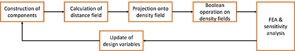
Figure 1. The proposed topology optimization approach with explicit geometric components, illustrating the process of the method.
Download figure:
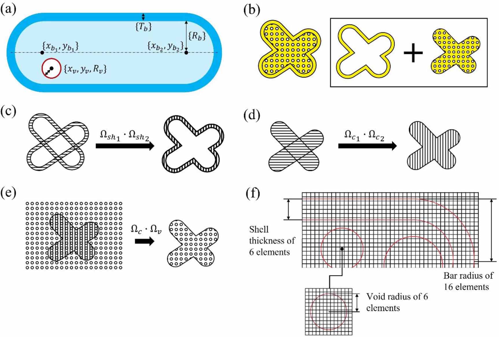
Standard image High-resolution imageTo mimic the quill's nested structure, the system of geometric components, which has the capability of moving, morphing, and overlapping, is constructed as the control unit. As shown in figure 2(a), the quill's structure is composed of three parts, including the solid shell, stiffeners whose thickness is graded from the shell to the centre, and the foamy core. When observed from a sagittal (Z–Y) view, the foamy core exhibits high density in the region adjacent to the shell and low density in the region adjacent to the centre. The foamy region's porous distribution shows some degree of stochasticity. The overall shape of the quill is illustrated in figure 2(b). As shown in figure 2(c), the shape features of the quill include a long span and a circular cross-section with gradually shrinking diameters. There is an asymmetry of the quill's shape along the horizontal direction. The different degrees of asymmetry are especially obvious at the tip of the quill. When focused on mimicking the quill's features at the micro level, the component system should provide flexible void control so that the graded foam can be implemented. The component system should divide the shell region from the core region when focusing on replicating the macro aspects of a quill. Also, the biomimetic design should guarantee that the core region is composed of a bulk of foamy material.

Figure 2. Structure information of porcupine quill: (a) sagittal (Z–Y) illustration and 3D reconstructed model of quill's hierarchical microstructure [22], (b) quill's macro structure, (c) a single long quill.
Download figure:
Standard image High-resolution imageSimplifications have been conducted to implement features of the quill's structure at both the macro and micro levels. Figure 3(a) shows the parameterized bar component and void component. The design variable set related to the  bar component at the macro level is illustrated as follows:
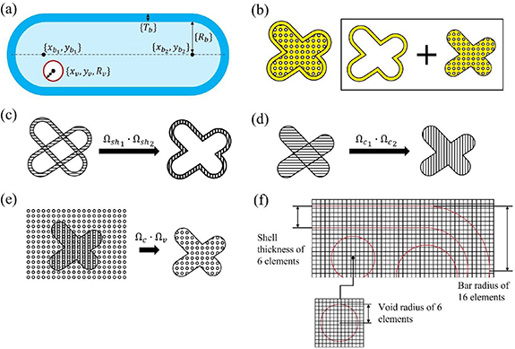
Figure 3. Construction of quill-inspired geometric components in the proposed topology optimization method: (a) parametrization of bar and void components, (b) separation of structure into solid shell and porous core, (c) operations on components to generate shell, (d) operations on components to generate core region, (e) operations on components to impose voids in core region, (f) components in the discretised grids.
Download figure:
Standard image High-resolution imagewhere the  is the design variable set of
  bar, the
  represents the coordinate of the left end point of the bar, the
  represents the position of the right end point of the bar, the
  represents the bar radius, and the
  represents the shell thickness. The design variable set related to the
  void component at the micro level is illustrated as follows:
where the  is the design variable set of
  void, the
  represents the position of the void's centre, and the
  is the radius of the void.
The bar component, which is manipulated by the movements of two endpoints  and
and  , the radius
  , and shell thickness
  , contributes to the overall structure at the macro level. The void component, which is controlled by the movement of centre
  and the radius
  , contributes to the construction of a porous core. By setting up a range of
  and
and  , good scale separations between voids and bars can be guaranteed. In addition, other design variables in equations (1) and (2) are updated within a pre-defined range during the optimization to fit the scale separation and the dimension of design space.
Including multiple components, the complete set of design variables for the quill-inspired structural optimization problem is summarized in the following:
where the  is the design variable set for all bar components, the
  is the design variable set for all void components. There is total
  bar components and
  void components.
The expression of structure is illustrated with the example shown in figure 3. The movement and size control of multiple bar components and void components can facilitate both the solid shell and foamy core features. As figure 3(b) shows, the structure is decomposed into a solid shell and a foamy core, where the voids can only be imposed inside the core. The solid shell of a bar component, which is represented in the darker blue region in figure 3(a), is obtained by the elimination of the inner part (i.e. the light blue region shown in figure 3(a)) from the bar component (i.e. the bar region enclosed by the outmost boundary shown in figure 3(a)). The overall shape is represented by the overlap of multiple bar components. The subtraction of the structure's inner section from the outmost boundary is after the overlap. As figure 3(c) shows, when multiple solid shells overlap, only the outmost region will conserve. Figures 3(d) and (e) show the operations on the core region, where the effective region is firstly constructed by the overlap of all cores of bar components. Secondly, with production operations on the density fields, voids are imposed on the effective region so that the porous core can be formed.
In the proposed method, the design space is discretised into fixed grids, which are composed of fixed four-node regular Q4 square elements. The size of components is represented and measured by the number of elements. Figure 3(f) illustrates examples including one bar component, which has a radius of 16 elements and a shell thickness of 6 elements, and one void component inside that bar component, which has a radius of six elements. As figure 3(f) shows, bar components and void components whose boundaries are represented by the red line, are imposed in the discretised design space to support the density map calculation and the finite element analysis. The successful generation of the quill-mimicking structure is based on the operations on the density fields, where the transformation of parametrized components into density fields is illustrated in figure 4. The transformation consists of three steps, including the generation of distance fields  , the generation of inverse density maps
  , and the generation of density maps
  . Firstly, the minimum distance
  between the component's boundary and each element is evaluated as the input to the projection function to obtain inverse density fields
  . Secondly, the inverse density maps for all components are assembled to obtain the density map
  . As figure 4(a) shows, the minimal distance between grids and geometric boundary is different for the middle, left, and right parts of the bar components. The distance fields
  for the
  bar component in the left circular end regions is calculated as follows:

Figure 4. From components to density field: (a) calculation of the distance between elements and boundary for bar component, (b) calculation of the distance between elements and boundary for void component, (c) the projection function to transform distance field into inverse density field.
Download figure:
Standard image High-resolution imagewhere the  is the distance between elements and the left end point
  of the
  bar, and the
  is the radius of the
  bar. When calculating the minimum distance field in the right circular end part, equation (4) is utilized where the left end point
  is replaced by the right end point
  . As figure 4(a) shows, when calculating the minimum distance field in the middle part of bar components, the calculation accounts for the offset between elements and the horizontal centreline of bar components. The distance fields
  for the
  bar component in the middle part is calculated as the following equation:
where the  is the offset between elements and the horizontal axis of the
  bar. For calculation, the offset
  can be represented by the inner product of the vector
  and the unit vector
  along the horizontal axis shown as following equations:
where the  is the vector starting from point
  to point
  .
.
As figure 4(b) shows, the minimum distance fields  for the
  void component is calculated as the following equation:
where the  is the distance between grids and the centre
  of the
  void. The
  represents the
  void's radius. As the blue dash box illustrated in figure 4(b), the movement of void components can be manipulated by setting the range of local movements
  and
and  along the horizontal and vertical direction, respectively. For small values of
  and
and  , void components are constrained to oscillate locally, leading to a more separate distribution of pores. When the value of
  and
and  increases, void components have a stronger capability of overlapping with each other, leading to a more irregular distribution of pores. This irregular distribution of pores can contribute to the generation of graded stiffeners observed from the porcupine quill's microstructure.
The projection function illustrated in figure 4(c) connects the minimum distance field and the density field. After obtaining the minimum distance field  of each component with respect to its geometric parameters, the inverse density field
  , which represents solid material as 0 and void as 1, is calculated component by component in the following equation:
where the  is the inverse density map considering only the
  component. The pre-defined factor
  is tuned to obtain the smoothness of projection. The pre-defined offset
  is tuned to blur the density at the boundary to avoid sharp features. As a result, the geometric features of components will be influenced by the offset. For instance, the actual radius of bar components and the actual radius of void components can be calculated based on the equation (9)
The density field  is obtained by the assembly of inverse density fields in the following equation:
where the feature of the structure is reserved by the production of  . The production operations on the inverse density fields contribute to the conservation of component features, whereas the representation of non-material region as 0 collapses the geometries when directly conducting production operations on the density fields without the assistance of inducing inverse density fields.
The assembly of inverse density maps is also separately applied to the shell regions of bar components, the core region of bar components, and void components. Therefore, the density fields  in the shell of bar components,
  in the core of bar components,
  representing the superposition of
  and
and  , and
, and  of void components can be represented independently. The shell is generated by eliminating inner section from overall components. As figure 3(b) shows, the density fields of the quill-inspired structure are represented as follows:
where the  represents the density fields of quill-inspired structure, which is the superposition of solid shell and foamy core. The voids are only imposed inside the core with respect to the
  term. The density map of shell is represented by
  , which is calculated as
  .
.
3. TO problem set-ups
The optimization problem setups in this study are an extension of the SIMP method, with a specific emphasis on geometric parameter-based design variables. To derive the problem setups, it is necessary to consider the connection between geometric parameters and the density map. Additionally, the sensitivity analysis adjustment must be modified based on the projection function and adjoint analysis. In all numerical examples, the proposed algorithm minimizes the structural compliance, which is demonstrated below:
where the  is the density at element
  of quill-inspired structure obtained from equation (10) the
  represents the minimal density at non-material elements, the
  is the penalty parameter to punish grey region, the
  represents the displacement vector at element
  , and the
  represents element stiffness matrix for purely solid element. The setup of the minimum compliance problem is shown:
where the  is the design variable set to manipulate bar and void components obtained from equation (3). Global stiffness matrix
  , displacement vector
  , and the force vector
  assists the construction of constitution function. Volume of design space
  and the upper bound of the volume fraction
  helps the generation of volume constrints.
The sensitivity analysis is obtained from the adjoint analysis, chain rule, and the density calculation in equation (11). The procedure of sensitivity analysis is shown in the following:
where the  represents each design variable inside
  in equation (3), the
  is the density for the core (i.e. inner section of bar) at element
  , the
, the  is the density for the bar, the
  is the density for the void, the
  ,
,  , and
, and  are the distance fields for the corresponded density maps. The
  part, which is similar as the sensitivity term in SIMP algorithm, is derived by conducting the adjoint analysis:
The  ,
,  , and
, and  terms are derived based on the projection function in equation (8). The
  ,
,  , and
, and  terms are derived with respect to equations (4)–(7).
4. Case studies
4.1. Case study 1: long-span beam
For all numerical examples, the target is to resolve the minimum compliance problem as shown in equation (13) The elastic isotropic model is adopted for solid material, where the Young's modulus  and Poisson's ratio
  are assumed to be 1 and 0.3, respectively. The minimal density
  is set to be
  . The penalty
  and the projection factor
  are both set to be 2. The offset
  in projection function is set to be 3.
Porcupine's quill can provide protection functionality with its outstanding bending resistance. The specific aspect ratio as well as the quill's exterior boundary shape provides excellent guidance for the long-span beam design. As figure 5(a) shows, to further transform the quill's loading conditions into a suitable form to fit the TO problem, the setup of the three-point bending test (i.e. figure 5(b)), which has been widely applied to investigate the structural bending performance, is adapted into the proposed validation scheme. As a result, the loading scheme illustrated in figure 5(a) is set to simulate the bending that the quill may undergo in the natural environment.
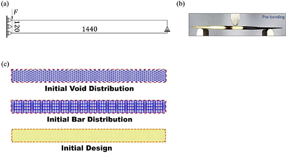
Figure 5. Long-span beam problem: (a) design space, (b) experimental settings for 3-point bending tests of quills, (c) initial design of long-span beam problem.
Download figure:
Standard image High-resolution imageFigure 5(a) shows the discretisation of design space for the long-span beam problem. The design space is composed of a mesh that has the dimension of  regular Q4 elements, which is in accordance with the aspect ratio from the literature [38]. The symmetric boundary conditions are set along the leftmost edge and negative point load are applied to the top left conner. The translational movement along the vertical direction is fixed at the middle point of the rightmost edge as support, which is set to mimic the bending of quill under the natural conditions. The setup of loadings and boundary conditions are also in accordance with the modified version of the experimental setups of 3-point bending tests, which is shown in figure 5(b). Under most circumstances, quills are contacted with objects at their tips, leading to a large bending moment at their tips.
Figure 6 illustrates the optimization results of the long-span beam with void size control. As figure 3(f) shows, the void radius in the long-span beam void size control analysis is represented by elements. The optimized structure from the TO has low compliance under the bending loadings, which is assumed to have good bending resistance. As the upper bound of the void radius changes from 8 to 12 elements, where the lower bound of the void radius remains unchanged, the long-span beam with small voids (shown in figure 6(a)) gradually changes to the long-span beam with large voids (shown in figure 6(c)).
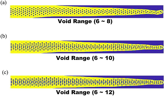
Figure 6. Optimization results of the long-span beam with void size control: (a) optimized long-span beam with void radius from 6 to 8 elements, (b) optimized long-span beam with void radius from 6 to 10 elements, (c) optimized long-span beam with void radius from 6 to 12 elements.
Download figure:
Standard image High-resolution imageThe asymmetry of the beam along the horizontal axis, which is observed in all three cases, is caused by the adaptation of the beam's shape to resist the bending moment induced by the loadings. Due to the smaller size of voids imposed in the case shown in figure 6(a), more material needs to be eliminated at the macro level, leading to more narrowing of the beam's cross-section. The more narrowing of the beam's cross-section causes more obvious asymmetry of the beam along the horizontal axis. The asymmetry around the tip adjacent to the rightmost boundary of the design is the extension of the beam asymmetry along the horizontal axis. As a result, the upwarp of the tip observed in figure 6(a) can be observed. When the void radius increases, the tip becomes more symmetric due to the less asymmetry of the beam along the horizontal axis, leading to much less upwarp of the tip observed in figure 6(c).
According to the void size distribution, the region adjacent to the shell has voids in smaller radii, leading to high-density foams. For the region adjacent to the horizontal centreline, big voids cluster for all three cases, leading to low-density foams. The characteristics of void size distribution according to the design from TO illustrate the similar features observed in the natural quill's structure (shown in figure 2(a)), leading to a functionally graded beam design.
Figure 7(a) shows the void radius information of the long-span beam with void size control. As the upper bound of the void radius design variable  changes from 8 to 12 elements, where the lower bound of the void radius design variable remains unchanged, the minimum actual void radius of the design
  in figure 6(a) gradually decreases from
  to
to  elements for the design in figure 6(c). The maximum actual void radius of the design
  in figure 6(a) increases from
  to
to  elements for the large void design in figure 6(c). All three cases illustrate a similar average actual size of voids. In addition, the size of voids has little impact on the average size of the actual bar radius and shell thickness according to the information from figure 7(b).
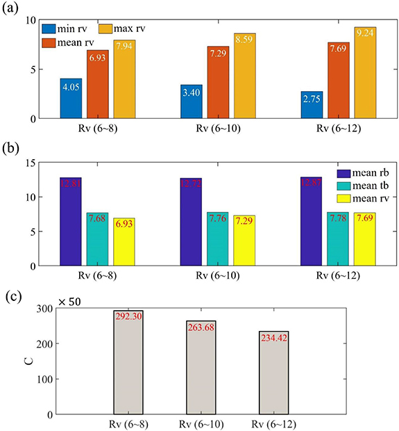
Figure 7. Parameter information of optimized long-span beam: (a) void components information of long-span beams with void radius control, (b) bar components information of long-span beams with void size control, (c) compliance of long-span beams with void size control.
Download figure:
Standard image High-resolution imageThe impacts of void radius on compliance are shown in figure 7(c), where the relaxation of the void size's upper bound can decrease compliance. As summarized in table 1, the increase of pore size's upper bound from 8 to 12 elements can decrease compliance by approximately 20%, leading to a much stiffer long-span beam.
Table 1. Compliance of long-span beam with pore size control.
| Aspect ratio |

|

|

|

|

| Compliance | Compliance after increasing  (%) (%) | |
|---|---|---|---|---|---|---|---|---|
| Long-span beam | 12 | 2–15 | 6–8 | 2–8 | 8 | 8 | 14 615 | / |
| Long-span beam | 12 | 2–15 | 6–10 | 2–8 | 8 | 8 | 13 184 | 90.2% |
| Long-span beam | 12 | 2–15 | 6–12 | 2–8 | 8 | 8 | 11 721 | 80.2% |
4.2. Case study 2: short-span beam
The effectiveness of designing a quill-inspired long-span beam has been illustrated in section 4.1. To explore the influence of aspect ratio, short-span beam problems are set up as illustrated in figure 8. The analysis of von Mises stress distribution, which is an important index of structural failure, is conducted on the topology-optimized short-span beam for further investigation of the fail-safe mechanism. As figure 8(a) shows, the loadings and boundary conditions are the same as the setups in the long-span case. The discretisation of design space is composed of a mesh that has a dimension of  regular Q4 elements. In addition, the initial designs of voids and bars of the short-span beam case are composed of a concentrated arrangement of bar components.
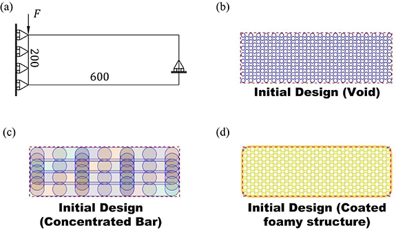
Figure 8. Short-span beam problem: (a) design space, (b) initial distribution of voids for short-span beam, (c) initial design of bars for short-span beam, (d) initial design of short-span beam.
Download figure:
Standard image High-resolution imageFigure 9 shows short-span beam designs with shell thickness control. As figure 3(f) shows, the shell thickness in the short-beam shell control analysis is represented by elements. As the upper bound of shell thickness changes from 10 to 14 elements, whereas the lower bound of the shell thickness changes from 2 to 6 elements, the compliance only decreases slightly. The change from the large shell thickness to the small shell thickness can be clearly observed in figures 9(a) and (c).
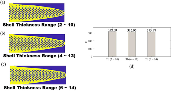
Figure 9. Short-span beam design with shell thickness control: (a) short-span beam with shell thickness from 2 to 10 elements, (b) short-span beam with shell thickness from 4 to 12 elements, (c) short-span beam with shell thickness from 6 to 14 elements, (d) compliance of short-span beams with shell thickness control.
Download figure:
Standard image High-resolution imageAs illustrated in figure 9(d), increasing the lower bound and upper bound of shell thickness can slightly decrease the compliance of the optimised short-span beam. However, the modification of shell thickness has very limited impacts on compliance. As summarised in table 2, the maximum difference of compliance between short-span beams with thickness control is only approximately 2%.
Table 2. Compliance of short-span beam with shell thickness control.
| Aspect ratio |

|

|

|

|

| Compliance | Compliance after increasing  (%) (%) | |
|---|---|---|---|---|---|---|---|---|
| Short-span beam | 3 | 24–32 | 6–12 | 2–10 | 8 | 8 | 319 | / |
| Short-span beam | 3 | 24–32 | 6–12 | 4–12 | 8 | 8 | 316 | 99.1% |
| Short-span beam | 3 | 24–32 | 6–12 | 6–14 | 8 | 8 | 313 | 98.1% |
To further investigate the structural functionalities brought by the quill's features, the normalized von Mises stress distributions of the short-span beam and the corresponding hollow shell under the same loadings are compared. To obtain the von Mises stress distribution, the isotropic elastic material model is adopted, where the Young's modulus  and Poisson's ratio
  for solid elements are 1 MPa and 0.3, respectively. Some outliers exist in the original von Mises stress map. These outliers cause most of the effective data located inside the narrow range, leading to a blurry stress map. To illustrate the clearer variation of stress, the initial von Mises stress map is modified where the value larger than 0.18 MPa is cut off. The cut-off operation eliminates 88 extreme data points from the dataset that has a size of 120 000, which is the total number of elements. After the cut-off operation, the normalized von Mises stress map is calculated as:

where the  represents von Mises stress at element
  , and the
  is the upper bound of stress normalization at element
  . After normalization, the normalized dimensionless von Mises stress
  is equal to 1.0 when the
  is evaluated as 0.18 MPa.
The modified von Mises stress map of the quill-inspired short-span beam is shown in the bottom part of figure 10(a). The stress is mainly concentrated in the shell, where the stress in the core decreases from the skin to the centre of the structure. The concentration of stress in the shell region illustrates that the shell withstands most of the loadings. The calculation of von Mises stress is then conducted to the hollow shell, which is extracted from the quill-inspired short-span beam (i.e. the design shown in the bottom part of figure 10(a)) by eliminating the foamy core with conservation of solid shell. As figure 10(b) shows, the normalized von Mises stress map of the shell with a hollow inner section, which is extracted from the short-span beam, illustrates that the shell is under super high stress without the existence of the foamy core. Compared to the normalized dimensionless von Mises stress value of a hollow shell, which is equal to 1.0, the normalized stress value of a shell with a foamy core is around 0.3–0.7. As a result, the existence of a foamy core can relax the stress in the shell region to approximately 40%.

Figure 10. Normalized von Mises stress distribution of short-span beam under linear static analysis (shell thickness 2 ∼ 10 elements case): (a) distribution of the topology optimized structure, (b) distribution of corresponded hollow shell.
Download figure:
Standard image High-resolution imageThe relaxation of high stress in the shell region illustrates the benefits of learning from the quill's structure. The decrease of stress in the shell region contributes to the less yielding of material, leading to less possibility of structural failure. For the short-span beam case, the less yielding of the material also leads to better bending-resisting performance. Similar benefits including failure mitigation have also been analysed with experiments in the literature [20].
4.3. Case study 3: MBB beam
The MBB problem is set to prove the correctness of the proposed algorithm. Figure 11(a) shows the discretisation of design space, which is composed of a mesh that has a dimension of  regular Q4 elements. The negative point load is applied to the left top corner. The symmetric boundary condition along the vertical direction is set to the left side of the design space for simplification. The translational movement along the vertical direction is fixed at the right bottom corner as support.
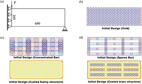
Figure 11. MBB problem: (a) design space, (b) initial distribution of voids for MBB, (c) initial design with concentrated distribution bar, (d) initial design with sparse distribution bar.
Download figure:
Standard image High-resolution imageFigure 11(b) shows the initial distribution of void components for the MBB problem. The initial design of void components is same for both the concentrated case (i.e. figure 11(c)) and the sparse case (i.e. figure 11(d)). There are 15 rows of void components, and each even row has 19 voids. For each odd row, there are 20 void components. As figure 11(c) shows, the concentrated distribution of bar components is set for the quill-inspired MBB design, where the core region is composed of a bulk of foamy material. As figure 11(d) shows, the sparse distribution of bar components is set for the truss-based MBB design, which is utilized to validate the correctness with comparison to the SIMP algorithm. As the initial design illustrated at the bottom of figure 11(d), only the void components inside the core region account for the structural performance, whereas the void components enclosed by the blue boundary outside the core region are inactive.
The upper bound of the volume fraction in the MBB beam design is set to be 0.5. To examine the correctness of the proposed algorithm, volume constraint, design space, and the objective function are set to be the same when generating results from the open-source top88 SIMP code [39]. The penalty  in SIMP is set to be 3. The sensitivity filtering mechanism is selected and the filter radius
  is set to 8, which is the same as the lower bound of the bar radius in the thin truss-based case.
Figures 12(a)–(d) show the optimized MBB beam by the proposed algorithm and the SIMP algorithm from the top88 open-source code [39]. The range of bar components' radius, which is regarded as design variables described in equation (1), is highly related to the overall shape of the optimized design. As figure 3(f) shows, the bar radius in the MBB bar size control analysis is represented by elements. As the lower bound of the bar radius changes from 8 to 24 elements, where the upper bound of the bar radius changes from 16 to 32 elements, the thin truss-based porous MBB (shown in figure 12(a)) gradually changes to thick truss-based porous MBB (shown in figure 12(b)). Finally, the MBB with a bulk of porous core is facilitated as shown in figure 12(c). The reason for the generation of the MBB with a bulk of porous core is because such MBB has a boundary in an organic shape. Investigating the performance of MBB with boundaries in organic shape and porous infillings is vital because these features are the most significant ones from the observation of the quill's biological structures.

Figure 12. Optimization results of the MBB problem with bar radius control: (a) optimized MBB with bar radius from 8 to 16 elements, (b) optimized MBB with bar radius from 16 to 24 elements, (c) optimized MBB with bar radius from 24 to 32 elements, (d) optimized MBB by SIMP [39], (e) the contour of von Mises stress of optimized MBB with bar radius from 8 to 16 elements under linear static analysis, (f) the contour of von Mises stress of optimized MBB with bar radius from 24 to 32 elements under linear static analysis.
Download figure:
Standard image High-resolution imageCompared with the optimized MBB from the SIMP algorithm (shown in figure 12(d)), the thin truss-based porous MBB (shown in figure 12(a)) has a similar truss distribution, which is composed of two X-shape joints in the middle region, one inclined beam as inner support in the leftmost region, and one inclined beam as inner support in the rightmost region. The optimized thin truss-based MBB from the proposed method illustrates a similar overall shape as the result from SIMP. From the topologies during the optimization illustrated in figure 13, the algorithm tends to manipulate bar components at the first 30 iterations. After the rough boundary of structure at the macro level has been determined by the bar components, the algorithm tends to manipulate the circular components to obtain optimized distribution of pores.

Figure 13. Topologies during optimization: (a) MBB with bar radius from 8 to 16 elements, (b) MBB with bar radius from 24 to 32 elements.
Download figure:
Standard image High-resolution imageTo investigate the benefit of adopting the organic shape observed in the porcupine quill's structure, the von Mises stress contours of both thin truss-based MBB (shown in figure 12(f)) and MBB with organic exterior boundary (figure 12(e)) are generated. Because the as-manufactured samples are fabricated with Polylactic Acid (PLA) material, the PLA material properties are adopted for the evaluation of von Mises stress distribution. Due to the usage of the same PLA filament and fabrication conditions, the properties are determined from the literature [40], where Young's modulus  and yield strength
  is set to 2100 MPa and 47 MPa, respectively. As illustrated in figures 12(e) and (f), 250 N load and 500 N load are applied to replace the virtual load (i.e.
  in figure 11(a)). Compared to the thin truss-based MBB (shown in figure 12(f)), the MBB with an organic exterior boundary (figure 12(e)) has a more uniform distribution of stress in the shell region. The stress transition in the thin truss-based MBB (shown in figure 12(f)) is less efficient with a stress concentration at the region where loads are applied, whereas the whole solid shell in MBB with organic exterior boundary (figure 12(e)) is effective for bearing the applied load.
Figure 14 shows the optimization history and the compliance data of the optimized design. As figures 14(a) and (b) show, the proposed algorithm has good convergence. As figure 14(c) shows, the optimized MBB from the proposed algorithm has comparable compliance to the result from SIMP. There is a tendency for compliance to converge to the result from SIMP by reducing the size of the bar radius, showing that the proposed approach is valid and effective. The compliance increases when the radius of bar components increases. As summarized in table 3, the compliance of thick truss-based MBB is 12.3% higher than the compliance of thin truss-based MBB. If further increase the radius of bar components, the compliance of MBB with organic shape is 48.9% higher than the compliance of thin truss-based MBB.
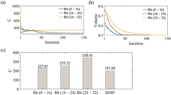
Figure 14. Optimization history of the MBB problem with bar radius control: (a) compliance (C) history, (b) volume fraction history, (c) bar graph of compliance for the optimized MBB.
Download figure:
Standard image High-resolution imageTable 3. Compliance of MBB beam with different exterior boundary.
| Aspect ratio |

|

|

|

|

| Compliance 
|
 after increasing after increasing  (%) (%) | |
|---|---|---|---|---|---|---|---|---|
| Thin truss | 3 | 8–16 | 6–12 | 4–12 | 8 | 8 | 227 | / |
| Thick truss | 3 | 16–24 | 6–12 | 4–12 | 8 | 8 | 255 | 112.3% |
| Organic shape | 3 | 24–32 | 6–12 | 4–12 | 8 | 8 | 338 | 148.9% |
The investigation illustrates that there is a trade-off between the stiffness and stress concentration of as-designed structures, where the structure with high stiffness tends to have more severe stress concentrations. Due to the stochastically distributed pores that commonly exist in the infillings of the quill's structure, the investigation of the benefit of stochasticity in pore distribution is quite important for revealing the excellence brought by the quill's features. Therefore, the stress distributions of the MBB in organic shape are further investigated by gradually increasing the stochasticity in the distribution of pores.
To facilitate the stochasticity in the distribution of pores, the range of local movement for void components is increased to enhance the merging of void components. As illustrated in figure 4(b), the local movement of void components is constrained inside a rectangular box. When the rectangular box is set to be small (e.g.  case illustrated in figure 12(c)), pores are constrained to oscillate at their initial positions, causing the regular distribution of pores in the infilling of the structure. When the size of the rectangular box increases, the range of pores' oscillations increases as well, leading to the possibility of large amounts of merging and overlapping between pores. These indeterminate but possible overlapping between void components can provide stochasticity in the distribution of pores.
Figure 15 illustrates both the design and von Mises stress contour of MBB with randomly distributed pores via control of the local movement of void components. As figures 15(a) and (b) illustrate, the distribution of pores becomes more stochastic with the increase of  and
and  from 8 elements to 40 elements. One benefit of the stochastic distribution of pores is the mitigation of von Mises stress in the shell region. As illustrated in figure 15(a) and summarized in table 4, the stress level in the shell is decreased to 88.6% of the stress level in the
  case by increasing
  and
and  from 8 elements to 24 elements. When further increasing the
  and
and  to 40 elements, the stress level in the shell is decreased to 78.2% of the stress level in the
  case. Another benefit of relaxing the local movement of void components is the stronger mimicking capability of porcupine quills' features. As the black lines in the design part of figure 15(b) illustrates, the stochastic distribution of pores can assist the construction of stiffeners that have graded thickness from the shell to the centre of the beam.
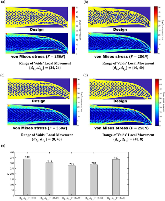
Figure 15. Parametric study on range of voids' local movement: (a) the contour of von Mises stress of optimized MBB with range of voids' local movement  elements, (b) the contour of von Mises stress of optimized MBB with range of voids' local movement
  elements, (c) the contour of von Mises stress of optimized MBB with range of voids' local movement
  elements, (d) the contour of von Mises stress of optimized MBB with range of voids' local movement.
Download figure:
Standard image High-resolution imageTable 4. Average von Mises stress of MBB beam in organic shape with  control.
 (mm) (mm) |
 (mm) (mm) | Average von Mises stress  (MPa) (MPa) |
 after increasing after increasing  , ,  (%) (%) | Average von Mises stress at shell region  (MPa) (MPa) |
 after increasing after increasing  , ,  (%) (%) | |
|---|---|---|---|---|---|---|
| MBB | 8 | 8 | 12.99 | / | 21.89 | / |
| MBB | 24 | 24 | 12.51 | 96.3% | 19.40 | 88.6% |
| MBB | 40 | 40 | 12.17 | 93.7% | 17.13 | 78.2% |
| MBB | 8 | 40 | 12.23 | 94.1% | 17.67 | 80.7% |
| MBB | 40 | 8 | 12.93 | 99.5% | 21.44 | 97.9% |
From the observation of quills' features illustrated in figure 2(a), the stiffeners and foam are graded from the shell to the centre of the quill along the cross-section direction. Along the sagittal direction, there are a few grading of features. To investigate the mechanism, the  and the
  cases are generated to represent the graded design among the cross-section and the graded design along the sagittal direction, respectively. As illustrated in figure 15(c) and summarized in table 4, the grading of features among the cross-section contributes to the decrease of stress level at the shell region (80.7% of the stress in
  case). For the grading of features mainly along the sagittal direction, the stress level is 97.9% of the stress in
  case.
case.
When comparing the compliance of MBB with different degrees of stochasticity in the distribution of pores, as illustrated in figure 15(e), the increase in the stochasticity can contribute to the lower compliance of MBB. When comparing the compliance of MBB with different grading directions, as illustrated in figure 15(e), the grading along the cross-section direction has the main impact on the decrease of compliance. With the comparison of stress distribution and compliance between  and
and  cases, the reason for only grading features among the cross-section in the quill's structure is elaborated.
Although the analysis based on the stress contour and compliance can illustrate the structural excellence of applying organic shape and stochastic distribution of pores, this structural excellence needs to be further explored and elaborated with quantitative evidence. Therefore, the behaviour of the quill-inspired beam is examined by conducting the three-point bending test. The manufacturability of optimized MBB is validated by the MEX fabrication. All samples are fabricated with an open-source Prusa i3 MK3 3D printer, where the 1.75 mm PLA filament is extruded from a 0.4 mm extrusion nozzle during the fabrication. Three-point bending tests are conducted on the three different MBB samples, which are shown in figure 16, to further validate the failure mitigation capabilities of the quill-inspired structure. The evaluation criterion including energy absorption (EA), specific energy absorption (SEA), and specific bending load ( ) is calculated as follows [41]:


Figure 16. As-designed MBB beams from optimization results (left) and corresponding as-built samples (right): (a) optimized MBB with bar radius from 8 to 16 elements, (b) optimized MBB with bar radius from 16 to 24 elements, (c) optimized MBB with bar radius from 24 to 32 elements.
Download figure:
Standard image High-resolution imagewhere  represents the bending load at deflection
  , and
, and  represents the total mass of the structure. The upper bound
  is set to the deflection at peak load for the calculation of EA and SEA [41]. The specific bending stiffness of the beam is calculated as the slope of the specific bending load-deflection curve at the initial elastic region.
Before fabrication, the MBB designs shown in figures 12(a)–(c) are scaled, thickened, and mirrored to generate the 3D ideal model in the STL format, which is shown in the left part of figure 16. Each sample has a length of 180 mm and a width of 30 mm. The STL model, which is obtained by thickening the 2D profile to 12 mm, is sliced with 0.2 mm layer height to generate the G-code using the PrusaSlicer software. All samples are tested to failure utilizing an Instron 5596 machine, where a 2 mm min−1 testing speed and a 5 kN load cell are adopted. The force-deflection curves are illustrated in figure 17(a). For each type of MBB beam, the 75% peak load, peak load, and 15% drop after peak load points are highlighted in the force-deflection curve. The image sequences corresponding to the initial, 75% peak load, and peak load points are shown in figures 17(a)–(c).
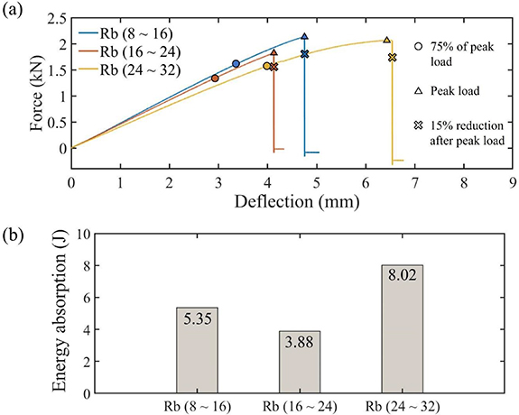
Figure 17. Results of three-point bending tests: (a) force-deflection curve, (b) energy absorption.
Download figure:
Standard image High-resolution imageAs figure 17(a) shows, both the MBB with thin trusses (i.e. the blue curve), which has a range of bar radius from 8 elements to 16 elements, and the MBB with thick trusses (i.e. the red curve), which has a range of bar radius from 16 elements to 24 elements, have an abrupt fracture after the peak load. The deflection of the MBB with thin trusses before the 75% peak load is 3.33 mm, which takes 70% of the total deflection. For the MBB with thick trusses case, the deflection before the 75% peak load is 2.97 mm, which takes 72% of the total deflection. For the MBB with a bulk of foamy core, the deflection before the 75% peak load is 3.92 mm, which takes 60% of the total deflection. The strength of the MBB with a bulk of foamy core, which has a peak load of 2.06 kN, is very close to the strength of the MBB with thin trusses, which has a peak load of 2.13 kN.
In conclusion, the MBB with a bulk of foamy core has a more than 10% increase of the deflection after 75% peak load when compared to the truss-based MBB. The peak load of MBB with a bulk of foamy core is 96.7% of the peak load for the thin truss-based MBB. Based on the increased deflection without reduction of peak load, MBB in organic shape illustrates higher load-bearing capability, leading to the remarkable bending-resistance performance. The existence of quill-inspired features (i.e. the combination of a solid shell and a bulk of foamy core) contributes to the increase of structural ductility without sacrificing much strength under bending loads. From the literature [19], the shell of the quill contributes to the main capability of load bearing. Considering the efficient stress transition in the shell region of MBB with an organic shape, the shell tends to bear the load uniformly. Compared to the MBB with an organic shape, the thin truss-based MBB, which has a stress concentration at the region where the load has been applied, tends to have local failure at the specific region.
The comparison of the energy absorption of all three designs is illustrated in figure 17(b). The energy absorption of the MBB with a bulk of foamy core, which has a range of bar radius from 24 elements to 32 elements, is 49.9% higher than the energy absorption of the MBB with thin trusses, which has a range of bar radius from 8 elements to 16 elements. The existence of quill-inspired features (i.e. the combination of a solid shell and a bulk of foamy core) provides an outstanding improvement in energy absorption capability. As summarized in table 5, both the SEA and specific bending stiffness of the quill-inspired beam are comparable with the dome-based beam structure [41].
Table 5. SEA and specific bending stiffness of porcupine quill-inspired MBB.
 (mm) (mm) |
 (mm) (mm) |
 (mm) (mm) |
 (mm) (mm) |
 (mm) (mm) | SEA (J g−1) | Specific bending stiffness ((N g−1) mm−1) | |
|---|---|---|---|---|---|---|---|
| MBB | 8–16 | 6–12 | 4–12 | 8 | 8 | 0.122 | 10.59 |
| MBB | 16–24 | 6–12 | 4–12 | 8 | 8 | 0.088 | 10.11 |
| MBB | 24–32 | 6–12 | 4–12 | 8 | 8 | 0.182 | 9.26 |
| Variable-large [41] | / | 0.178 | 17.54 | ||||
| Variable-small [41] | / | 0.084 | 14.92 | ||||
| Uniform-large [41] | / | 0.11 | 9.68 | ||||
| Uniform-small [41] | / | 0.063 | 8.43 | ||||
| Solid dome [41] | / | 0.123 | 13.12 | ||||
The failure mode of the structure can be observed in figure 18(d). For the truss-based MBB beams (i.e. the cases shown in figures 18(a) and (b)), the failure of the structure is mainly due to the fracture in the middle of the beam, where a large amount of bending moment generates stress concentration at the top region where the load has been applied. The stress concentration at the region where the load has been applied is illustrated in figure 12(f). For the MBB with a bulk of foamy core (i.e. the case shown in figure 18(c)), the failure of the structure is mainly due to the near 45° shear band, which is a typical failure mode in engineering materials. Dislike truss-based MBB beams whose failure is at the truss level, the failure of the MBB with a bulk of foamy core is similar to the material failure (i.e. the near 45° shear band). This is related to the uniform stress distribution in the shell region as illustrated in figure 12(e). As a result, the existence of quill-inspired features (i.e. the combination of a solid shell and a bulk of foamy core) can increase structural stability according to the failure mode.

Figure 18. Deformation of optimized MBB under three-point bending: (a) optimized MBB with bar radius from 8 to 16 elements, (b) optimized MBB with bar radius from 16 to 24 elements, (c) optimized MBB with bar radius from 24 to 32 elements, (d) optimized MBB after failure.
Download figure:
Standard image High-resolution image
5. Conclusion
In the proposed method, we constituted an explicit component-based TO algorithm with the combination of porcupine quill's foamy features, leading to the beam design with bending resistance as well as fail-safe functionality. With three different case studies, the proposed method was validated to have the capability of designing various bending-resistant porous beams. With the analysis of von Mises stress contour, the quill-inspired design was illustrated to show the stress relaxation in the shell region due to the existence of a foamy core. In addition, three-point bending tests were conducted on the optimized MBB beams manufactured by the MEX technique to explore the structural performance under large deformation. The following conclusions are made:
- The proposed approach enables the conservation of quill-inspired features by explicitly describing geometric components. Quill-inspired designs with organic boundaries and stochastic distribution of pores were implemented.
- Long-span beam, short-span beam, and MBB beam designs were illustrated to show the various potential applications of the proposed approach. The parametric study illustrates that the larger void size can contribute to a stiffer beam, whereas the shell thickness contributes to a limited increase in stiffness.
- From the numerical study, the presence of a stochastic distribution of pores in the foamy core can alleviate high stress in the shell region, leading to a stronger resistance to failures. The organic boundary in quill-inspired structure tends to have a more efficient stress transition under load, leading to a potential of more uniform deformation under bending. The quill-inspired TO approach has been shown to be an effective tool for designing stress-relaxed porous structures based on the natural structure of quills.
- From the result of three-point bending tests, the existence of quill-inspired features (i.e. the combination of a solid shell and a bulk of foamy core) contributes to the increase of structural ductility without sacrificing much strength under bending loads. The existence of quill-inspired features can increase structural stability by changing the failure mode.
- Compared to the truss-based MBB beam, the existence of quill-inspired features (i.e. the combination of a solid shell and a bulk of foamy core) provides a 49.9% improvement in energy absorption capability.
The proposed method can create foamy infillings inspired by quills while maintaining a solid shell. The effectiveness of the quill's structure has been validated through TO. Additionally, the advantages of the quill's structure have been incorporated into the proposed method, resulting in a novel approach to bio-mimic design. These research findings can be further investigated and applied to a wide range of bio-mimic design applications.
Acknowledgments
The authors acknowledge the facilities, the scientific and technical assistance of the RMIT Centre of Additive Manufacturing (RCAM) and the RMIT Microscopy and Microanalysis Facilities (RMMF). This is work is also dedicated to the Vale Distinguished Professor Adrian Mouritz for his support and guidance.
Data availability statement
The data cannot be made publicly available upon publication because they contain commercially sensitive information. The data that support the findings of this study are available upon reasonable request from the authors.