

Abstract
The shell of the chambered nautilus is one of the few examples in nature of a biologically derived one-atmosphere pressure housing, which the animal uses to maintain neutral buoyancy via a series of sealed chambers. Extant species such as Nautilus pompilius live at depths from 200 to 800 m, and similar depth ranges have been hypothesized for their hyper diverse but extinct relatives, the ammonoids. Given the evolutionary success of these molluscan clades, their complex shell morphologies may reveal pressure-tolerant geometries comparable to the 'ideal' ones currently used in deep-sea marine robotics: simple spheres and cylinders, which have minimized surface area to volume ratio and easier manufacturability. We modeled and empirically tested 3D-printed bioinspired pressure housings for deep-sea applications using high resolution stereolithography 3D printing. These designs were modeled on the shells of N. pompilius and were compared to conventional 3D-printed spheres with similar wall thicknesses and implodable volumes. Two nautilus-inspired models with internal supports designed after their septal walls (one concave, one convex) had a higher-pressure tolerance compared to hollow models, but none outperformed spherical models with the same outer-wall thickness. Although spheres outperform the nautilus-inspired housings, the methods developed here show that pressure housings with complex geometries can be printed by additive manufacturing and empirically tested. From a biological perspective, this method can be a new tool for empirically testing viable depth tolerances for extinct coiled cephalopod morphologies.
Export citation and abstract BibTeX RIS
1. Introduction
Shelled cephalopods, including extant nauitlids, are the most famous examples of extant animals that produce biological pressure vessels, capable of maintaining about one atmosphere of pressure internally while experiencing high external hydrostatic pressures [1, 2]. Similarly, human-manufactured pressure vessels are used to house electronics at depth for robotics and manned submersible applications, while also playing a role in buoyancy control. Historically, these pressure vessels are hollow spheres or cylinders because of their low surface area to volume ratios, which reduces stress under hydrostatic pressure, and a range of materials and design considerations exist [3]. From a pressure vessel design perspective, an idealized nautilus shell would be as spherical as possible, to decrease the surface area to volume ratio, however Nautilus pompilius is instead laterally compressed, which streamlines the shell in the direction of movement. Inside its shell, N. pompilius has septal walls segmenting each chamber, a feature which is rarely utilized in manufactured pressure vessels. Internal walls are uncommon in pressure vessels, partially due to the practicality of accessing the electronics with internal buttressing, but also because of the complexity of manufacturing. 3D printing has opened possibilities for creating pressure vessels with unique forms and complex geometries that could not have been reasonably attempted through traditional manufacturing methods.
Millions of years of evolution have shaped the complex geometry of nautiloid shells, offering a 'natural' experiment in the relationship between form and performance at various water depths. Sealed chambers inside nautiloid shells are filled with gas allowing for the animal to remain buoyant at depth, while precise buoyancy is regulated by moving fluid into and out of the chambers through the siphuncle [1, 4, 5]. The gas-filled chambers remain at about one atmosphere, which results in the shell's outer walls experiencing hydrostatic pressure as a function of depth due to the pressure differential inside and outside of the shell [1, 2]. Thus, stress on the cephalopod shell increases with bathymetric depth [6]. Implosion experiments have been performed on live specimens of cephalopods, including N. pompilius, providing an estimated implosion depth at 785 m [7–10]. More conservative estimates define the maximum range at about 700 m [11]. Estimates for other extant cephalopod shell morphologies range from 100 to 1000 m. while extinct species estimates are over a similar range or deeper from analysis of fossilized specimens [12, 13]. Inferring depth tolerances for extinct coiled cephalopods have been hypothesized as similar to those of extant members [12, 13], but estimates from fossils remain problematic; morphologies may have a many-to-one mapping of form to function [4, 14] that complicate interpretations of shell strength indices [12].
Finite element analysis (FEA) has become an increasingly popular modeling technique to evaluate the performance of shells under pressure, but rather than define an absolute depth range, it is more often used to make relative comparisons of pressure tolerance among different morphologies [12, 15, 16]. Ammonoid fossils show increasing septal complexity or septal folds through evolutionary history and the function of complexity folded septa is contested [14, 17, 18]. For example, FEA has indicated that increased septal complexity results in increased principal stress on the septa but increased the tolerance to point loads, which mimic biting forces from known predators [15, 19]. Thus, predation rather than tolerance to hydrostatic pressure may have shaped the evolution of increased septal complexity [20], which complicates interpretations of the relationship between shell form and bathymetry in either relative or absolute terms. Using similar FEA methodologies and in contradiction to previous findings, more septal folds have also been found to decrease the principal stress on individual septa [16]. Both findings focus on the modeled performance of individual septa, which limits their application to true septal or whole shell performance. Further, both cases modeled septal performance with an outer wall set to a perfect cylinder, which may miss a critical interaction between the shapes and counts of individual septa and the entire shell (often narrow, non-cylindrical and non-spherical). Septal complexity's effect on pressure tolerance is a highly contentious topic, with studies claiming that it increases, decreases, and, in the case of Lemanis et al (2020), that it is not correlated to depth tolerance [15, 16, 21]. In a response to a comment on Lemanis 2020, after questioning his own findings, Lemanis calls for the field to move on to new ideas and experiments due to the inconclusive nature of the current findings [22].
Applications of FEA to full, 3D shell morphologies acquired from CT scanning can improve the resolution of performance modeling. Analyses of hydrostatic loading and point loads on full shells of N. pompilius, Cadoceras sp., and Spirula spirula revealed finer patterns of hydrostatic loading, i.e. its concentration on the final septum, and that resistance to point loading is directed along a suture [12, 23]. These results also included a simplistic model of the shell's material properties via its nacre, which forms a brick-like structure of aragonite tablets [4]. This holistic approach improves the relative comparisons of shell morphologies [15, 16], but this material remains difficult to model and thus limits the prediction of actual, N. pompilius shell performance [12]. Thus, hand calculations are often advised to cross-check the performance of pressure vessels determined using FEA [24]. However, hand calculations become impractical with increasing complexity of the pressure vessel's geometry, and practical testing of physical models becomes a viable alternative to corroborate FEA results with the application of 3D printing.
Fused deposition modeling (FDM) can print morphologically accurate 3D shells for certain practical tests of performance, such as the righting moment of cephalopod shells and their fluid retention as a function of septal complexity [18, 25–27]. One conclusion drawn from this kind of experimentation was that the fluid retention from complex, folded septa in ammonoids would have allowed better control over buoyancy compared to extant nautilids. However, FDM printers produce low-resolution prints with ridged surfaces and permeable layers that are not watertight under significant pressure, particularly for o-ring sealing surfaces, which precludes the practical testing of these morphologies as pressure vessels.
Stereolithography (SLA), selective laser sintering, and electron beam melting 3D printing techniques mitigate many of the resolution and layering limitations of FDM printing and have a growing use in pressure vessel applications. Phillips et al showed that SLA-printed plastic pressure housings have operated to 200 m and have since been demonstrated to exceed 2500 m (unpublished data) [28]. Bredderman et al printed functional deep-sea pressure housing modules in titanium and ceramic, which were sealed against traditionally manufactured cylinders [29]. SLA printing can print to a higher resolution and to thinner wall thicknesses than FDM printing, at a comparable material and manufacturing cost point. High printing resolution becomes increasingly important at the o-ring or seal of the pressure housing, where leaking can occur. SLA printing manufactures water-tight products with ease. Both FDM and SLA printing require support structures during the printing process, which can result in irregular surfaces. Some of the irregularities can be corrected through post processing, but when printing thinner walls, support structures can cause cracks and often cannot be removed. One issue, unique to SLA, is cupping. This can cause print irregularities, uncured resin in the final product, and damage to the printer itself. Close attention to model orientation and support structures can address these issues for sealed surfaces.
In this paper we present the design and results of 3D-printed nautilus-inspired pressure housings that were empirically tested in a hydrostatic chamber. A N. pompilius shell was 3D scanned, modeled, and revised for practical fabrication and functionality. Nautilus-inspired shells of different outer wall thicknesses were SLA-printed and tested under hydrostatic pressure to implosion. Other chambered shell morphologies, specifically those with convex septa, were tested to evaluate the role of septal wall concavity under hydrostatic loading. 3D printed spheres of equal internal volume and wall thickness to the nautilus-inspired designs were also printed and tested under pressure. Hydrostatic loading was also applied to the digital shell models with FEA for comparison with the performance under practical testing.
2. Methods
3D scanning has become the leading technique for modeling the complex geometries of shelled cephalopods [12]. N. pompilius shell halves were scanned using an Artec Space Spider Handheld 3D scanner. These scans provided detailed, but noisy, scaffolding for tracing a nautilus-inspired model using Solidworks (figures 1(a) and (b)). As a result of the limitations of 3D printing, the model was printed in halves, as it was modeled, rather than as a whole shell. This required an o-ring seal to connect and seal the halves. To achieve a proper seal, the natural shell morphology had to be altered by adding idealized septa and closing off the final chambers to create a rounder groove for the o-ring (figures 1(c) and (d)). To increase the accuracy of the modeled interior geometry, casts were taken of the chambers of the N. pompilius shell using Reynolds Advanced Materials Mold Star 30 silicone rubber (figure 1(e)). These casts were also scanned and traced using similar methods to the original model. The casts were then aligned with the shell model, using the 3D scan as a guide, in order to use subtractive modeling to create the chambers, rather than building up the septa. The final model combined the subtractive and additive modeling techniques. 3D scans and the shell measured with increasing septal wall thickness as the chamber volume increased. Even though the shell walls had to be artificially thickened in the inspired model, this pattern was still used, but the measured thickness was doubled to accommodate the limitations in printing. In the model, the chambers with the smallest volume and the thinnest septa were treated as solid material due to the limitations of the Solidworks software and the assumption that the morphology of these smaller chambers would not impact the pressure tolerance (figure 1(d)). Printing the models at an outer wall thickness of 1 mm yielded an under-performance under pressure in comparison to the expected performance of N. pompilius shells. As a result, the outer wall thickness was increased across multiple prints and tests to achieve a depth rating closer to that of the real animal.
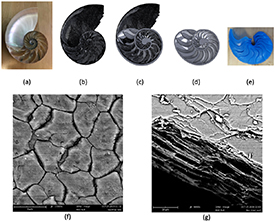
Figure 1. A method for modeling a nautilus-inspired pressure vessel from a Nautilus pompilius shell (a). Image (b) shows the 3D scan of the shell, while figures (c) and (d) show the 3D model made from tracing the 3D scan, displayed both with the scan (c) and without (d). (e) shows silicon casts that were made of the chambers with the purpose of scanning and then performing subtractive modeling. (f) and (g) are SEM results from a sample of the N. pompilius shell to demonstrate the complexity of the material's structure. (f) is a top-down view of the nacre, while (g) is a cross-sectional view showing the layers.
Download figure:
Standard image High-resolution imageThe effects of concave septa, as a theoretical chambered cephalopod morphology, were tested by inverting the inner septal wall concavity. Wall concavity was inverted by retaining the same form of the septa as the concave model, but simply mirroring the concavity and aligning the septa using the 3D-scan and shell measurements as a guide to maintain accurate spacing and chamber volume. The outer wall geometry was identical to the nautilus-inspired model descried above to permit direct comparisons between the two septal wall concavities and their performance under pressure (here termed the 'concave septa' and 'convex septa' models, respectively).
Initial models were printed with Standard Clear resin using the Formlabs Form 2 SLA 3D printer. As a result of the COVID-19 pandemic and material availability, surgical guide (SG) resin (ultimate tensile strength 73 MPa, tensile modulus 2.9 GPA) was utilized heavily in our testing, and was considered an advantage due to its slightly superior material properties over standard clear resin (ultimate tensile strength 65 MPa, tensile modulus 2.8 GPa) [30]. In all of the models tested in this study, we followed Formlabs' curing instructions consistently for each type of resin with the same wash and cure times. Printing the models proved challenging as a result of the extreme thinness of fine features, as well as there was no orientation to print the models without 'cupping', an issue unique to SLA printing of sealed volumes in a liquid resin bath. This generally results in uncured parts within the cup or deformities in the final print. Prints also require supports, which can cause damage when removed from thin surfaces. An optimal print orientation was found to both reduce cupping and result in clean o-ring surfaces to ensure proper sealing of the final assembly. Such an orientation was found by arranging the model to ensure no supports were on any o-ring surfaces by facing the internal side of the shell-half away from the build plate and angling the model at about 45 to the build plate to reduce cupping.
To test the 3D prints the two hemispheres were sealed, placed in weighted bags, and submerged in a hydrostatic pressure chamber. Pressure was applied in each test until implosion. Implosion would result in an audible sound and a sudden drop in the chamber pressure. The maximum pressure achieved before the drop was recorded for each test using a Fluke 700G31 10K PSIG gauge. In order to make a comparison between the complexity of all nautilus-inspired models and the geometries most commonly used for underwater electronics, spherical pressure housings with the same internal volume as the nautiloid models were modeled, printed, and tested with the same wall thicknesses as their nautiloid counterparts. There were concerns that the two halves of the septa in the nautiloid prints were not making proper contact during testing. A 'fused inner wall model' was made and imploded, where the septa halves were manually glued together. Because of the consistency in the result between the fused and not-fused models, it was decided that gluing the halves was unnecessary for future tests and that the septal halves were in fact making proper contact during testing.
FEA simulations were run on each model using Solidworks with the material properties for SG resin, as provided by FormLabs. These properties were limited and did not provide accurate results for a pressure of implosion, but rather provided evidence of points of high stress in the models under hydrostatic pressure that were then compared with the imploded specimens. FEA was performed on both the closed models, which were the same as the models used for practical testing, and on the open-ended models, which more closely resembled the real-nautiloid geometry. These open-ended models provided evidence for the behavior of the outermost septa that the practical testing could not. In order to develop the most consistent and accurate method, the finest mesh size in SolidWorks simulation was used for each of the models and pressure was applied to all outward facing surfaces. Due to the complexity of the CAD models used in these simulations, Solidworks FEA was only able to compile converged values at the finest mesh size, using the blended curvature-based option. In the results presented in figures 2 and 3, the average mesh settings of each individual model was >25 000 nodes and >12 000 elements per simulation. Increasing hydrostatic pressure values were applied to each model with linear static analysis to measure stress, and these forces were applied uniformly against all external faces of the model. As the forces were uniformly applied to the outer walls of the models, there was no rigid body motion and no forces were applied to the internal faces of the model. Like the closed models, the open-ended models had force applied uniformly to all outer walls, not just those of the final septum.

Figure 2. FEA results of increasing hydrostatic pressure on variants of nautilus-inspired pressure vessels where models had concave septa, convex septa, and lacked septa altogether. Panels (a)–(e) show FEA results after applying the corresponding pressure in psi.
Download figure:
Standard image High-resolution image
Figure 3. FEA results of increasing hydrodynamic pressure on the final septa of a nautilus-inspired model. The diagrams in the upper right show the flooded volume on a cross-sectional view of the model and, therefore, illustrate where the hydrostatic force is applied. In addition, these cross-sectional views show the difference between the models with convex and concave septa, respectively. Panels (a)–(e) show the FEA results after applying the corresponding pressure in psi.
Download figure:
Standard image High-resolution imageAs described in previous studies, nacre-like properties are used to evaluate the nautiloid shell performance. Currently, these properties are too complex to accurately model through FEA or to mimic in 3D printing [12, 25]. SEM scans were taken of fragments of the N. pompilius shell to visualize the complexity of the nacre structure (figures 1(f) and (g)). Using the SLA material properties, rather than attempting to mimic nacre, allowed for direct comparisons of idealized designs to be made between the practical testing and the FEA models.
3. Results
As expected, FEA results indicated that the highest stress in all models was on the chamber with the largest internal volume (figure 2(c)). Both the concave- and convex-septa models show similar stress patterns at each pressure, showing no obvious correlation between septal concavity and stress on the outer walls. The points of lowest stress for each chamber appear at the septa, where the outer walls are most supported (figures 2(b) and (c)). Differences in stress can be seen between the two models, where the nautilus-inspired model with concave septa experiences greater stress at the largest chamber, most clearly seen in figure 2(c) with the red region at 300 psi. This is most likely attributed to differences between the chamber volumes due to the freehanded nature and tracing during the modeling rather than indicating any differences between the effectiveness of the septal concavity at buttressing the outer walls. The model without septa showed the highest stress across all five tests, with a more uniform stress pattern than the two models with septa. There is some evidence of high dorsal stress in the 400 psi and the 500 psi results, which is less evident in the two models with septa (figures 2(d) and (e)).
The results of figure 2 are an indication of the effectiveness of septa on buttressing the outer walls, while figure 3 shows the impact of septal concavity on pressure tolerance by exposing and applying pressure to the final septa. The FEA results of the open models show the response of the final septa to hydrostatic pressure (figure 3). As is evident at all five pressure values tested, the nautilus-inspired model with inverted septa experienced higher stress than the nautilus-inspired model.
Because of the inspired and freehanded nature of both models, one-to-one comparisons are difficult to make between the two. The model with concave septa exhibited a mirrored stress pattern at the midline, while the model with convex septa did not, even though both models were perfectly symmetrical (figure 3(d)). The final septa of the model with concave septa shows similar stress patterns similar to those shown in Lemanis et al [12]. For both models, the points of maximum stress were at or near the septal connection to the outer walls. This can be seen most clearly in figure 3(c) at 300 psi for the concave-septa model, with the red sections at the edges of the last septa. These results indicate that septal concavity impacts pressure tolerance and that concave septa experience lower stress in comparison to convex septa.
As shown in figure 4, the nautiloid model was put under hydrostatic loading until failure. For each model that was hydrostatically tested, the point of implosion was at the largest chambers. With increased implosion pressure, the impact of the failure increased. The thinnest-walled model and the model with lowest implosion pressure had the smallest failure, while the 3.5 mm thick print, which imploded at 957 psi, had the largest failure with over half the shell catastrophically broken (figure 4).

Figure 4. Empirical testing results from implosions of nautilus-inspired models with concave septa across increasing outer wall thickness.
Download figure:
Standard image High-resolution imageHydrostatic testing of physical models showed that spheres with the same wall thickness and internal volume outperformed the models with concave septa under pressure (figure 5). As shown by the steeper slope of the spherical models, there is a larger difference in pressure tolerance by increasing the wall thickness of the spherical models than the concave-septa models, but both models showed an increase in pressure tolerance with an increase in outer wall thickness. In a model at 3 mm outer wall thickness, the two halves were fused for each septum to ensure the two model halves were making proper contact. These models resulted in similar results to the model without fused walls which showed that this technique was not necessary for proper septa-half contact. Removing the septa resulted in significantly lower implosion pressure than the models with septa. These experiments serve as a proof of concept for implosion testing coiled cephalopod morphologies and this method has applications beyond the limited number of tests performed on the septa-less and concave-septa models.

Figure 5. Shell implosion under hydrostatic pressure as a function of pressure vessel outer wall thickness. Results for all imploded models are shown, including nautilus-inspired models, nautiloid variants with no septa and fused walls, and spherical models. All models were printed using surgical guide resin, except for the 1 mm thin model, which was printed using clear resin. Trendlines are shown for the spherical and nautilus-inspired results.
Download figure:
Standard image High-resolution image
4. Discussion
In this work, multiple nautilus-inspired pressure housings were successfully modeled, 3D-printed, sealed, and imploded. This method allows for a one-to-one comparison between FEA results and hydrostatic testing of physical models. Material property data of the SLA material was insufficient to fully calculate implosion depth using FEA, but modeling did correctly indicate the failure point of the models with concave septa, at the chamber of the largest volume (figures 2 and 4). Heckman et al highlights the need for hand calculations and using other available data to confirm FEA results, as their study showed that poor FEA practices can lead to misleading conclusions, even if the results look correct [24]. The results of our practical testing indicate that, in the case of pressure testing high-complexity geometries, practical testing can fill the gap where there is no available data or where hand calculations may not be practical.
Each nautilus-inspired model with concave septa imploded at shallower depths than their spherical counterparts of the same outer-wall thickness (figure 5). Both the FEA and hydrostatic testing showed that higher stress was experienced at higher pressures, as shown in the larger failures with the deeper tests in the practical testing (figures 2, 3 and 5). Although the spherical models out-performed these nautilus-inspired models, SLA printing allows for future exploration into the effectiveness of septal-like buttressing for engineered pressure housings.
This method allows for a comparison between the variations of the nautilus-inspired models: one with concave septa, as seen in extant nautilus, and one with convex septa, similar to that of extinct ammonites, which is an important step towards isolating the effects of individual morphological characteristics on performance. This approach should promote future research into different nautiloid morphologies beyond testing pressure tolerance against simple differences in shell thickness, or in septal concavity. For example, additive manufacturing can help to physically model how the striking morphological disparity of the ammonite septal wall, which showed a range of complex, fractal-like patterns [14] physically buttress hydrostatic pressure.
Both the FEA results and the hydrostatic tests of the no-septa models showed that septa reduced stress and increased the pressure tolerance of both the concave- and convex-septa models. Thus, a hypothetical shelled cephalopod without septa would have a shallower native range than the same one with septa (figures 2 and 4). While septal concavity did not significantly impact the stress on the outer walls, when the final septa was exposed to pressure, concave septa were more pressure tolerant than the convex septa (figures 2 and 3). Larger chamber volume resulted in larger stress on the outer walls. This indicates that closer septal spacing would reduce stress on the outer walls by reducing the chamber volume (figure 2). The open-faced models yielded similar stress patterns to those seen in Lemanis et al for the concave-septa model [12]. Points of high stress towards the edges of the outermost septa as well as symmetrical dots of high stress straddling the central axis of the septa were shown in the models (figure 3(e)). The convex-septa model had more uniform septal stress in comparison to the concave-septa model. Both nautilus-inspired models showed a point of low stress at the central axis of the septa (figure 3).
There are many limitations to this method, but it opens a line of questioning into practical testing that has yet to be explored for complex shell morphologies. As mentioned previously and in other studies, mimicking nacre in practical testing or even in material properties in FEA is not possible at this time (figures 1(f) and (g)). This limits the ability to make conclusions about singular species but allows for comparative analysis between species or between morphologies [12]. Adding an o-ring seal shifts the model towards a more nautilus-inspired design and away from biological fidelity. The o-ring seal could be impacting the pressure tolerance and yielding inaccurate results, but our FEA results indicate the side walls of the septa as the primary point of failure even on a model without the seal. The 3D scans created scaffolding for tracing rather than a model ready to print. Because of the freehanded nature of the tracing, our models diverge from biological accuracy and must be considered a biologically-inspired design. Similar work to model and 3D-print nautilus-inspired designs using equation-driven patterned septa has been explored previously [25] and it is worthwhile to compare the performances of these different approaches in the future.
Our results offer new insights into research concerning shelled-cephalopods and could be used to address contrasting findings on if septal complexity impacts pressure tolerance [15, 16]. To do so, septa could be artificially modeled into cylinders such as in Peterman et al [18]. These cylinders could be printed, sealed, and tested to bolster the conclusions developed from FEA. Using 3D scans of fossils, in conjunction with SLA printing and FEA, could be a workflow for determining native depth ranges of extinct species from fossilized specimens [12]. Modeling, printing, and testing of fossilized specimen has already been demonstrated to test evolutionary forcing regarding predation, but not hydrostatic loading [19]. In addition, this method can more generally be used to confirm FEA results, the need for which was illustrated in Heckman et al [24].
5. Conclusion
Applying SLA 3D-printing to create deep-sea pressure housings is a recently developed method in the field of underwater technology. In this study, we applied SLA 3D-printing along with FEA modeling and empirical hydrostatic testing to investigate nautilus-inspired pressure housing designs. Our results validate this approach as a method to compare shell morphologies and may be applicable to determining the habitable depth ranges of extinct shelled cephalopods. By identifying the biomechanical constraints we would provide key context where we know little about the life habits and ecological roles of extinct shelled cephalopods. For the nautilus-inspired models created in this study, the location of the implosion point and the failure of the no-septa model at a lower pressure than either model with septa were substantiated by both the FEA results and hydrostatic testing. As expected, 3D-printed spheres of the same outer wall thickness and similar internal volume outperformed the nautilus-inspired model, while raising the need to further investigate the unique material properties of a nacre/calcium carbonate shell construction. Our presented methods can be used in the future for comparative studies of other chambered-shell morphologies.
Fitting electronics in pressure vessels and fitting pressure vessels into a vehicle design is often like fitting a square peg in a round hole. SLA printing has provided an opportunity to change that. With SLA printing, unique, custom forms that are tailored to specific use-cases, but cannot be easily created through traditional manufacturing processes, can become more common. Nautilus-inspired vessels are just one example of using the full potential of modeling and printing, and this technology can allow future pressure vessels to take on new forms, fitting around the other components in vehicle designs. Septal-like buttressing is another example of vessel structure that has previously been difficult to reliably manufacture, but can now be printed using SLA, potentially providing new vessels with support structures.
Acknowledgments
The authors would like to thank Benedict Gagliardi and the Nature Lab at the Rhode Island School of design for their guidance and use of their 3D scanner and SEM during our research. Thank you to Breanna Motsenbocker and Jason Noel for their help during pressure testing. We would also like to thank the URI Division of Research and Economic Development for supporting this work.
Data availability statement
No new data were created or analyzed in this study.