

Abstract
Today's gecko-inspired robots have shown the ability of omnidirectional climbing on slopes with a low centre of mass. However, such an ability cannot efficiently cope with bumpy terrains or terrains with obstacles. In this study, we developed a gecko-inspired robot (Nyxbot) with an adaptable body height to overcome this limitation. Based on an analysis of the skeletal system and kinematics of real geckos, the adhesive mechanism and leg structure design of the robot were designed to endow it with adhesion and adjustable body height capabilities. Neural control with exteroceptive sensory feedback is utilised to realise body height adaptability while climbing on a slope. The locomotion performance and body adaptability of the robot were tested by conducting slope climbing and obstacle crossing experiments. The gecko robot can climb a 30° slope with spontaneous obstacle crossing (maximum obstacle height of 38% of the body height) and can climb even steeper slopes (up to 60°) without an obstacle or bump. Using 3D force measuring platforms for ground reaction force analysis of geckos and the robot, we show that the motions of the developed robot driven by neural control and the motions of geckos are dynamically comparable. To this end, this study provides a basis for developing climbing robots with adaptive bump/obstacle crossing on slopes towards more agile and versatile gecko-like locomotion.
Export citation and abstract BibTeX RIS
1. Introduction
Geckos possess extraordinary locomotion abilities in various non-structural environments, specifically on slopes and obstacles or bumps, based on their hierarchy adhesion system, along with their unique skeletal system and adaptive movement control of their neural systems. Therefore, geckos are used as bioinspiration for climbing robot development, such as for Stickybots [1–3], Waalbot [4, 5], and UNIclimb [6], which are of great importance for a variety of applications, including disaster rescue, aerospace, and other high-risk tasks. Many climbing robots show reliable abilities in climbing, steering or transition, which largely rely on their adhesive mechanisms [7–11]. Among them, robots exhibiting dry-adhesive mechanisms based on intermolecular forces (inspired by real geckos) can adhere to various smooth surfaces. For example, Waalbot and Waalbot II, which are small agile wheel-legged climbing robots [4, 5], use microfiber footpads and two actuating joints to achieve omnidirectional locomotion on walls and to transition from the ground to the wall. Stickybots [1–3] employed a bio-inspired dry-adhesive material, link-bar mechanism, active foot mechanism, and planned attaching–detaching trajectory to allow for adhesive and stable climbing abilities. Similarly, a climbing robot [12] with a four-bar mechanism can achieve curvature climbing using a specially designed adhesive foot. These gecko-inspired robots have the common features of being light weight and having a low centre of mass, and typically follow the classical control method, which grants gecko-inspired robots appropriate moving abilities while maintaining convenience to engineers.
Whether it is a gecko or a climbing robot, the living and locomotion environment is complex and diverse, including irregularities such as slopes and obstacles or bumps. Although geckos can move quickly in various terrains, even across obstacles, the current robot locomotion ability in such non-structural environments is far behind that of the gecko. This is primarily because the limb structure of the gecko allows for body height adjustments, which provides the necessary body posture to overcome obstacles. Among the existing gecko-inspired climbing robots that have a leg structure with few degrees of freedom (DOFs) and a low fixed body height, Abigaille III [13] is a representative robot designed to overcome problems associated with uneven surfaces on the climbing path. However, an insufficient elevation of the body leads the robot to climb through a ledge (20% of the body height) on one side of the body. Due to inadequate distance sensors, the robot cannot demonstrate body height adaptability when faced with obstacles of different heights. Additionally, real geckos' adaptive movement control allows them to actively adjust their body height when overcoming obstacles, whereas the control method of robots mainly uses a classical engineering control method with no exteroceptive sensory feedback. Furthermore, a planned gait and trajectory are often used for movement in a specific environment with a fixed body height. Consequently, when encountering obstacles, the robot lacks spontaneous adaptability in its moving posture.
To improve the locomotion ability of climbing robots in coping with bumpy terrain or terrain with obstacles, we propose the biomechanical design of a climbing robot with a multi-degrees-of-freedom limb structure and a hybrid soft-rigid adhesive foot. The limb structure is based on the skeletal and kinematic analyses of real geckos
4
. The robot is driven by neural control, based on a central pattern generator (CPG) and a premotor neural radial basis function (RBF) network. The neural control approach can coordinate the limbs, realise gecko-inspired attachment and attachment strategies, generate trot climbing gaits at different speeds, and simultaneously adapt the body posture through exteroceptive sensory feedback to overcome obstacles or bumps. Figure 1 depicts the body height adaption of the robot while passing the obstacle. The height H indicates the robot's body height during its normal climbing mode and the height H' (H'
 H) denotes the robot's body height during adaptation to surpass the obstacle. The inset of figure 1 depicts the 3D ground reaction forces at the left front foot and the right hind foot during the entire process of robot obstacle crossing. During period I, the robot climbed towards the obstacle. During period II, the amplitude reduction of forces in the y and z axes indicates that the robot climbed over the obstacle on which its body rested During period III, the abrupt enlargement of the forces in the y and z axes indicates that the robot body dropped down rapidly.

Figure 1. Gecko-inspired robot with obstacle crossing ability. The ground reaction force while the robot was crossing the obstacle is shown in the left inset, which has three periods, I, II, and III, denoting prior-to-obstacle, over-obstacle, and after obstacle, respectively. The abstract hierarchy of the neural control network, which was applied to the gecko-inspired robot, is shown in the right inset.
Download figure:
Standard image High-resolution imageThe primary contributions of this study are as follows: (i) a gecko-inspired limb design and limb movement strategy for stable climbing on inclined slopes; (ii) a gecko-inspired locomotion strategy with efficient foot attaching and detaching movements; (iii) CPG-based neural control 5 for limb coordination to achieve trot-climbing gaits at different speeds and body height adaptation at different bump heights; (iv) physical robot prototype climbing experiments at different slope angles with different speeds and bump heights, and (v) ground reaction force and dynamic similarity analysis between the robot and gecko.
This paper is divided into five sections. Following the introduction, the biomechanical development of the gecko-inspired robot, including the limb structure and adhesive mechanism, is described in section 2. Section 3 describes the locomotion control based on the gecko foot attachment and detachment strategies, as well as a CPG-based neural control method. Section 4 presents the experiments and results of slope climbing and bump crossing at various slope angles and bump heights, followed by a dynamic similarity analysis of the real gecko and the gecko-inspired robot. Sections 5 and 6 present the discussion and conclusion, respectively.
2. Development of gecko-inspired robot
The skeletal system and strong adhesive system of the gecko allow flexible and stable locomotion in complex environments, such as steep slopes. These systems provide the imitating resources for the physical mechanism of the gecko-inspired robot, such as the limb structure and adhesive mechanism.
2.1. Limb structure
The limb structure of the gecko-inspired robot was developed based on an analysis of the skeletal system and kinematics of real geckos. From the top view of the gecko's bone structure (figure 2(a)), we can see that the limb structure is symmetric on the sagittal plane, and the fore limb and hind limb have a large degree of similarity in structure. Therefore, only the kinematics data of the right front limb were chosen for the analysis and used for all robot limbs (figure 2(a)).
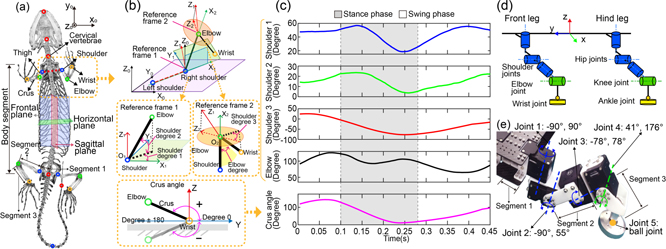
Figure 2. Design of limb structure for the gecko-inspired robot. (a) Skeletal system of a real gecko; different colours represent joints of the real tokay gecko (Gekko gecko) (modified from [14] with permission). (b) The kinematic model of the right front limb of a real gecko. The coloured circles represent the corresponding joints, as shown in (a). The lower figure depicts a side view of the defined crus angle. (c) Kinematics results of a real gecko climbing on a 45° slope. The subplots show the angle movement of the defined joints above, and the grey and white shadows indicate the stance and swing phases, respectively. (d) Sketch of the joint configuration of a gecko-inspired robot based on the real gecko. (e) Motor arrangement and angle ranges of a single leg of the physical gecko-inspired robot.
Download figure:
Standard image High-resolution imageThe gecko limb can be divided into three main parts: the thigh, crus, and footpad. Each part of the limb rotates around different joints. The thigh can be seen as a rotation around the shoulder. The crus can rotate around the elbow joint in a plane built by the thigh and crus. The footpad is linked to the crus by the wrist joint (similar to the shoulder joint), which has three DOFs, but has a shorter linking bar that poses more restrictions on the working space.
The kinematic model for analyzing the joint angle change of the right front limb is shown in figure 2(b). The Y0 axis of the world frame (frame 0) points to the moving forward direction, and the Z0 axis of the world frame points to the perpendicular direction of the gecko moving surface. For better analyzing and decomposing the movement of each joint, the reference frames 1 and 2 were built at the centre of the shoulder joint and elbow joint, respectively. The X1 axis was built along the straight line starting from the left shoulder and pointing to the right shoulder. The Y1 axis was vertical to the plane which was made up of the built X1 axis and the Z0 axis in the world frame. Thus, a Cartesian coordinate (reference frame 1) following the right-hand rule was built in the right shoulder. The shoulder degree 1 (angle between the projected thigh in the X1 OY1 plane and X1 axis) and shoulder degree 2 (angle between the thigh and X1 OY1 plane) were defined under the reference frame 1. The X2 axis was built along the straight line starting from the shoulder and pointing to the elbow. The Z2 axis was created by projecting the Z1 axis onto a plane perpendicular to the X2 axis. The shoulder degree 3 was the rotation angle around its central axis, which was defined as the angle between the projected crus (projected in to the X2 OY2) and the negative Z2. The movement of the elbow joint (green marker) was defined as the angle between the upper and lower arms, indicated by a light yellow shadow in the middle part of figure 2(b). The movement of the wrist was indicated by the angle between the lower arm and the substrate, which is called the crus angle, as shown in the lower part of figure 2(b).
To estimate the moving range of real gecko's limbs, a climbing experiment was conducted with real geckos on a slope of 45°. The results are presented in figure 2(c). The grey shadow or white region indicates that the gecko was in the stance or swing phase of the gait cycle. From the kinematic results, the shoulder degree 1 ranged from approximately 20° to 60°, the shoulder degree 2 ranged from approximately 0° to 25°, and shoulder degree 3 ranged from approximately −80° to 30°, the elbow angle ranged from approximately 65° to 125°, and the variation range of the crus angle in the stance phase was approximately 10° to 130°. Furthermore, the decomposed moving angles above indicate that all these DOFs contribute to the locomotion of the real gecko (figure 2(c)). Based on concepts extracted from the kinematic analysis of real geckos, an abstract structure with four active DOFs for the limb and three passive DOFs for the foot was designed for the gecko-inspired robot.
The design of the leg of the gecko-inspired robot was first formulated according to the analysis of the skeletal system and the developed kinematic model. Figure 2(d) illustrates the joint configuration of the robot, where the shoulder joint of the robot comprises three blue cylinders (three active DOFs), the elbow joint comprises one green cylinder (one active DOF), and the wrist joint is indicated by the orange point (three passive DOFs). Under this concept, the physical right front limb of the robot was constructed (figure 2(e)). Four servomotors provide four active DOFs, and an alloy ball with a ball bearing provides the three passive DOFs. The servomotors 'XM430-W350-R Dynamixel' with a rotational angle of 360° were chosen as the actuators. The selection and arrangement of the driving motors mainly consider that the motion space of the robot is as close as possible to the motion space of the gecko, and define the torque and size requirements of the robot. The shoulder degree 1 (joint 1) ranges from −90° to 90°, the shoulder degree 2 (joint 2) ranges from −90° to 55°, and the shoulder degree 3 (joint 3) ranges from −78° to 78°. The range of elbow joint angle (joint 4) ranges from 41° to 176°, and the motion of the wrist joint (joint 5) ranges from 55° to 125° (figure 2(e)). A summary of the joint angles of the gecko and robot is presented in table 1.
Table 1. Joint angles of the gecko and robot.
| Joints | Gecko | Robot |
|---|---|---|
| Joint 1 | 20°, 60° | −90°, 90° |
| Joint 2 | 0°, 25° | −90°, 55° |
| Joint 3 | −80°, 30° | −78°, 78° |
| Joint 4 | 65°, 125° | 41°, 176° |
After the development of the limb structure, a gecko-inspired robot with a symmetrical body structure was built. The total weight of the robot was 2400 g, and the size of the robot was 35.5 cm × 6 cm × 7.8 cm. A comparison of the standing posture of the gecko and the robot is shown in figures 3(a) and (b), respectively. The blue, green, and orange circles represent the shoulder, elbow, and wrist joints, respectively. A summary table of the sizes of the gecko and robot is shown in table 2.
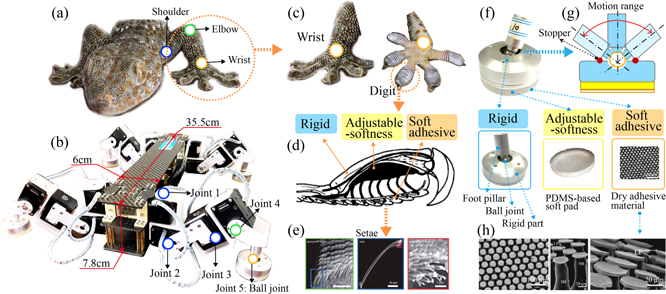
Figure 3. Development of the foot mechanism of the gecko-inspired robot. (a) The sprawling posture of the real tokay gecko (Gekko gecko), the blue, green, and orange colours indicate the shoulder, elbow, and wrist joints, respectively, which are located in the left front limb. (b) Crawling or climbing posture of the designed gecko-inspired robot (Nyxbot). (c) The adhesive foot of the real gecko; the left and right sides of the picture indicate the top and bottom views of the foot, respectively. (d) Functional structure of one digit of the gecko's foot. The arrows indicate regions with different functions, namely rigid parts (arcuate penultimate phalanx), soft adjustable parts (flexor tendon, reticular network, and sinus), and soft-adhesive parts (lamella) (modified from [15] with permission). (e) Nanostructure of setae at different scales {reproduced from [16] with permission [Copyright (2005) National Academy of Sciences]}. (f) and (g) Skeleton and physical picture of the adhesive mechanism for the gecko-inspired robot. The comparable parts of the rigid, adjustable-softness, and soft adhesive parts are shown below. (h) Nanostructure of bio-inspired dry adhesive material at different scales (modified from [19] with permission).
Download figure:
Standard image High-resolution imageTable 2. Size of gecko and robot.
| Body/limb Segments | Gecko | Robot |
|---|---|---|
| Segment 1 | 8 mm | 48 mm |
| Segment 2 | 26 mm | 85 mm |
| Segment 3 | 17 mm | 60 mm |
| Body segment | 95 mm | 355 mm |
2.2. Adhesive mechanism
A good adhesive mechanism on the feet can guarantee that the climbing robot has sufficient adhesive force to move freely and stably on slopes or even walls, as inspired by geckos. The top and bottom views of the foot of the gecko are shown in figure 3(c), and the right part of the figure shows the toes of the gecko, which are the basic adhesion units that generate the adhesive force and interact with the real environment. Based on the anatomy analysis [15] (figure 3(d)) of a single toe, a three-layer structure with different functions was found, as indicated by the arrows. The attachment and detachment movements of the toes are performed by a rigid part referred to as the phalanx. Adaptability and cushioning are provided by the soft adjustable part in the middle, which comprises the flexor tendon, reticular network, and sinus [15]. The adhesive force is generated from the bottom adhesive lamella, which contains an array of setae [16] (figure 3(e)), and the tip bifurcated structure of a single seta shows the origin of the adaptability of the adhesive foot (figure 3(e)).
The three-layer structure of the gecko's foot was extracted as a hybrid soft-rigid adhesive mechanism, which was applied to our gecko-inspired robot. Figures 3(f) and (h) demonstrate the comparable structure of the foot mechanism, comprising three different parts, and the wrist with a ball joint, which share similar functions with those of the gecko foot and wrist. The upper layer of the foot was a rigid layer made of an aluminium alloy. The middle layer is a custom soft layer made of an adjustable PDMS-based soft material [17]. The bottom layer contains a bio-inspired adhesive material. The non-directional adhesive material was chosen as the bottom layer material because of its reliable and promising adhesive ability [18]. The microstructure [19] of the adhesive material used in the robot's foot mechanism is shown in figure 3(h).
To complete attachment–detachment movements, the gecko uses active muscles in its toes to control eversion and adduction. The adhesive foot for the robot was designed as a passive mechanism to reduce the complexity of the gecko-inspired robot. The free ball joint (acting as a wrist) links the lower limb and the cylinder foot. The foot can move freely without considering the directional problem when the foot is attached to or detached from the substrate. The margin of the inner hole of the cylinder foot acts as a stopper (figure 3(g)), which limits the tilting angle of the lower-limb bar and improves the force application when the foot needs to attach and detach from the substrate. Such a hybrid soft-rigid mechanism exhibits appropriate flexibility and more promising features when used on this type of compact design climbing robot with a high payload. The detailed manufacture and performance test can be found in our previous work [17].
3. Locomotion control
Locomotion is related to the survival of an animal, similar to a bio-inspired mobile robot. Moving freely and stably is the most basic requirement for both animals and bio-inspired mobile robots. For geckos, the introduction of an adhesive mechanism requires more accurate muscle control and locomotion strategies. Similar to gecko-inspired robots, locomotion control is also an important research field. Our investigation began with the extraction of the important periods and features of the gecko's movement, and then we applied these principles to the movement of a gecko-inspired robot. Compared with the classical control method, bio-inspired neural control provides a control system which shares greater similarities with the neural control systems of animals. Thus, we introduce a CPG-based neural control network for a gecko-inspired robot. Using this network, we can exploit its neurodynamics in a recurrent network-based CPG and nonlinear transformation in a feedforward RBF-based premotor network to generate basic periodic patterns and shape the patterns to obtain the final proper motor commands. Furthermore, based on the network structure, a machine learning method [20] can be applied to adapt network control parameters to obtain versatile locomotion behaviours. Below, we first describe a gecko-inspired locomotion strategy, followed by the details of the CPG-based control mechanism which encodes the locomotion strategy.
3.1. Locomotion strategy for efficient foot attaching and detaching
Figure 4 demonstrates the locomotion strategy of a real gecko. The stance phase is our focus here because attaching–detaching movements all occurred during this period. An overview of the climbing posture of a real gecko is shown in figure 4(a), where the high-speed camera captured three vivid periods (figure 4(b)) in one step of the gecko's locomotion.
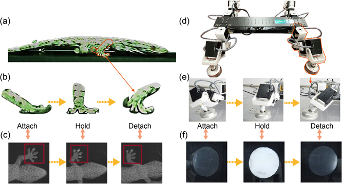
Figure 4. Locomotion strategy of a real tokay gecko and its realisation in our gecko-inspired robot. (a) Locomotion posture of a real gecko; the red line indicates the right front limb of the gecko. (b) Foot attachment and detachment movements of the gecko's right front limb during different periods of the stance phase. (c) Effective adhesive area of the gecko's foot during different periods of the stance phase (bottom view, modified from [22, 23] with permission). Note that the illustration in (a) and (b) and the snapshots in (c) are from different gecko experiments. (d) Locomotion posture of our gecko-inspired robot. The red line indicates the right front limb of the gecko-inspired robot. (e) Foot attachment and detachment movements of the robot's right front limb during different periods of the stance phase. (f) Effective adhesive area of the foot of the robot during different periods of the stance phase (bottom view). A video showing the locomotion strategy of the gecko and robot can be seen at http://manoonpong.com/Nyxbot/Video1.mp4.
Download figure:
Standard image High-resolution imageThe attach, hold, and detach periods are defined according to the specific function of each period, from the start to the end of this step in the stance phase. The lower arm was tilted towards the forward direction from the attachment period to the detachment period. In this manner, the impact force transferred to the main trunk is reduced to better stabilise the locomotion of the gecko.
Attaching and detaching are two crucial periods that can determine the stability and continuity of a gecko's locomotion [21]. The left snapshot in figure 4(b) shows that at the beginning of the attachment period, the toes have an attaching angle with the substrate. Thereafter, the toes are attached to the surface using the rollout action (wherein effective adhesive area increases), while the heel of the foot is set as a fixed point. Detaching occurs at the end of the toes. As the toes gradually roll up, the effective adhesive area decreases. At the end of the detachment period, the entire foot leaves the substrate, and no adhesive force is generated. The vivid change in the effective area is observed from the attachment period until the end of the detachment period, as shown in figure 4(c).
Based on the gecko's locomotion strategy, one step of the gecko-inspired robot in the stance phase (figure 4(d)) is divided into the same three periods. During the hold period (figure 4(e)), the ball joint is in free mode, and the foot can stay at one point, merely rotating the lower arm towards the moving direction to push the body forward. During the attachment and detachment periods (figure 4(e)), the stopper limits the movement of the foot-ball joint, and the bottom adhesive material is controlled to gradually attach and detach from the substrate. Figure 4(f) demonstrates a change in the effective adhesive area of the robot foot comparable to the gecko (figure 4(c)).
A method for generating gecko-inspired leg movements is shown in figure 5(a). There were four steps in total. The first step was to observe the locomotion strategy of a real gecko and extract its leg movements (figure 4). The following three steps are realized below. The specific periods and movements of the robot were planned according to the locomotion strategy, which was extracted from the gecko. The complete period of the gecko-inspired robot in one step is illustrated in figure 5(b). As the timeline progresses, the attach and hold periods first occur, wherein the foot effective adhesive area starts to increase until the entire foot attaches to the climbing surface. Subsequently, one side leg waits for the other side leg to complete the detaching movement in the still stage of the hold period. After sufficient adhesive force is generated, the diagonal legs begin to push backward, thereby moving the body forward. The last two periods also start from the still stage of the hold period, in which the other side foot generates sufficient adhesive force. Thereafter, the foot detaches from the surface and swings to the start of the next moving step.
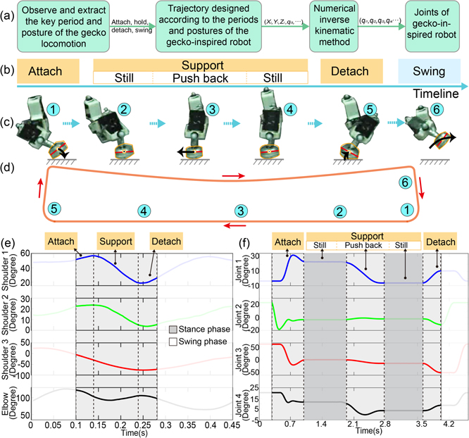
Figure 5. Locomotion strategy of the gecko-inspired robot. (a) Method for generating gecko-inspired leg movements. (b) Period of locomotion in one moving step of the robot. (c) Corresponding moving postures of (b) and snapshots of the foot movement of the right front limb of the gecko-inspired robot. (d) The complete foot trajectory of the right front limb of the gecko-inspired robot. (e) Decomposed joint position change of the right front limb of a real gecko in the stance phase; the dotted lines represent the regions belonging to the different periods that are defined in figure 4(b), and the grey and white shadows indicate the stance and swing phases, respectively. (f) Joint position change of the right front limb of the robot in one step; the dotted lines represent the regions belonging to the different periods that are expressed in (b) and (c), and the grey and white shadows indicate the stance and swing phases, respectively.
Download figure:
Standard image High-resolution imageThe planned moving sequence of the gecko-inspired robot in one step, as observed from the gecko (figures 2(c) and 4(b)), is illustrated in figure 5(c), wherein the curved arrows indicate the tendencies of the foot movement, and the black bar under the foot indicates the ground. Using the moving sequence defined above, the robot can realise continuous adhesive locomotion. Figure 5(d) depicts the hand-crafted moving trajectory of the robot foot and the corresponding moving sequence (figure 5(c)). The red arrows indicate the foot's movement direction. Subsequently, in the third step, the planned trajectory was mapped to the joint space of the limbs using the numerical kinematic method [24]. The mapping between the foot wrist position in a three-dimensional Cartesian space ![$(\boldsymbol{T}={[{P}_{x},{P}_{y},{P}_{z}]}^{\mathrm{T}})$](https://content.cld.iop.org/journals/1748-3190/17/3/036008/revision2/bbac5a3cieqn2.gif) and the joint angle space
and the joint angle space ![$(\boldsymbol{q}={[{\theta }_{1},{\theta }_{2},{\theta }_{3},{\theta }_{4}]}^{\mathrm{T}})$](https://content.cld.iop.org/journals/1748-3190/17/3/036008/revision2/bbac5a3cieqn3.gif) was done by equation (1). The error
e
between the desired foot tip position
T
d
and generated foot tip position
T
c
was used as a cost function (equation (2)).
was done by equation (1). The error
e
between the desired foot tip position
T
d
and generated foot tip position
T
c
was used as a cost function (equation (2)).


e was optimized by using equations (3) and (4). The Jacobian matrix J can be calculated from the Denavit–Hartenberg (DH) parameters of the robot's limb (table A1 and figure A1). The positive scalar α was used as an update rate of the joint positions. It was set to 0.01. We assumed that the optimal wrist position can be obtained after e was smaller than 0.001, i.e. q d ≅ q c .

Figure 5(f) presents the output of the four joints of a single leg. The same joint movements were also applied to the other legs. By comparing the joint position change of the real gecko and the robot (figures 5(e) and (f)), the consistent tendency (increase or decrease) can be found in attach, hold, and detach periods. This demonstrates that the key movements in adhesive locomotion of the real gecko, such as attachment and detachment, have been successfully extracted for the robot. It is important to note that due to our simplified fixed body of the gecko-inspired robot, the still stages in the hold phase were additionally introduced (figure 5(f)) for stability enhancement. Specifically, adding the still stages can ensure firmly surface adhesion before pushing back and obtain a double stance phase before detaching.
3.2. Body height adaptation for obstacle overcoming
The gecko's locomotion strategy, which includes efficient foot attachment and detachment, allows it to stably climb on various slope angles. Its leg structure with many DOFs provides it with additional body height adaptability. Gecko obstacle crossing experiments were carried out to preliminary investigate the body height adaptability when encountering a bump or an obstacle. A gecko was used for the experiments at different slope angles of 0°, 30°, 60°, and 90°, where an obstacle with different heights (10 mm and 20 mm) was placed on the slope. Figure 6(a) exemplifies the gecko's entire obstacle crossing process where the height of the obstacle was set to 20 mm on a slope of 60°. The whole process can be divided into the following periods. In period I, the gecko moved towards the obstacle with its normal body height (low centre of mass). In period II, it began to lift the body up when it detected or its front limb approached the obstacle. In periods III and IV, it maintained its relatively high body height. In period V, its body height began to drop immediately when the front limb crossed over the obstacle while the remaining body part just glided on the obstacle. In period VI, the entire crossing process was completed when the hind limb also crossed over the obstacle. Figure 6(b) shows the corresponding body height adaptation of the gecko during the whole obstacle crossing process. Figure 6(c) depicts all results from the experiments as a percentage of body height elevation at various slope angles and obstacle heights. There is a significant correlation between obstacle height and body height, indicating that the gecko increased its body height when the obstacle height was increased. It raised its body by approximately 35% and 75% on average to overcome an obstacle with heights of 10 mm and 20 mm, respectively. However, there is no clear correlation between slope inclination and body height elevation, i.e. the gecko lifted its body at a certain level with respect to the obstacle height and maintained nearly the same body height even when the slope angle was increased. According to the experimental results, the gecko adapted its body height just enough to clear the obstacle and gravity appeared to have no significant influence on its body adaption.
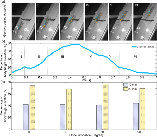
Figure 6. Obstacle crossing experiments of the real gecko. (a) A real gecko climbing and crossing the obstacle (20 mm) on the 60° slope. The blue lines indicate the gecko body, and the yellow lines indicate the gecko limbs. (b) Percentage of the body height elevation (i.e. the ratio of the body height elevation to the default body height) of the corresponding experiment in (a). (c) Comparison of the percentage of the body height elevation when climbing on slopes of 0°, 30°, 60°, and 90° and encountering an obstacle with heights of 10 mm and 20 mm. A video of this experiment can be seen at http://manoonpong.com/Nyxbot/Video2.mp4.
Download figure:
Standard image High-resolution image3.3. CPG-based neural control
To overcome the complex environment with stability and adaptability, geckos require exteroceptive feedback (i.e. vision) and neural systems to detect and then enact locomotion and adaptation strategies. For the gecko-inspired robot, the locomotion strategy described above was encoded using a general neural control framework.
To enable adhesion and obstacle-overcoming abilities in the gecko-inspired robot, CPG-based neural control was used, comprised of four primary layers: sensory input, CPG, premotor neurons, and motor neurons. The sensory layer transmits input signals to adapt the body height of the robot, which enables closed-loop control with exteroceptive feedback for the robot. The signals from the sensory layer are transmitted to the CPG layer, which generates basic periodic patterns that drive the robot joint movements. To satisfy the requirements of efficient foot attachment and detachment behaviour as described above, basic periodic joint movement signals must be shaped to obtain more complex joint patterns. For this purpose, a RBF-based premotor network in the premotor neuron layer was employed to shape or transform the CPG periodic patterns into complex patterns. In this manner, the neural control network can realise the basic joint movements of the robot with efficient foot adhesion. The shaped joint movement signals are finally sent to the motor neuron layer. Different delaylines between the legs were implemented to shift the joint signals between the legs. This was done to achieve a trot gait. The details of each layer are presented below. An overview of the neural network connections is presented in figure 7(a).

Figure 7. Neural control network of the gecko-inspired robot (Nyxbot). (a) Connections and structure of the neural network (CPG combined with RBF). (b) Training process of the RBF network. The insets are one period of rhythmic generation (CPG), RBF kernels, and shaped CPG signal. (c) Training analysis of the RBF network with varying RBF neurons. The top inset depicts the loss (squared error) as a function of the number of RBF neurons and the number of iterations. The middle inset depicts the average loss with respect to different RBF neurons after 1500 iterations. The bottom inset depicts the loss of the network with 80 RBF neurons.
Download figure:
Standard image High-resolution imageThe sensory layer receives infrared (IR) signals from two IR sensors, IR1 and IR2, which are installed on the front and back of the robot, respectively (figure 7(a)). The scaled IR signals, which are mapped into a range from 0 (no obstacle) to 1 (obstacle detected), are transmitted to the sensory preprocessing unit, which uses the below step functions and logistic OR-like gate to control the robot body height.

Here, i1,2 are the sensor signals obtained from the front and back IR sensors. The value of 0.01 is set for the lower threshold, and a value lower than 0.01 indicates that no obstacle is found. The value of 0.5, which is set for the upper threshold, and a value higher than 0.5, indicating that an obstacle is detected (the distance between the sensors and obstacle is approximately 5 cm). The threshold value set was used to prevent the noise generated by the sensors (equation (5)). The sensor signals are converted into three states: state 1 (i1(t) = 1, i2(t) = 0), state 2 (i1(t) = 0, i2(t) = 0), and state 3 (i1(t) = 0, i2(t) = 1). The conversion is expressed by equation (6), which is directly applied to adapt the motor neurons (M12,22 and M14,24) (figure 7(a)) of joint 2 and joint 4 of all legs in the motor layer to adaptively increase or decrease the body height of the robot. A value of 1 lifts the body up, a value of 0 sustains the present body height, and a value of −2 reduces the body height. Here, we set the speed of the body drop to two times (IR = −2) faster than the body lift up (IR = 1). The rationale for this decision is that when a robot encounters an obstacle, the body height must avoid surpassing the obstacle height too much to save energy and to maintain the movement stability. Additionally, when the robot crosses the obstacle, it should return to a normal posture as soon as possible to increase the stability of locomotion.
The CPG layer (figure 7(a)) consists of two discrete-time recurrent neurons (C1 and C2), and the activities of neurons are presented in equation (7) and (8).


The alternate activation and inhibition between the two-neuron centres can provide the robot with basic period signals. The frequency of the outputs can be adjusted by adjusting the weight values of the neurons. Here, the weights are set for w11 = w22 = 1.01 and w21 = −w12 = 0.0182. This weight setup followed the analysis of the CPG neurodynamics described in [25]. Thus, one period (350 time steps) of the CPG output signals can generate adequate central points to control and shape the final joint movement signals for foot attachment and detachment.
The outputs of the CPG are transmitted to the RBF layer, which consists of three sublayers: input (receiving the signals from the CPG layer), kernel (shaping the CPG signals), and outputs (linearly combining the kernel outputs). Neural activation can be acquired using equation (9).

where hi (t) represents the specific kernel in the layer. c1(t) and c2(t) are the output values from the CPG layer. μ1,i and μ2,i are the kernel centres obtained from one period of c1 and c2, respectively. n determines the number of centres, that is, the number of kernels. Here, n = 80, which is set to maintain a sufficient complexity of signals but not too large for computation. The denominator of this equation is s (s = 0.001), which can determine the width of each kernel output. The signals from the kernels were linearly added using simple linear neurons (equation (10)).

wij represents the weights used to scale and combine the transmitted signals between the RBF hidden/kernel and output layers. Here, Oj represents the output signals, which are transmitted to different groups of motor neurons in the motor layer. The motor neurons finally send the motor commands to control the joint angles of the legs as a position control. The gecko-inspired robot has four legs, that is, m = 4. The connections of the premotor neuron layer are also shown in figure 7(a). The final patterns of the neural control network outputs were shaped through wij , which uses the delta-learning rule to train (equation (11)).

The extracted locomotion strategy with foot attaching and detaching movements in a three-dimensional Cartesian space was successfully applied to the robot joint space (see section 3.1 and figure 5). Here, the planned joint positions (Tj (t)) of the gecko-inspired robot were used as the target signals for training the RBF network. α represents the learning rate, which was empirically set to 0.1. Figure 7(b) demonstrates the entire training process for a single joint. Figure 7(c) shows the loss of the training process (calculated from the squared error) with varying RBF neurons. We observed that the minimal network with 80 RBF neurons has the lowest acceptable loss (approximately 0.07). As a result, we used this size for robot control.
The motor layer (figure 7(a)) directly transfers the signals to the physical joints. Equations (12) and (13) describe the detailed parameter settings among the motor layer.


M1,j (t) and M2,j (t) indicate the signals that are transmitted to the real servo motors in the robot. Because we used a trot gait for the robot, the left front and right hind legs used the same motor signals (M1,j (t)). The delayline τ can shift the signals to derive the trot gait. It was set to 175 time steps (half of the CPG signal period). The shifted signals are directly used as commands in the right front and left hind legs. In addition, the sensory layer signals flow into the two depression and extension joints (joint 2 and joint 4) to adapt to the body height while the robot moves to overcome an obstacle. The pseudocode for the implementation of neural control (equations (5)–(13)) is shown in table A2. All parameters in the neural control (described above) together with their values and descriptions, are summarised in table A3.
4. Experimental results
To test the locomotion performance of the robot and compare the similarities of the adhesive force and body height adaptation in the gecko and robot, three robot and one animal experiments were conducted. First, the ground reaction forces were measured using 3D force-testing platforms with an adjustable tilting angle to analyse the dynamic similarities between the real gecko and gecko-inspired robot. Second, the slope climbing ability was tested by conducting climbing experiments on different slopes (0°–60°). Third, obstacle-crossing experiments on different slopes (0°–45°) and obstacles with three different heights (low, medium, high) were used to test the obstacle-overcoming ability of the robot. The overall body height adaptability of both the real gecko and the robot was compared by the final obstacle overcoming experiments.
4.1. Dynamic similarities
To better understand the dynamics of animals and robots, which can contribute to adhesive features, the ground reaction force was measured and analysed. A force-measuring array [26] consisting of 16 independent force sensors, ranging from 0 to 1.5 N with a resolution of 0.1% of full scale (FS), was used to detect the ground reaction force on the three axes of the real gecko. In this experiment, one gecko (Gekko gecko) was used. It climbed 2–3 times for each slope. In total, we used data from five successful runs for each slope in our analysis.
A comparable test of the gecko-inspired robot was conducted on a similar force testing platform [17], but on a larger scale. It consisted of 20 independent 3D force sensors. Each force sensor ranged from −50 N to 50 N on the X- and Y-axes, and −60 to 60 N on the Z-axis. The sensor resolution was 0.1% FS. The comparison groups were set when the gecko and gecko-inspired robot were made to climb on the ground (horizontal plane), 30° slope, and 45° slope. For consistency of the experiments, each robot experiment was conducted five times. The force data of the geckos in the front and hind limbs are shown in figures 8(a, I) and A2(a, I), respectively. The value was computed using the component force along the Y-axis (shear force) divided by the component force along the Z-axis (normal force). A significant increase was observed with the increase in slope angle. This phenomenon is similar to the visualised 3D force profiles displayed in figure 8(b). The force data of the gecko-inspired robot in the front and hind limbs (figures 8(c, I) and A2(b, I)) also show that the proportion of shear force in the resultant force gradually increased, which was consistent with the changing trend of the gecko force data. The visualised 3D force profiles of the robot's front and hind limbs (figure 8(d)) also exhibit the same tendency as the gecko force profiles (figure 8(b)). Furthermore, the gecko and robot's normalized force ranges in the Y–Z plane are analysed and illustrated in figures 8(a, II–IV) and (c, II–IV) for the front limbs, and figures A2(a, II–IV) and (b, II–IV) for the hind limbs. It can be seen that the gecko and the robot had quite similar force ranges for climbing on the ground, ranging from 60° to 120° (around the normal force along the Z-axis). The force ranges shifted towards the shear force along the Y-axis when climbing on the 30° and 45° slopes. In principle, climbing stability can be obtained by increasing the shear force contribution and decreasing the normal force contribution as the slope angle increases [27].
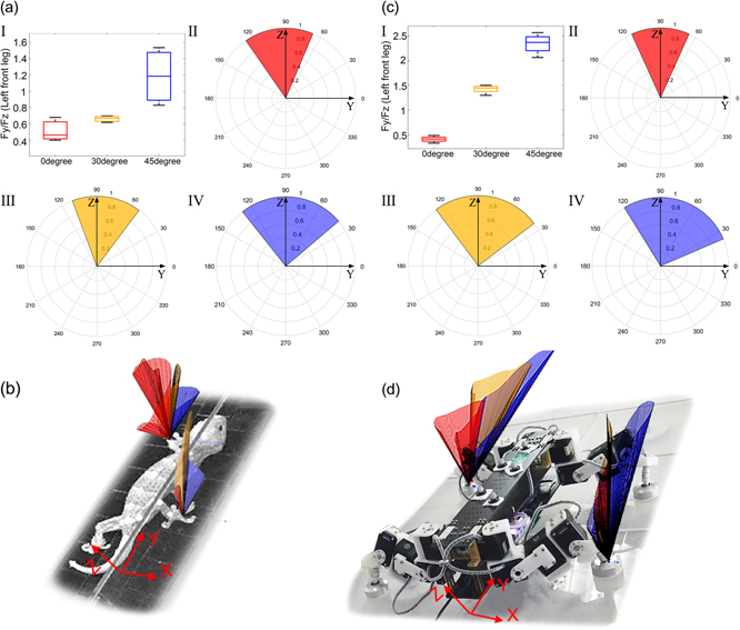
Figure 8. Dynamic similarities of gecko and gecko-inspired robot. (a, I) Ratio of ground reaction force Fy (shear force) and Fz (normal force), which belong to the left front leg of a real gecko (the corresponding colours red, orange, and blue indicate 0°, 30°, and 45° slope angles, respectively). (a, II–IV) Normalized force ranges in the Y–Z plane of the left front leg of a real gecko [II (red), III (orange), and IV (blue) show the data from 0°, 30°, and 45°, respectively]. (b) The real gecko on the force platform with the visualised force profiles. Red, orange, and blue colours indicate the ground reaction force obtained from the slopes of 0°, 30°, and 45°, respectively). (c, I) Ratio of ground reaction force Fy (shear force) and Fz (normal force), which belong to the left front leg of the gecko-inspired robot (the corresponding colours red, orange, and blue indicate 0°, 30°, and 45° slope angles, respectively). (c, II–IV) Normalized force ranges in the Y–Z plane of the left front leg of the robot [II (red), III (orange), and IV (blue) show the data from 0°, 30°, and 45° slope angles, respectively]. (d) The robot on the force platform with visualised force profiles. Red, orange, and blue colours indicate the ground reaction force obtained from the slopes of 0°, 30°, and 45°, respectively.
Download figure:
Standard image High-resolution image4.2. Slope climbing ability
A performance test of the gecko-inspired robot was necessary to validate the robot in terms of its structure and control. The fundamental climbing abilities with surface adhesion were tested using a series of slope-climbing experiments (figures 9(a) and (c)).
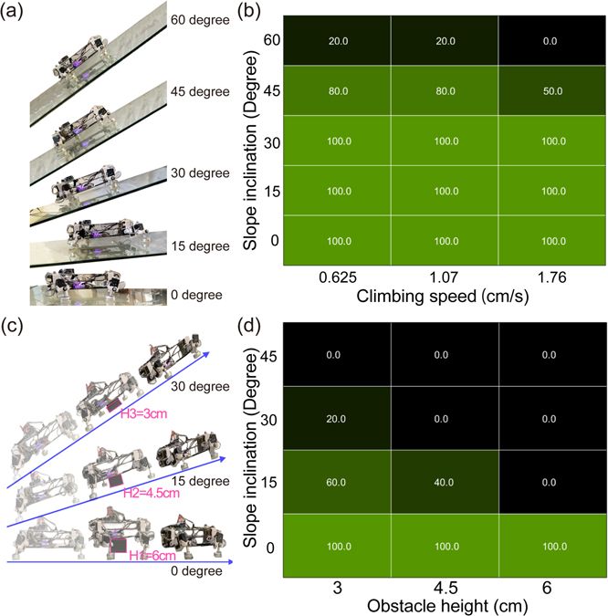
Figure 9. Performance validation experiments of the gecko-inspired robot. (a) Slope climbing experiments: The gecko-inspired robot was tested on slopes of 0°, 15°, 30°, 45°, and 60° at low (0.625 cm s−1), medium (1.07 cm s−1), and high (1.76 cm s−1) speeds. (b) Success rate of the robot while climbing on different slope angles at different speeds. (c) Obstacle crossing experiments. The gecko-inspired robot was tested on the 0°, 15°, 30°, and 45° slopes with an obstacle height of low (3 cm, approx. 38% of body height), medium (4.5 cm, approx. 58% of body height), and high (6 cm, approx. 77% of body height) and a speed of 1.07 cm s−1. (d) Success rate of the robot while crossing obstacles of different heights on slopes with different slope angles.
Download figure:
Standard image High-resolution imageThe robot was able to climb a maximum slope angle of approximately 60° with a success rate of 20%, as shown in figure 9(b). The success rates of the robot when it climbed at different speeds and slope-tilting angles are shown in figure 9(b). A complete climbing distance of at least 80 cm on the platform, without dropping or slipping conditions, was counted as one successful trial. The success rate was computed as the ratio of successful trials to the total number of trials (five trials in total) for one specific experiment. The results show that the gecko-inspired robot exhibited a fast climbing motion (1.76 cm s−1) on a 30° slope; however, the success rate decreased when the slope angle became steeper. The robot can stably climb at a medium speed (1.07 cm s−1) on the 45° slope. In addition, at a low speed (0.625 cm s−1), the robot can climb the maximum slope angle (60°) with a success rate of 20%. A video of this experiment can be seen at http://manoonpong.com/Nyxbot/ Video3.mp4.
4.3. Obstacle-overcoming ability
The obstacle-overcoming ability of the gecko-inspired robot is shown in figure 9(d). The success rate of obstacle crossing decreased dramatically as the slope tilting angle increased. The gecko-inspired robot can cross over an obstacle with a height of 6 cm (approximately 77% of body height) on the ground. The maximum slope angle for the gecko-inspired robot to overcome the obstacle was approximately 30°, with an obstacle height of 3 cm (approximately 38% of body height) (figure 9(c)). Figure 9(a) displays snapshots of the gecko-inspired robot climbing on slope angles of 0°, 15°, 30°, 45°, and 60°. The snapshots of the gecko-inspired robot crossing over different heights of obstacles at slopes of 0°, 15°, 30°, and 45° are shown in figure 9(c). A video of this experiment can be seen at http://manoonpong.com/Nyxbot/Video4.mp4.
The autonomous obstacle-crossing experiment with exteroceptive sensory feedback was performed to demonstrate the adaptability of the body height of the gecko-inspired robot, following the gecko obstacle-overcoming strategy (figure 6). Figure 10(a) shows the entire process of autonomous robot obstacle crossing. The colour bar marks the limb state of the gecko-inspired robot, and the different moving postures of the robot are shown in these snapshots. The robot climbed on a slope with a tilting angle of 15°. When it approached an obstacle with a height of 3 cm, the IR sensor (IR1), installed on the front of the robot, detected the obstacle and sent a signal to the neural control network. Immediately, the robot began to elevate itself (I, II, and III periods) until no obstacles were detected by the front IR sensor. The robot then crossed over the obstacle by sustaining its body height (IV and V periods). When the hind leg moved away from the obstacle, the entire crossing process was completed, and the hind IR sensor (IR2), installed on the back of the robot, detected the obstacle. Thereafter, the robot dropped to its normal height (VI period). Body height adaptation of the robot during the whole crossing process is shown in figure 10(b). The signals from IR sensors are shown in figure 10(c). The pitch-angle signal of the inertial measurement unit (IMU) installed on the robot body shows the posture change of the robot, during climbing with the trot gait (figure 10(d)). The undulation of the pitch angle was caused by the undulation of the body of the gecko-inspired robot.

Figure 10. Autonomous obstacle crossing experiment with body height adaptability. (a) Gecko-inspired robot climbing up the slope and crossing the obstacle. The yellow lines indicate the main body, and the green lines indicate the four limbs. (b) Body height adaptation (the ratio of the body height increment to the default body height) during the experiment. (c) IR sensor signals during the experiment. (d) Signal of the IMU. (e) Signals of joint position sensors of joints 2 (for elevation and depression) of the four limbs. (f) Gait diagram of the four feet. A video of this experiment can be seen at http://manoonpong.com/Nyxbot/Video5.mp4.
Download figure:
Standard image High-resolution imageAn increase in the pitch angle implies that the robot encounters an obstacle and has started to lift its body up (III and IV periods). The inverse pitch angle indicates that more than half of the robot's body has already crossed the obstacle, and the remaining body was laid on the obstacle, such that the robot body tilted downward (negative rotational direction) (V periods). The pitch angle dropped to normal when the robot recovered to its normal height (VI periods). The proprioceptive signals obtained from the joint position sensors in the motors of the robot are shown in figure 10(e). The signals indicate the changes in the elevation (i.e. the joint 2 angles shifting downward) and depression (i.e. the joint 2 angles shifting upward) of the robot's body at the corresponding timing. The corresponding footfalls are shown in figure 10(f). The robot used a trot gait throughout the crossing process.
5. Discussion
Here, we propose a systematic method for developing a minimal gecko-inspired climbing robot to realize basic slope climbing and obstacle crossing abilities without the use of a tail. This is to (1) see the robot's limitations without a tail and (2) ensure that even after missing the added tail, the robot can still climb up a particular level of slope and overcome an obstacle. Thus, other features of gecko inspiration were mainly considered, such as limb structure (figure 2), adhesive mechanism (figure 3), and locomotion and body adaptation strategies (figures 4, 5, and 7). While the robot's limb structure allows it to perform efficient foot attachment and detachment from the substrate, as well as change its body height to overcome obstacles, its adhesive mechanism provides sufficient adhesion for slope climbing like geckos. The locomotion and body adaptation strategies were realized by using neural control based on a hierarchical architecture with low and high-level control. The low-level control, consisting of the CPG and premotor neuron layers, can generate stable climbing behaviour on various slopes with gecko-inspired attachment and detachment movements. The high-level control can change the locomotion mode (i.e. adjusting the body height) via exteroceptive sensory feedback to overcome obstacles autonomously.
The CPG module is based on an SO(2)-based neural oscillator [25]. In principle, it can provide various neurodynamics (e.g. periodic patterns with different frequencies and chaotic patterns [28–30] which cannot be achieved by other conventional oscillators (e.g. Matsuoka oscillator [31], Van der Pol oscillator [32], Hopf oscillator [33], or Rayleigh oscillator [34]). While in this study, we exploited periodic patterns for gait generation, we can simply obtain chaotic patterns by setting the CPG weights to W11 = −5.5, W22 = 0.0, W12 = 1.48, W21 = −1.65 and adding additional bias terms (B1 = −5.73, B2 = 0.25). The chaotic patterns prove behaviourally useful for self-untrapping from a hole in the ground which has been shown in previous study [30]. Thus, by using the versatile neural CPG model, we can use its embedded neurodynamics to generate more complex robot locomotion behaviour without using new oscillators. For the RBF network module, it can be extended by online learning methods to adapt the RBF output weights for online joint trajectory adaptation to deal with various (unpredictable) terrains as shown in [35, 36]. Due to our modular structure, the neural CPG model can be replaced by other oscillator or CPG models and the feedforward RBF network can be replaced or combined with a reservoir computing-based recurrent neural network to obtain motor memory for robust locomotion [37]. In comparison to conventional control methods (such as engineering-based control using robot kinematic and dynamic models [3, 4, 13]), the proposed CPG-based control is more flexible in that its module can be easily replaced or new (neural) modules can be added to achieve new functionality. The control can also provide rich neurodynamics that can be exploited for complex locomotion and learning mechanisms can be applied to modify its synaptic weights (synaptic plasticity) for adaptive locomotion. Such adaptability and versatility might be difficult to achieve using conventional control methods.
Typical climbing robots [3, 4, 13, 38] have been developed with oversimplified limb structures with few (1–3) DOFs to reduce their weight. However, the fewer DOFs or the lower the complexity of the limb structure, the less agility and flexibility of the robot's locomotor skills. Some important characteristics of climbing creatures, such as the real gecko, have been overlooked by these robots. For climbing on different slopes or even over an obstacle, a real gecko requires a changeable body posture. As a result, the centre of mass can be shifted to accommodate different climbing modes (figure 6) [39]. There are two general methods for obtaining inspiration from animals for limb design. One method [40] focuses on the kinematics of animals by examining their foot trajectory; the other method [41] analyses the skeletal system and kinematics of the animals at the same time. The first method can lead to the same problem of oversimplification as the robot mentioned above, the second method can endow similar locomotion features of animals to robots in their mechanical parts. Thus, we analysed the skeletal system and kinematics of real geckos (Gekko gecko). We found that four active DOFs in the limb were deeply involved in each single step of climbing and three passive DOFs were needed to accomplish the movements of the feet (figure 2(c)). The limb structure, adopting four active DOFs and three passive DOFs, was attached to the robot body. We evaluated the body height change ability by performing performance validation experiments. The maximum (77%) body elevation range of the total body height gave the climbing robot the ability to change its body posture to a great extent. The high DOFs (7 DOFs per leg) also benefited the adhesive mechanism design. The abstracted hierarchical structure of the real gecko's feet was applied to the design of the adhesive mechanism for the hybrid soft-rigid robot foot. In comparison to previous climbing robots with dry adhesive feet [3, 4, 13, 38, 42, 43], our robot with hybrid soft-rigid adhesive feet has the maximum payload ability, relatively high holding force, and comparatively low detaching force (table 3). This is owing to the hierarchical foot structure with adequate stiffness of soft material as well as the attaching and detaching approach (see [17] for more details). Note that the effective adhesive area in the table was calculated as the ratio of real contact area to total adhesive material area [17].
Table 3. Comparison of different adhesive feet.
| Rebot's name | Single foot area (cm2) | Payload ability (g) | Holding force (N) | Detaching force (N) | Effective adhesive area (%) | Stiffness | Foot peeling mode | Dry adhesive material | ||
|---|---|---|---|---|---|---|---|---|---|---|
| Soft | Soft-rigid | Type | Shape | |||||||
| Abigaille-III | N/A | 105.8 | 4–5 | 4–5 | N/A |

|

| PDMS | Mushroom | |
| Abigaille-II | 3 | 43.3 | 4.5–5 | 4.5–5 | N/A |

|

| PDMS | Mushroom | |
| Waalbot II | 5.3 | 92.5 | 30 | 30 | N/A |

|

| Polyurethane | Mushroom | |
| AnyClimb-II | 1 | 37.8 | 1.7 | 1.7 | N/A |

|

| Polyurethane | Mushroom | |
| CLASH | 2.7 | 2.5 | 1.2 | 1.2 | N/A |

|

| PDMS | Spatula | |
| Stickybot | 2.9 | 500 | 4–6 | 6 | N/A |

|

| Polyurethane | Spatula | |
| A Tailess gecko robot | 54 | 950 | 8–10 | 8–10 | 52% |

|

| PDMS | Mushroom | |

| 12.6 | 1400 | 10–12 | 4 | 78% |

|

| PDMS | Mushroom | |
Thanks to the bio-inspired limb structure and adhesive feet, the observed attachment and detachment movements of the real gecko can be implemented in the locomotion strategies of our robot. One movement step of a real gecko was abstracted into different periods, and then a specific period of attachment and detachment was realised by the planned movements of the gecko-inspired robot movement. Compared to simply push on and pull off movements with no attaching and detaching strategy, the designed attachment and detachment in the robot's foot has been proven to enhance the attachment [movie S5 (https://stacks.iop.org/BB/17/036008/mmedia)] and reduce the detachment force dramatically (figure A3). Similar results have been observed in the digital movement control of real geckos [22, 23]. However, the difference is that the gecko's digital behaviour is separated from its limb movement, whereas the adhesive pad behaviour of our robot is not. Thus, an undesired movement of the robot limb can have an impact on the surface adhesion efficiency. While this may not have a significant impact on performance at low inclination angles, it will slow down the robot's climbing speed and reduce the success rate as the inclination angle increases. Geckos, on the other hand, use digital hyperextension (DH) and digital gripping, which can change forces during the attachment and detachment of the foot, regardless of limb movement [44–46]. As a result of this active adhesive foot system, they can achieve fast, dynamic, and adaptive locomotion, with foot detachment taking only 15 ms [47]. In this case, a gecko-like active adhesive foot system should be further realized and implemented to improve robot stability and locomotion speed for steep slope climbing. The ground reaction force was measured for the gecko-inspired robot and the real gecko. The 3D ground reaction force profiles (figures 8(b) and (d)) were used to compare the dynamic similarity between the robot and the real gecko. According to our previous study [27], the force profiles (figure 8(b)) provide stable contact between the gecko's feet and the climbing surface, preventing slipping. Our robot also exhibited comparable force profiles (figure 8(d)), which can enhance its climbing stability. The ground reaction force analysis shows a comparable dynamic similarity between the gecko and the robot. This implies that, to some extent, the robot with the multi-DOF leg structure can capture the foot-to-surface attachment and detachment strategies of the gecko properly. Through the analysis, we suggest that the 3D visualization of the force profiles can be a good option for evaluating the performance of climbing robots.
Compared to existing climbing robots [3, 4, 13, 38, 42, 43], the obstacle negotiation ability on slopes of our robot is the most distinguished. The proposed gecko-inspired robot (Nyxbot) demonstrated autonomous obstacle-overcoming ability based on its mechanical structure design, sensor feedback, and control system. The multi-DOF leg structure endows Nyxbot with the ability to exhibit a large elevation range (approximately 77% of the robot's body height), which cannot be achieved by other robots. The neural-based control system with exteroceptive feedback allowed the robot to autonomously adapt to obstacles of different heights (38%–77% of the robot's body height), and the foot peeling strategy helped the robot climb on slopes of various tilting angles (maximum 60°). Table 4 presents a comparison among different climbing robots relying on dry adhesion like our robot. The proposed Nyxbot stands out with respect to autonomous climbing while overcoming obstacles, compared to the existing robots.
Table 4. Comparison of different climbing robots.
| (Autonomous) | |||||||||
|---|---|---|---|---|---|---|---|---|---|
| obstacle | |||||||||
| overcoming | |||||||||
| Foot | (max obstacle height | ||||||||
| Robot's | DOFs of | Exteroceptive | Climbing | peeling | with respect to the | ||||
| name | single leg | feedback | mode | strategy | robot body height) | ||||
| Floor | Max slope | Wall | Floor | Slope | |||||
| Abigaille-III | 3 (active) 1(passive) |

| N/A | N/A |

|

| 20% | 20% | |
| Abigaille-II | 3 (active) |

| N/A | N/A |

|

|

|

| |
| Waalbot II | 1 (active) |

| N/A | N/A |

|

|

|

| |
| AnyClimb-II | 1 (active) |

| N/A | N/A |

|

|

|

| |
| CLASH | 1 (active) |

| N/A | 70° |

|

|

|

| |
| Stickybot | 3 (active) 2(passive) |

| N/A | N/A |

|

|

|

| |
| A Tailess gecko robot | 3 (active) 3 (passive) |

| N/A | 70° |

|

|

|

| |

| 4 (active) 3 (passive) |

|

| 60° |

|

| 77% | 58% | |
aThe robot is manually controlled to step on an obstacle in part.
At present, the success rate of the proposed robot for obstacle climbing on a large slope is still low. Thus, further improvement of the robot structure and control is required. To provide sufficient freedom and torque of the robot, the physical robot becomes large (350 mm in length) and heavy (2400 g), which also results in an increased overturning torque when the robot lifts its body height on a large slope. In addition, the height adjustment process of the robot body generates an undesired outward lateral force to the feet. This can result in an unstable adhesion state of the feet. Thus, a spring with a suitable stiffness will be added to each leg to dissipate the undesired force and maintain adhesion. The current wrist setup, which includes a ball joint and a stopper on each foot, can only provide two binary states (very low or very high stiffness). To obtain compliance or adjustable stiffness, we will introduce springs between the footpad and the foot pillar. A bio-inspired tail [48] will be developed and installed on the robot to reduce or even eliminate the overturning torque. The tail will be also used to alter the force distribution on the feet for balance, gain more pressure on the feet while climbing steep slopes, adjust the body posture to climb over different obstacles, and even avoid slipping when the robot experiences any disturbance. We will also implement an active bendable body that can shift the direction of force from the limbs for agile and energy-efficient sloped surface climbing [49]. In our current setup, force feedback was not included in the control system as such the robot cannot adjust its body and limb postures to encounter disturbances and instabilities. To solve this problem, force feedback control methods [50, 51] and compact force sensors [52] will be implemented to realise the adaptive force distribution among the feet and adapt the leg movements online during climbing. In particular, gradient-based shape-adaptive locomotion control (GRAB) with force feedback [53] will be employed to directly shape the CPG dynamics in the CPG layer in order to prolong the robot's stance phase or to change the robot climbing speed when the adhesion force is low. Furthermore, force feedback-based local leg control and forward models [54] will be used to directly modify motor signals in the motor neuron layer in order to adapt individual legs to search for the ground if the expected adhesion force is missing during the stance phase. Because our neural control has a flexible hierarchical structure, it will be later expanded with high-level goal-directed neural control and short-term memory for adaptive and robust navigation with some memory-based guidance [55, 56].
6. Conclusions
To extend the moving abilities of the gecko-inspired robot and to better understand the adhesive features of climbing animals or robots, a real gecko was used as the bio-inspiration resource. Based on the principles extracted from the analysis of the skeletal system, kinematics, and locomotion strategy of the gecko, the robot limb structure was built with four active DOFs and three passive DOFs to facilitate robot climbing motion and body height adaptation. Hybrid soft-rigid adhesive feet were built to realise controllable attachment and detachment movements, and a CPG-based neural control framework was developed to generate robot climbing behaviours and adapt the body height of the robot. From the experimental results, the performance of the complex robot system integrated with the design of the structure, adhesive mechanism, and control framework was tested and evaluated. Specifically, the gecko-inspired robot can climb on slopes and achieve obstacle crossing by adjusting its body height. Similar dynamic features and independent adhesive forces can be found by comparing and analysing the ground reaction force of the gecko and the robot while they climb on slopes at different angles. To this end, the study provides a direction and underlines the importance of bio-inspiration for the development of industrial adhesive climbing robots, particularly in applications with complex slopes.
Acknowledgments
This work was supported by NSFC (Grant No. 51861135306) (AJ, PM) and the National Key R&D Programme of China, Topic 4-NUAA (Grant No. 2020YFB1313504) (PM). The authors are grateful to the editor and anonymous reviewers for their suggestions in improving the quality of the paper. The authors are also grateful to Anthony Patrick Russell, Stanislav Gorb, Wei Wang, and Yi Song for their permission of the reuse of the pictures of their previous work. The authors thank Weijia Zong and Jiwei Yuan for participating in the experiments. We also appreciate Worasuchad Haomachai, and Potiwat Ngamkajornwiwat for their suggestions.
Data availability statement
The data that support the findings of this study are available on gitlab at the link https://bit.ly/3haf8Zu.
Appendix A
See figures A1–A3 and tables A1–A3.
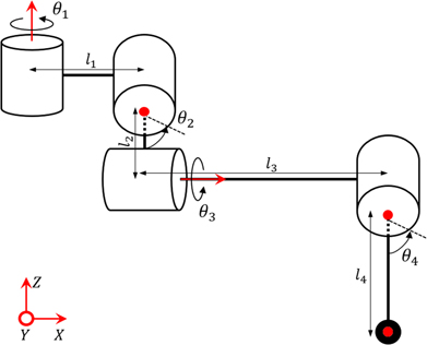
Figure A1. Kinematic diagram of the leg configuration.
Download figure:
Standard image High-resolution image
Figure A2. Dynamic similarities of gecko and gecko-inspired robot. (a, I) Ratio of ground reaction force Fy (shear force) and Fz (normal force), which belong to the right hind leg of a real gecko (the corresponding colours red, orange, and blue indicate 0°, 30°, and 45° slope angles, respectively). (a, II–IV) Normalized force ranges in the Y–Z plane of the right hind leg of a real gecko [II (red), III (orange), and IV (blue) show the data from 0°, 30°, and 45° slope angles, respectively]. (b, I) Ratio of ground reaction force Fy (shear force) and Fz (normal force), which belong to the right hind leg of the gecko-inspired robot (the corresponding colours red, orange, and blue indicate 0°, 30°, and 45° slope angles, respectively). (a, II–IV) Normalized force ranges in the Y–Z plane of the right hind leg of the robot [II (red), III (orange), and IV (blue) show the data from 0°, 30°, and 45° slope angles, respectively].
Download figure:
Standard image High-resolution image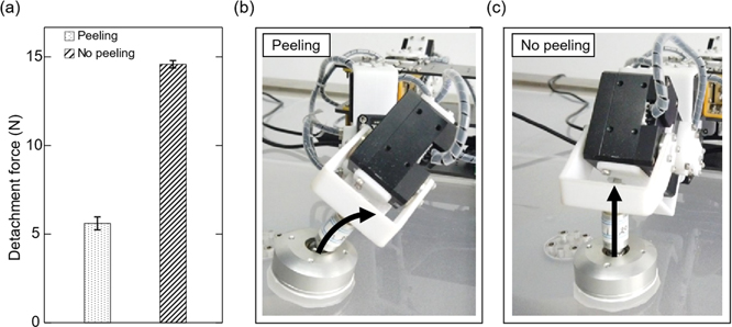
Figure A3. A comparison of detachment force with and without peeling strategy. (a) A resultant detachment force measured on a 3D force platform. (b) The sketch of the detachment with peeling strategy. (c) The sketch of the detachment without peeling strategy. A video of this experiment can be seen at http://manoonpong.com/Nyxbot/Video6.mp4.
Download figure:
Standard image High-resolution image
Table A1. DH parameters for the robot leg (figure A1).
| i | αi | ai | di | θi |
|---|---|---|---|---|
| 1 | π/2 | l1 | 0 | θ1 |
| 2 | −π/2 | l2 | 0 | −π/2 + θ2 |
| 3 | −π/2 | 0 | l3 | π + θ3 |
| 4 | 0 | −l4 | 0 | θ4 |
Table A2. Neural control for locomotion and body height adaptation.
|
Table A3. Neural control parameters.
| Layers | Symbols | Initial values | Description | Variable/constant |
|---|---|---|---|---|
| Sensory layer | i1,2 | 0 | Infrared sensor signals | Variable |
| CPG layer | w |
| Synaptic weights of SO(2) CPG neurons | Constant |
| Premotor neuron layer | μ 1,i |

| One group of center of RBF kernal | Constant |
| μ 2,i |

| Another group of center of RBF kernal | Constant | |
| s | 0.001 | Determine the width of RBF kernal function | Constant | |

|
| Output weights of premotor neuron layer | Variable | |
| Motor neuron layer | τ | 175 | Determine the phase shift between diagonal legs | Constant |
Footnotes
- 4
Note that, in this study, all real gecko experiments were performed as per the Guidelines for Laboratory Animal Management in China. The experimental procedures were approved by the Jiangsu Association for Laboratory Animal Science (Jiangsu, China, approved file No. 2019-152).
- 5
The Python code of the CPG-based control can be accessed from https://bit.ly/3haf8Zu.